Advertisement
Quick Links
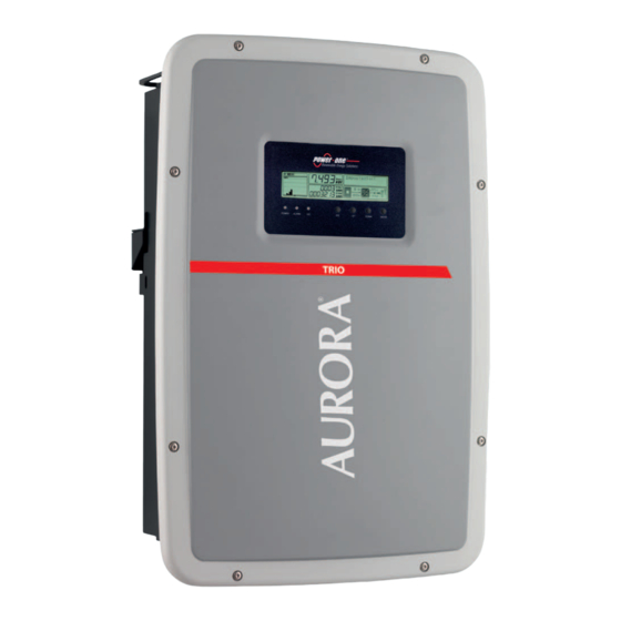
This new generation three-phase inverter for domestic installations, is available in three power ratings: 5.8,
7.5 and 8.5 kW. The compact, transformerless TRIOs are the latest products in the Aurora family for their
performance, ease of use and installation, monitoring and control. The topology of the TRIO 20.0/27.6 inverters
has been redesigned to ensure that the TRIO 5.8/7.5/8.5 models also enjoy high conversion efficiency across
a wide range of input voltages, and the double MPPT gives maximum installation flexibility for an optimal
energy production (TRIO 7.5/8.5 models).
FEATURES
• High speed and precise MPPT algorithm for real time power tracking and improved energy harvesting
• Wide input voltage range
• Two independent MPPT channels for TRIO-7.5/8.5 allows optimal energy harvesting from two sub- arrays
• Flat efficiency curves ensure high efficiency at all output levels ensuring consistent and stable performance
• Datalogger and smart grid functionalities integrated on expansion cards:
• Remote inverter upgrade
• Reactive power management
• Availability of auxiliary DC output voltage (24V, 100mA)
• Natural convection cooling for maximum reliability
• Outdoor enclosure for unrestricted use under any environmental conditions (IP65)
• Sliding cover for the easiest installation and maintenance
• No compulsory maintenance is required
1.
The labels on the inverter have the Agency marking, main technical data and identification of the equipment and manufacturer
®
Made in Italy
DIN V VDE 0126-1-1
AURORA
AURORA
®
PROTECTIVE CLASS: I
MODEL:
PHOTOVOLTAIC INVERTER
PHOTOVOLTAIC INVERTER
TRIO-5.8-TL-OUTD-X-400
V
1000 V
V
1000 V
V
400 V 3Ø, 3W+N+PE
DC max
DC max
AC nom
V
200 - 950 V
V
200 - 950 V
f
50 Hz
DC MPP
DC MPP
nom
V
320 - 800 V
V
320 - 800 V
P
φ
5800 W @ 50 °C amb.
DC, Full Power
DC, Full Power
acr (cos
= 1)
I
2 x 15 A
I
18.9 A
P
φ
5220 W @ 50 °C amb.
DC max
DC max
acr (cos = ± 0.9)
I
2 x 20 A
I
24 A
I
10 A
SC max
SC max
AC max
IP65
IP65
-25 to + 60 °C
-25 to + 60 °C
10 minutes
-13 to +140 °F
-13 to +140 °F
Power-One
Inverter model
01
01
TRIO-XX.X-XX-XXXX-XXX-XXX
Inverter Part Number
02
Inverter Serial Number
03
Week/Year of manufacture
04
If the service password is requested, use the serial number field -SN: SSSSSSSSSS- shown on the identification label
02
03
04
P/N:PPPPPPPPPPP SN:SSSSSSSSSS WK:WW/YY
(affixed to the side)
XXXXXXXXX Q1
In the manual and/or in some cases on the equipment, the danger or hazard zones are indicated with signs, labels, symbols or icons.
Always refer to instruction
General warning - Important
manual
safety information
Protection rating of
IP65
Temperature range
equipment
Always use safety clothing
Positive pole and negative
and/or personal safety devi-
pole of the input voltage (DC)
ces
4.
LEDs and BUTTONS, in various combinations, can be used to view the status or carry out complex actions that are described more fully in the manual.
GREEN On if the inverter is working
POWER
correctly. Flashes when checking the
LED
grid or if there is insufficient sunlight.
YELLOW The inverter has detected an
ALARM
anomaly. The anomaly is shown on the
LED
display.
POWER
ALARM
RED Ground fault on the DC side of
GFI
the PV generator. The error is shown
LED
on the display.
The operating parameters of the equipment are displayed through the display
Description of symbols and display fields.
b1 RS485 data transmission
b13 Daily energy produced
b2 RS485 line present
b14 PV voltage > Vstart
b3 Radio line present.
b15 DC voltage value
b4 Bluetooth line present (*)
b16 DC current value
b5 WiFi line present (*)
b17 DC/DC circuit part
b18 DC/AC circuit part
b6 Warning
b19 AC voltage value
b7 Temperature derating
b8 Instantaneous power
b20 AC current value
b9 MPP scan running
b21 Connection to the grid
b10 Graphic display
b22 Grid status
b11 Power graph
b23 Cyclic view on/off
b12 Total energy
(*) NOT available
5.
Transport and handling
Transport of the equipment, especially by road, must be carried out with by suitable ways and means for protecting the
components (in particular, the electronic components) from violent shocks, humidity, vibration, etc.
Lifting
Where indicated and/or where there is a provision, eyebolts or handles, which can be used as anchorage points, are inserted and/
or can be inserted.
The ropes and means used for lifting must be suitable for bearing the weight of the equipment.
Unpacking and checking
The components of the packaging must be disposed on in accordance with the regulations in force in the country of installation.
When you open the package, check that the equipment is undamaged and make sure all the components are present.
If you find any defects or damage, stop unpacking and consult the carrier, and also promptly inform the Service Power-One.
Equipment weight
Model
Mass weight
Lifting points n°#
TRIO-5.8-TL-OUTD(-S)-400
25 kg
TRIO-7.5-TL-OUTD(-S)-400
28 kg
TRIO-8.5-TL-OUTD(-S)-400
28 kg
6.
Components available for all models
Connector for connecting the configurable
relay
Connector for the connection of the communi-
cation and control signals
L-key, TORX TX25
Two-hole gasket for M25 signal cable glands and
cap
Two-hole gasket for M20 signal cable glands and
cap
Bracket for wall mounting+ Locking screw
TRIO-5.8_7.5_8.5-TL-OUTD-Quick Installation Guide EN RevA
Quick Installation Guide
In addition to what is explained below, the safety and installation information provided in
the installation manual must be read and followed. The technical documentation and the
interface and management software for the product are available at the website http://
www.power-one.com
The device must be used in the manner described in the manual. If this is not the case the
safety devices guaranteed by the inverter might be ineffective.
oriented in different directions (one MPPT channel for TRIO-5.8)
across the entire input voltage and output power range
• PMU expansion card option, with external sensors inputs for monitoring environmental conditions
and additional RS-485 for Modbus protocol
• Ethernet expansion card option with integrated Web Server and remote monitoring capability via
Web Portal (Modbus/TCP supported)
®
®
Made in Italy
Made in Italy
DIN V VDE 0126-1-1
DIN V VDE 0126-1-1
AURORA
®
PROTECTIVE CLASS: I
®
PROTECTIVE CLASS: I
MODEL:
MODEL:
TRIO-7.5-TL-OUTD-X-400
PHOTOVOLTAIC INVERTER
TRIO-8.5-TL-OUTD-X-400
V
400 V 3Ø, 3W+N+PE
V
1000 V
V
400 V 3Ø, 3W+N+PE
AC nom
DC max
AC nom
f
50 Hz
V
200 - 950 V
f
50 Hz
nom
DC MPP
nom
P
φ
7500 W @ 50 °C amb.
V
320 - 800 V
P
φ
8500 W @ 50 °C amb.
acr (cos
= 1)
DC, Full Power
acr (cos
= 1)
P
φ
6750 W @ 50 °C amb.
I
2 x 15 A
P
φ
7650 W @ 50 °C amb.
acr (cos = ± 0.9)
DC max
acr (cos = ± 0.9)
I
12.5 A
I
2 x 20 A
I
14.5 A
AC max
SC max
AC max
IP65
10 minutes
-25 to + 60 °C
-13 to +140 °F
Hazardous voltage
Without isolation transformer
Point of connection for groun-
ding protection.
It is used to access the main menu, to go
ESC
back to the previous menu or to go back to
the previous digit to be edited.
It is used to scroll up the menu options or to
UP
shift the numerical scale in ascending order.
DC
It is used to scroll down the menu options or
AC
DOWN
to shift the numerical scale in descending or-
der.
GFI
ESC
UP
DOWN
ENTER
It can be used to conrm an action, to access
02
01
03
the submenu for the selected option (indica-
ENTER
ted by the > symbol) or to switch to the next
digit to be edited.
: warnings, alarms, channels, voltages, etc.
01
b2
b4
b6
b8
b1
b3
b5
b7
b9
b11
b13
b12
4
4
4
Quantity
Components available for all models
Bolts and screws for wall mounting
2
Quick Installation Guide
2
®
V
DC,
DC
Power
PHOTOVOLTAIC
V
I
max
DC
V
MPP
Full
INVERTER
®
1000
MODEL:
TRIO-20.0-TL-OUTD-XXX-4
N10606
in Italy
PROTECTIVE
0126-1-1
V VDE
DIN
Made
SC max
-2 5to+
max
I
DC
0°F
-1 3to+14
60°C
440
A
2 x 25
V
- 950
2 x 30
IP65
- 800
V
V
A
200
= 1)
= ±0.9)
φ
AC nom
(cos
P
V
AC nom
400
f
20000
nom
AC nom
P
22000
(cos
φ
I
AC max
45 °C
50 Hz
00
V 3Ø,
3W+N+PE
amb.
W @
I
W @
CLASS:
45 °C
V
PHOTOVOLTAIC
®
INVERTER
®
N10606
amb.
10minutes
33 A
max
Full
V
DC,
DC
MPP
V
I
DC
I
max
DC
SC max
Power
A
- 950
V
V
200
- 800
500
V
2 x 40
A
2 x 32
1000
(cos
AC nom
AC nom
P
V
MODEL:
f
400
nom
P
φ
TRIO-27.6-TL-OUTD-XXX-4
0126-1-1
PROTECTIVE
CLASS:
in Italy
V VDE
DIN
Made
I
00
3W+N+PE
V 3Ø,
Power-One
TRIO-XX.X-XX-XXXX-XXX-
01
XXX
-1 3to+14
-2 5to+60°C
0°F
IP65
AC nom
(cos
=±0.9)
φ
27600
= 1)
30000
AC max
I
W @
45 °C
45 °C
amb.
50 Hz
W @
amb.
45 A
01
02
P/N:PPPPPPPPPPP
02
XXXXXXXXX
SN:SSSSSSSSSS
03
WK:WW/YY
10minutes
03
04
04
Q1
Additional components for 7.5 / 8.5kW models
1
Jumpers for configuration of the parallel
2 + 2
input channels
Additional components for models with disconnect switch (-S)
1 + 1
Female quick fit connectors
1 + 2
Male quick fit connectors
2.
01
02
POWER
DC
DC
ALARM
AC
AC
03
GFI
ESC
UP
DOWN
ENTER
04
05
06
07
08
3.
Environmental checks
• Consult the technical data to check the environmental parameters to be observed
• Installation of the unit in a location exposed to direct sunlight must be avoided as it may cause:
- power limitation phenomena in the inverter (with a resulting decreased energy production by the system)
- premature wear of the electrical/electromechanical components
- premature wear of the mechanical components (gaskets) and of the user interface (display)
• Do not install in small closed rooms where air cannot circulate freely
• To avoid overheating, always make sure the flow of air around the inverter is not blocked
• Do not install in places where gases or flammable substances may be present
• Do not install in rooms where people live or where the prolonged presence of people or animals is expected, because of the
noise (about 50dB(A) at 1 m) that the inverter makes during operation
• Avoid electromagnetic interference that can compromise the correct operation of electronic equipment, with consequent
situations of danger.
Installations above 2000 metres
The labels attached to the
On account of the rarefaction of the air (at high altitudes), particular conditions may occur:
equipment must NOT be re-
• Less efficient cooling and therefore a greater likelihood of the device going into derating because of high internal temperatures
moved, damaged, dirtied,
• Reduction in the dielectric resistance of the air that, in the presence of high operating voltages (DC input), can create electric
hidden,etc...
arcs (discharges) that can reach the point of damaging the inverter
All installations at altitudes of over 2000 metres must be assessed case by case with the Power-One Service
10 minutes
50
cm
Hot surfaces
DC
AC
DC
AC
POWER
ALARM
GFI
ESC
UP
DOWN
ENTER
Direct and alternating cur-
15cm
rents, respectively
50
Time need to discharge stored
cm
energy
7.
6 x
10 mm
Ø
POW
ER
ALAR
DC
DC
M
AC
AC
GFI
ESC
UP
DOW
N
ENTE
R
b17
b23
b10
b19
DC
AC
b15
b18
b21
b14
b16
b20
b22
8.
The front cover can be easily opened by sliding it over the
two rails on both inner sides of the inverter, as described in
the procedure below:
• Unscrew the 8 screws that secure the front cover
• Open the cover by pulling it towards you, then push it
upwards from both sides (steps 2 and 3).
At this stage, avoid misplacing the cover.
POW
ER
DC
DC
ALAR
M
AC
AC
GFI
ESC
UP
DOW
N
ENTE
R
• Secure the cover open by pushing it forwards and then
downwards (steps 4 and 5)
9.
Load protection breaker (AC disconnect switch) and line cable sizing
To protect the AC connection line of the inverter, we recommend installing a device for protection against over current and leakage with the following characteristics:
Magnetic protection characteristic
Quantity
Type of differential protection
4 + 4
Power-One Italy S.p.A. declares that the Power-One AURORA transformerless inverters, in terms of their construction, do not inject continuous ground fault currents and the-
refore there is no requirement that the differential protection installed downstream of the inverter be type B in accordance with IEC 60755 / A 2.
Characteristics and sizing of the line cable
1
For the connection of the inverter to the grid, you can choose between a star connection (3 phases + neutral) and a delta connection (3 phases).
The cross-section of the AC line conductor must be sized in order to prevent unwanted disconnections of the inverter from the grid due to high impedance of the line that
Quantity
connects the inverter to the power supply point
Cross-section of the line conductor (mm
1 + 1
Quantity
2 (5.8 kW)
The values are calculated in nominal power conditions, taking into account:
4 (7.5 / 8.5 kW)
1. a power loss of not more than 1% along the line. 2. copper cable, with EPR/XLPE insulation, laid in free air
2 (5.8 kW)
®
®
max
max
V
DC
V
MPP
Full
DC,
Power
I
PHOTOVOLTAIC
DC
DC
PHOTOVOLTAIC
I
I
max
DC
V
DC
V
Full
DC
MPP
V
V
Power
DC,
200
INVERTER
MODEL:
TRIO-20.0-TL-OUTD-XXX-4
INVERTER
- 950
V
1000
V
®
MODEL:
1000
®
200
TRIO-20.0-TL-OUTD-XXX-4
PROTECTIVE
N10606
PROTECTIVE
DIN
DIN
N10606
in Italy
Made
0126-1-1
V VDE
in Italy
Made
CLASS:
V VDE
0126-1-1
-2 5to+
I
max
IP65
0°F
60°C
-1 3to+14
IP65
SC max
-1 3to+14
SC max
0°F
60°C
-2 5to+
A
2 x 25
A
440
- 950
V
- 800
2 x 30
2 x 30
A
V
A
440
- 800
V
2 x 25
V
V
AC nom
22000
W @
= 1)
50 Hz
AC nom
AC max
φ
I
P
V
P
AC nom
(cos
AC nom
φ
= ±0.9)
= 1)
V 3Ø,
(cos
W @
22000
20000
I
nom
P
V 3Ø,
f
400
φ
= ±0.9)
(cos
20000
AC nom
W @
W @
400
f
φ
AC max
(cos
AC nom
P
nom
amb.
33 A
I
3W+N+PE
amb.
45 °C
00
amb.
50 Hz
I
45 °C
3W+N+PE
CLASS:
45 °C
00
45 °C
V
PHOTOVOLTAIC
DC
DC
V
PHOTOVOLTAIC
max
V
MODEL:
INVERTER
®
INVERTER
®
®
®
N10606
N10606
Power-One
Made
Power-One
amb.
10minutes
33 A
10minutes
Power
Full
MPP
IP65
-2 5to+60°C
max
DC
I
max
-2 5to+60°C
I
SC max
V
-1 3to+14
I
DC
max
DC
MPP
DC
V
V
DC,
DC,
SC max
Power
I
Full
- 800
500
V
A
1000
200
TRIO-27.6-TL-OUTD-XXX-4
2 x 40
V
MODEL:
V
- 950
1000
V
V
TRIO-27.6-TL-OUTD-XXX-4
200
2 x 40
- 950
- 800
V
A
A
2 x 32
A
2 x 32
500
V 3Ø,
400
φ
f
AC nom
V
AC nom
P
nom
400
V 3Ø,
(cos
50 Hz
nom
AC nom
P
φ
(cos
30000
= 1)
I
DIN
PROTECTIVE
P
f
φ
= 1)
AC nom
PROTECTIVE
DIN
AC nom
V
P
AC nom
(cos
in Italy
in Italy
00
I
TRIO-XX.X-XX-XXXX-XXX-
3W+N+PE
0126-1-1
0126-1-1
V VDE
CLASS:
P/N:PPPPPPPPPPP
I
V VDE
50 Hz
CLASS:
Made
00
3W+N+PE
TRIO-XX.X-XX-XXXX-XXX-
01
XXX
XXX
01
-1 3to+14
IP65
0°F
0°F
=±0.9)
φ
27600
W @
30000
AC max
W @
AC max
I
W @
27600
W @
(cos
=±0.9)
amb.
45 °C
P/N:PPPPPPPPPPP
amb.
02
45 °C
01
45 °C
45 A
amb.
45 A
45 °C
amb.
02
10minutes
01
02
02
XXXXXXXXX
XXXXXXXXX
03
SN:SSSSSSSSSS
SN:SSSSSSSSSS
03
WK:WW/YY
04
WK:WW/YY
04
4 (7.5 / 8.5 kW)
03
04
03
04
10minutes
Q1
Q1
The models of inverter to which this guide refers are available in 3 power ratings:
e 8.5 kW.
18
16
15
For inverters of equal output power the variant between the various models is the presence or
lack thereof, of the DC disconnect switch
TRIO-5.8-TL-OUTD-400
• Number of input channels: 1
09
• DC disconnect switch
17
10
• Input connectors: screw terminal block
08
16
15
TRIO-7.5-TL-OUTD-400
I ON
TRIO-8.5-TL-OUTD-400
• Number of input channels: 1
• DC disconnect switch
17
19
• Input connectors: screw terminal block
18
16
15
Main components
Display
01
11
LED panel
02
12
Keypad
03
17
13
Front cover
04
08
16
15
14
AC output board
05
Communication and control board
06
Scheda di ingresso DC
07
DC disconnect switch
08
bracket mounting slot
09
17
19
20
Inverter
10
Installation position
• Install on a wall or strong structure suitable for bearing the weight
DC
AC
AC
DC
AC
DC
AC
DC
DC
DC
AC
AC
POWER
ALARM
GFI
ESC
UP
DOWN
ENTER
POWER
ALARM
GFI
ESC
UP
DOWN
ENTER
POWER
ALARM
GFI
ESC
UP
DOWN
ENTER
• Install in safe, easy to reach places
• If possible, install at eye-level so that the display and status LEDs can be seen easily
• Install at a height that considers the heaviness of the equipment
• Install vertically with a maximum inclination of +/- 5°
DC
DC
DC
DC
• To carry out maintenance of the hardware and software of the equipment, remove the covers
ALARM
GFI
ESC
UP
DOWN
AC
AC
ENTER
ALARM
GFI
ESC
UP
DOWN
ENTER
AC
AC
POWER
POWER
on the front. Check that there are the correct safety distances for the installation that will allow
the normal control and maintenance operations to be carried out
DC
AC
DC
AC
DC
AC
DC
AC
POWER
ALARM
GFI
ESC
UP
DOWN
ENTER
POWER
ALARM
GFI
ESC
UP
DOWN
ENTER
• Comply with the indicated minimum distances
• For a multiple installation, position the inverters side by side
• If the space available does not allow this arrangement, position the inverters in a staggered
arrangement as shown in the figure so that heat dissipation is not affected by other inverters
DC
DC
AC
AC
AC
DC
AC
DC
POWER
ALARM
GFI
ESC
UP
ENTER
DOWN
POWER
ALARM
GFI
UP
ESC
DOWN
ENTER
15cm
Final installation of the inverter must not compromise access to any disconnection devices
that may be located externally.
Please refer to the warranty terms and conditions available on the www.power-one.com
website and evaluate any possible exclusion due to improper installation.
DC
DC
AC
AC
AC
DC
AC
DC
POWER
ALARM
GFI
ESC
UP
ENTER
DOWN
POWER
ALARM
GFI
UP
ESC
DOWN
ENTER
A
A
A
1
(step 1)
04
TRIO-5.8-TL-OUTD
Type
Automatic circuit breaker with differential thermal magnetic protection
Voltage/Current rating
Number of poles
Differential sensitivity
2
)
Maximum length of the line conductor (m)
TRIO-5.8-TL-OUTD
TRIO-7.5-TL-OUTD
4
55m
6
80m
10
135m
5.8 kW, 7.5 kW
.
08
TRIO-5.8-TL-OUTD-S-400
• Number of input channels: 1
: No
DC disconnect switch
: Yes
08
08
Input connectors: quick fit connectors (2 pai-
rs)
TRIO-7.5-TL-OUTD-S-400
TRIO-8.5-TL-OUTD-S-400
• Number of input channels: 1
:
No
DC disconnect switch
: Yes
08
08
Input connectors: quick fit connectors (2 pai-
rs)((2 pairs per channel)
Handles
11
Heat sink
12
Bracket
13
Locking screw
14
AC cable gland
15
Service cable glands
16
Anticondensation valve
17
DC cable glands
18
Input connectors (MPPT1)
19
Input connectors (MPPT2)
20
department..
DC
DC
DC
DC
DC
DC
AC
AC
AC
AC
AC
AC
POWER
ALARM
GFI
ESC
UP
DOWN
ENTER
POWER
ALARM
GFI
ESC
UP
DOWN
ENTER
POWER
GFI
ALARM
ESC
UP
DOWN
ENTER
DC
DC
AC
DC
AC
AC
DC
AC
POWER
ALARM
GFI
UP
ESC
DOWN
ENTER
POWER
ALARM
ESC
GFI
UP
DOWN
ENTER
DC
DC
DC
DC
UP
AC
AC
DOWN
ENTER
UP
DOWN
AC
AC
ENTER
POWER
ALARM
GFI
ESC
POWER
ALARM
GFI
ESC
50
cm
DC
DC
AC
AC
DC
DC
AC
AC
DC
DC
AC
AC
ESC
UP
DOWN
ENTER
POWER
ALARM
GFI
ESC
UP
DOWN
ENTER
POWER
ALARM
GFI
ESC
UP
DOWN
ENTER
15cm
POWER
ALARM
GFI
15cm
50
DC
DC
DC
DC
GFI
ESC
UP
ENTER
AC
DOWN
AC
GFI
ESC
UP
DOWN
AC
ENTER
AC
cm
POWER
ALARM
POWER
ALARM
Wall mounting
During installation do not place the inverter
with the front cover
10
facing towards the ground.
04
1
• Position the bracket
perfectly level on the wall and use it as a drilling
13
template.
• Drill the 4 holes required using a drill with 10mm bit. The holes must be
about 70mm deep.
• Fix the bracket to the wall with the 4 wall anchors, 10mm in diameter,
2
supplied.
• Attach the inverter by inserting the two tabs on the bracket
2 slots on the inverter (figures A1 and A2).
• Secure the inverter to the bracket by screwing the 2 lock screws
on both sides of the inverter (figure A
).
3
3
• Unscrew the 8 screws and open the front cover
as described in the fol-
04
lowing paragraph to make all necessary connections. The cover is fitted
into fixed rails and cannot be removed.
2
3
4
TRIO-7.5-TL-OUTD
TRIO-8.5-TL-OUTD
400V /16A
B/C
3/4
A/AC
300mA
Max 10mm
TRIO-8.5-TL-OUTD
2
40m
35m
60m
55m
105m
90m
13 ÷ 21 mm
into the
13
14
5
Advertisement

Related Manuals for Power One Aurora Trio


Summary of Contents for Power One Aurora Trio
- Page 1 TRIO-5.8_7.5_8.5-TL-OUTD-Quick Installation Guide EN RevA The models of inverter to which this guide refers are available in 3 power ratings: 5.8 kW, 7.5 kW e 8.5 kW. Quick Installation Guide For inverters of equal output power the variant between the various models is the presence or lack thereof, of the DC disconnect switch POWER ALARM...
- Page 2 The 7.5 and 8.5 kW power inverter versions are equipped with two independent input channels (and therefore with double maximum power point tracker MPPT), which The following table shows the main components and the connections available on the control and communication board..
Need help?
Do you have a question about the Aurora Trio and is the answer not in the manual?
Questions and answers