Sign In
Upload
Manuals
Brands
power-one Manuals
Inverter
AURORA PVI-STRINGCOMB-S
power-one AURORA PVI-STRINGCOMB-S Manuals
Manuals and User Guides for power-one AURORA PVI-STRINGCOMB-S. We have
1
power-one AURORA PVI-STRINGCOMB-S manual available for free PDF download: Installation And Instruction Manual
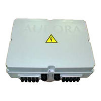
power-one AURORA PVI-STRINGCOMB-S Installation And Instruction Manual (96 pages)
BOXES FOR THE CONNECTION OF STRINGS FOR PHOTOVOLTAIC APPLICATIONS
Brand:
power-one
| Category:
Inverter
| Size: 2 MB
Table of Contents
Table of Contents
3
1 General Instructions on the Use and Reading of this Manual
8
Disposal of Waste
8
Product Labelling
9
Symbols Used in this Manual
9
Figure 1-1: Product Label (Example)
9
Figure 1-2: Power Inputs and Outputs Label
9
Symbols Used on the Pvi-Stringcomb(-S)
11
2 General Information and Features of a Photovoltaic System
12
Photovoltaic Energy
12
Fundamental Elements of a Photovoltaic Field: "Strings" and "Arrays
13
Figure 2-1: Array Composition
13
3 Large Phv Fields and Parallel Strings
15
Why Use Pvi-Stringcomb(-S)
15
Figure 3-1: Effect of a Panel Breakdown with Short-Circuit
16
Figure 3-2: Intervention of Protective Fuse
17
4 Field of Application and General Description of the Parallel String Panel (Psp)
18
Figure 4-1: Pvi-Stringcomb(-S)
18
Figure 4-2: Example of a Photovoltaic System
21
Figure 4-3: Available Inputs/Outputs + Accessories
22
5 Essential Information for Safety
23
Introduction
23
Overview
24
6 Description of the Parts of the Pvi-Stringcomb(-S)
25
Assembly
25
Figure 6-1: Inside of the Pvi-Stringcomb-S
25
Figure 6-2: Inside the Pvi-Stringcomb-S
26
Operation Diagram
27
Figure 6-3: Indicative Electrical Diagram of the Pvi-Stringcomb(-S)
27
Description of the Sections
28
Figure 6-4: Terminal Boards for Positive Strings Input (A) and Negative Strings Input (B) + String Fuse Carrier
28
Input Connections (Ref.§6.1 Items a and B, Figure 6-1)
28
Figure 6-5: Terminal Board for the Connection of the Analogue Inputs
29
Overvoltage Protection - DC Side
29
Signal Inputs and Outputs (Ref.§6.1 Item C, Figure 6-1)
29
DC Isolating Switch (Ref.§6.1 Item G, Figure 6-1)
30
Figure 6-6: DC Isolating Switch (1), Component for Remote Disconnection and
30
Overvoltage Protection - RS485
30
Control Unit and Serial Communication
31
Figure 6-7: Detail of the Micro-Controller and RS485 Serial Zone
31
7 Connection of the Rs485 Line
32
Figure 7-1: Modality for the Passage of the Serial Wire
32
Figure 7-2: Type of Connection for the Pvi-Stringcomb(-S)
33
Connection Methods
34
Figure 7-3: Connection Methods
34
8 Transport and Storage
35
9 Installation
36
Place of Installation
36
Figure 9-1: Example of Box Position
37
Positioning
38
Figure 9-2: Positioning of the Box and an Example of Wire Support
38
Figure 9-3: Complete Use of the PVI-STRINGCOMB(-S) (20 Strings)
39
Electrical Connection
40
Removal of the Guards
40
Figure 9-4: Removal of the Plexiglas Guards
40
Serial Communication
41
Figure 9-5: Rs485 Line Terminal Board
41
Table 9-1: Table of Rs485
41
Figure 9-6: Ground Terminal for Rs485 Line Shielding
42
Figure 9-7: Micro-Switch for RS485 Line Termination
42
Analogue Inputs
43
Figure 9-8 : Terminals for Analogue Inputs Connection
43
Table 9-2: Table of Analogue Inputs Connection
43
PT100 Input
44
Figure 9-9: Terminals for Pt100 Sensor Connection
44
Table 9-3: Table of Pt100
44
Antitheft System Input / Output
45
Figure 9-10: Example of Antitheft System Connection
45
Figure 9-11: Terminals for Antitheft System Alarm Connection
46
Table 9-4: Table of Antitheft System Alarm Connection
46
Digital Inputs
47
Figure 9-12: Terminals for Digital Inputs Connection
47
Remote Disconnection Module
48
Figure 9-13 : Terminals for Remote Disconnection Module Connection
48
Table 9-5: Table of Digital Inputs Connection
48
Table 9-6: Table of Remote Disconnection Module Connection
48
24VDC External Power Supply
49
Figure 9-14: Terminals for External +24Vdc Supply Connection
49
Table 9-7: Table of External
49
Figure 9-15: External +24Vdc Supply Switch
50
Isolating Switch Auxiliary Status Contact
51
Figure 9-16: Isolating Switch Status Connector
51
Table 9-8: Table of Isolating Switch Auxiliary Contact Connection
51
Earth Connection
52
Check on Inverter Side Connections
52
Connection of the Positive Output Wire (+)
52
Figure 9-17: Cable Gland for Ground Connection
52
Connection of the Positive Pole of the Strings (+) [For Max 10 Strings]
53
Figure 9-18: Cable Gland for Positive Strings Connection
53
Figure 9-19: Use the Special Screwdriver on the Terminals
54
Connection of the Negative Poles of the Strings (-) [For Max 10 Strings]
55
Figure 9-20: Cable Gland for Negative Strings Connection
55
Connection of Strings [Over 10 Strings]
56
Setting the DC Switch (Only Version -S)
56
Figure 9-21: Led
56
Connection of the Other PVI-STRINGCOMB(-S)
57
Closing the DC Switch (Only Version -S)
57
Final Checks
57
Closing the Cover
57
Assigning the FIELD NUMBER
57
10 Disconnection and Maintenance
58
Disconnection of the Pvi-Stringcomb(-S)
58
Complete Disconnection
59
Disconnecting the Strings
60
Maintenance (Replacement of Fuses / Dischargers)
61
Replacing the Dischargers
61
Replacing the Fuses
61
11 Before Using the Software
62
Installation of Software
62
12 Monitoring and Configuration Interface
63
Conventions Used
63
Access Levels
63
First Installation
64
Assigning the Field Number
67
What Is the Field Number
67
Figure 12-1: Example of a Complete System Map
68
Operations for Assigning the Field Number
69
Pvi-Stringcomb Manager
71
S.comb Baud-Rate Setting
72
PVI-STRINGCOMB Monitoring (Global)
73
Figure 12-2: Global Monitoring
73
PVI-STRINGCOMB Monitoring (Single)
74
Figure 12-3: Single Monitoring
74
Figure 12-4: Pvi-Stringcomb(-S) S
75
Figure 12-5: Current
76
Detail of Configuration Sub-Menu
78
Configuration Alarm Parameters
78
Configuration String Current Settings
79
Configuration Aux Inputs Settings
82
Figure 12-6: S2 Switch to Enable
83
Configuration Digital Inputs Settings
84
Figure 12-7: Auxiliary Inputs Monitoring
84
Figure 12-8: S4
85
Figure 12-9: Digital Inputs Monitoring
86
Monitoring Examples
87
13 Troubleshooting
90
Table 13-1: Troubleshooting
90
Before Contacting the Technician (Questionnaire)
92
14 Appendixes
93
Appendix A: Technical Data
93
Table 14-1: Technical Data
93
Appendix B: Declaration of Conformity
95
Advertisement
Advertisement
Related Products
power-one AURORA PVI-STRINGCOMB
power-one AURORA PVI-STRINGCOMB-MC
power-one AURORA PVI-STRINGCOMB-S-MC
Power One AURORA
Power One Aurora CCD
Power One AURORA PVI-OUTD-US Series
Power One Aurora Universal Industrial
Power One 10kW-SGTU-103
Power One 12.5kW-SGTU-1253
Power One 15kW-SGTU-153
power-one Categories
Inverter
Battery Charger
Power Supply
Remote Control
Media Converter
More power-one Manuals
Login
Sign In
OR
Sign in with Facebook
Sign in with Google
Upload manual
Upload from disk
Upload from URL