
Subscribe to Our Youtube Channel
Related Manuals for Power One AURORA PVI-7200-WIND-INTERFACE


Summary of Contents for Power One AURORA PVI-7200-WIND-INTERFACE
- Page 1 ® AURORA Wind Box Interface INSTALLATION AND OPERATOR’S MANUAL Model numbers: PVI-7200-WIND-INTERFACE PVI-4000-WIND-INTERFACE PVI-2500-WIND-INTERFACE Rev. 4.0...
- Page 2 REVISION TABLE Document Author Date Change Description Revision 5 Sept 2006 First release of the document 15 June 2006 Additional Model revision 19 Dec 2008 Additional Model revision Paolo Ferrini 16 Apr 2009 Additional Information SAVE THESE INSTRUCTIONS! IMPORTANT SAFETY INSTRUCTIONS PVI-7200-WIND-INTERFACE PVI-4000-WIND-INTERFACE PVI-2500-WIND-INTERFACE (available upon request)
- Page 3 Installation and Operator’s Manual Page 3 of 20 (Aurora Wind Interface Rev 4.0) IMPORTANT SAFETY INSTRUCTIONS This manual contains important safety and operational instructions that must be accurately understood and followed during the installation and maintenance of the equipment. To reduce the risk of electrical shock hazards, and to make sure the equipment is safely installed and commissioned, special safety symbols are used in this manual to highlight potential safety risks and important safety information.
- Page 4 Installation and Operator’s Manual Page 4 of 20 (Aurora Wind Interface Rev 4.0) USEFUL INFORMATION AND SAFETY STANDARD FOREWORD The installation of AURORA must be performed in full compliance with national and local standards and regulations AURORA has no internal user serviceable parts other than fuses. For any maintenance or repair please contact the nearest authorized repair center.
-
Page 5: Table Of Contents
Installation and Operator’s Manual Page 5 of 20 (Aurora Wind Interface Rev 4.0) Contents Wind Box Interface Description - WBI ..........6 WBI Operating Parameters ................7 WBI Block Diagram ..................8 System Block Diagram ................9 Operating Modes of the Wind System:............10 1.4.1 Off Mode....................10 1.4.2... -
Page 6: Wind Box Interface Description - Wbi
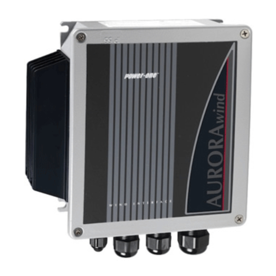
Installation and Operator’s Manual Page 6 of 20 (Aurora Wind Interface Rev 4.0) 1 Wind Box Interface Description - WBI The AURORA Wind Box Interface is an integral part of the wind energy system. The WBI serves four purposes. • To rectify the “Wild AC” from wind turbine generator into DC input for the inverter. -
Page 7: Wbi Operating Parameters
Installation and Operator’s Manual Page 7 of 20 (Aurora Wind Interface Rev 4.0) WBI Operating Parameters Value Description Aurora WBI Input voltage range (no damaging) 0 Vac to 400 Vac Input voltage range (operating) 40 Vac to 400 Vac Input frequency range 0Hz to 600Hz * Max. -
Page 8: Wbi Block Diagram
Installation and Operator’s Manual Page 8 of 20 (Aurora Wind Interface Rev 4.0) 1.2 WBI Block Diagram The AURORA WBI is designed to be used with the Aurora Wind Inverter. Figure 1: Wind Box Interface Block Diagram... -
Page 9: System Block Diagram
Installation and Operator’s Manual Page 9 of 20 (Aurora Wind Interface Rev 4.0) 1.3 System Block Diagram Figure 2: Typical Wind System block diagram The wind turbine must have a primary safety means of limiting the wind turbine speed, this typically is a some type of furling method, blade stalling, self limiting airfoil design, electric safety brake or any other system may exist Power-One supplies the products detailed with pictures in the above block scheme. -
Page 10: Operating Modes Of The Wind System
Installation and Operator’s Manual Page 10 of 20 (Aurora Wind Interface Rev 4.0) 1.4 Operating Modes of the Wind System: Mode WBI Output Diversion Inverter Voltage Load (Vdc) < 50 Vdc Un properly powered Grid Check 50 < Vdc < 530 Operative Grid Check Export... -
Page 11: Wbi Connections
Installation and Operator’s Manual Page 11 of 20 (Aurora Wind Interface Rev 4.0) 2 WBI Connections WARNING: Always safety brake the wind turbine and disconnect the AC grid Circuit Breaker before opening the WBI. 2.1 Required System Connections In the following table are shown input and output pass through openings and glander to be used for the US version (not provided) and provided plastic glander sizes for all other non US versions. - Page 12 Installation and Operator’s Manual Page 12 of 20 (Aurora Wind Interface Rev 4.0) Figure 4: Glanders designations for standard version (non US)
-
Page 13: Wind Speed Feed Back
Installation and Operator’s Manual Page 13 of 20 (Aurora Wind Interface Rev 4.0) 2.2 Wind Speed Feed back The wind speed feed back is an open collector source. The generated pulse train has frequency identical to the generator frequency. Max pull up voltage = 24Vdc; zero level = 1.4Vmax;... -
Page 14: Assembly And Mounting Instructions
Installation and Operator’s Manual Page 14 of 20 (Aurora Wind Interface Rev 4.0) 3.1 Assembly and Mounting Instructions The unit shall be installed in a location so that it is not expected to be casually contacted by person with the external heat sink. 3.1.1 Mounting Height The WBI must be mounted at least 1m (3 feet) above floor level on a vertical surface. -
Page 15: Diversion Load Connection
Installation and Operator’s Manual Page 15 of 20 (Aurora Wind Interface Rev 4.0) 3.3 Diversion Load Connection The value of the Diversion Load resistor is determined by the wind system manufacturer using wind generator characteristics. • Connect the Brake – terminal to the corresponding terminal properly sized diversion load. -
Page 16: Wind Input Power-Up
Installation and Operator’s Manual Page 16 of 20 (Aurora Wind Interface Rev 4.0) 3.6.2 Wind input power-up • Monitor wind speed and at a safe wind speed release the Safety brake on the wind turbine. (Consult wind turbine manufacturer for the safe wind speed release) •... -
Page 17: Trouble-Shooting
Installation and Operator’s Manual Page 17 of 20 (Aurora Wind Interface Rev 4.0) 4 Trouble-shooting Trouble-shooting should only be done by trained and qualified personnel. Trouble- shooting involves hazardous voltages and energies. Symptom Measurement/verify Possible Cause • Exporting initial point Aurora Wind Inverter, Measure WBI Output;... - Page 18 Installation and Operator’s Manual Page 18 of 20 (Aurora Wind Interface Rev 4.0)
- Page 19 Installation and Operator’s Manual Page 19 of 20 (Aurora Wind Interface Rev 4.0)
- Page 20 Installation and Operator’s Manual Page 20 of 20 (Aurora Wind Interface Rev 4.0)
Need help?
Do you have a question about the AURORA PVI-7200-WIND-INTERFACE and is the answer not in the manual?
Questions and answers