
Subscribe to Our Youtube Channel
Related Manuals for MTU 8V2000M40A


Summary of Contents for MTU 8V2000M40A
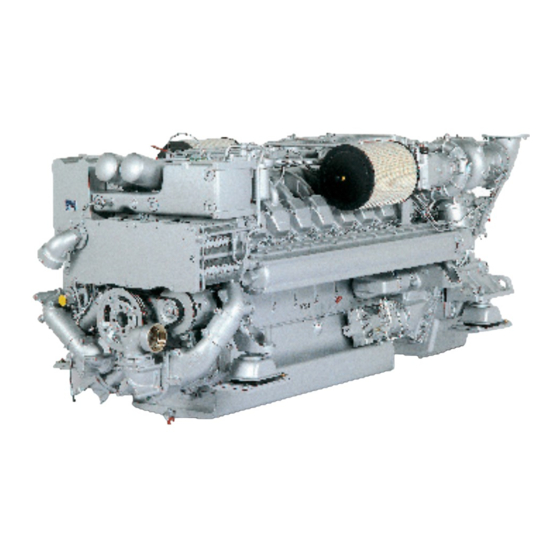
- Page 1 Operating Instructions Diesel engine 8V2000M40A, 8V2000M40B 8V2000M41A, 8V2000M41B 12V2000M40A, 12V2000M40B 12V2000M41A, 12V2000M41B 16V2000M40A, 16V2000M40B 16V2000M41A, 16V2000M41B MS150031/06E...
- Page 2 All information in this publication was the latest information available at the time of going to print. MTU Friedrichshafen GmbH reserves the right to change, delete or supplement the information provided as and when required.
-
Page 3: Table Of Contents
Table of Contents 1 Safety 3.12 12V 2000 M40A engine data: Separate heat exchanger, reference conditions: 45 °C 1.1 Important provisions for all products intake air temperature 1.2 Personnel and organizational requirements 3.13 16V 2000 M40A engine data: engine- 1.3 Transportation mounted heat exchanger, reference 1.4 Safety regulations for maintenance and conditions: 25 °C intake air temperature... - Page 4 6 Troubleshooting 7.11.1 Air filter – Replacement 7.11.2 Air filter – Removal and installation 6.1 ECU alarms 7.12 Air Intake 6.2 Troubleshooting 7.12.1 Service indicator – Signal ring position check 6.3 LOP fault messages 7.13 Starting Equipment 7.13.1 Starter – Condition check 7 Task Description 7.14 Lube Oil System, Lube Oil Circuit 7.1 SOLAS...
- Page 5 8.2 MTU Contact/Service Partners 7.23.1 LOP and connectors – Cleaning 7.23.2 LOP – Visual inspection 7.23.3 LOP – Running test procedures 9 Appendix B 9.1 Special Tools 8 Appendix A 9.2 Index 8.1 Abbreviations MS150031/06E 2016-010 | Table of Contents | 5...
-
Page 6: Safety
The maintenance schedules of the manufacturer must be observed over the entire life cycle of the product. Replacing components with emission labels On all MTU engines fitted with emission labels, these labels must remain on the engine throughout its opera- tional life. -
Page 7: Personnel And Organizational Requirements
1.2 Personnel and organizational requirements Organizational measures of the user/manufacturer This manual must be issued to all personnel involved in operation, maintenance, repair, assembly, installa- tion, or transportation. Keep this manual handy in the vicinity of the product such that it is accessible to operating, maintenance, repair, assembly, installation, and transport personnel at all times. -
Page 8: Transportation
1.3 Transportation Transport without flange-mounted gearbox Illustration is essentially valid for 8V 2000 M engines Illustration is essentially valid for 12/16V 2000 M engines Transport with flange-mounted gearbox Illustration is essentially valid for 8V 2000 M engines 8 | Safety | MS150031/06E 2016-010... - Page 9 The eyebolts mounted at the driving end and on the gearbox must not be used for transporting plants with flange-mounted gearboxes. Only use transport and lifting devices approved by MTU. Take the engine's center of gravity into account. MS150031/06E 2016-010 | Safety | 9...
- Page 10 Only set down engine on a firm, level surface. Make sure that the consistency and load-bearing capacity of the ground or support surface is adequate. Never set an engine down on the oil pan unless expressively authorized to do so by MTU on a case-to-case basis.
-
Page 11: Safety Regulations For Maintenance And Repair Work
1.4 Safety regulations for maintenance and repair work Safety regulations when preparing to perform maintenance and repair work Have maintenance or repair work carried out by qualified and authorized personnel only. Allow the product to cool down to less than 50 °C (risk of explosion for oil vapors, fluids and lubricants, risk of burning). - Page 12 Carry out appropriate cleaning procedures to clean and inspect components requiring special cleanness (e.g. components carrying oil, fuel, or air). Always seal connections with caps or covers if a line is removed or opened. Fit new seals when re-installing lines. Never bend lines and avoid damaging lines, particularly the fuel lines.
- Page 13 Before starting work, pay attention to the following: • Vent the installation/removal device, the pumps and the pipework at the relevant designated points. • For hydraulic installation, screw on the tool with the piston retracted. • For hydraulic removal, screw on the tool with the piston extended. For a hydraulic installation/removal device with central expansion pressure supply, screw spindle into shaft end until correct sealing is established.
- Page 14 Measuring component dimensions Workpieces, components and measuring equipment lie in the specified tolerance range at a reference tem- perature of 20 °C. 14 | Safety | MS150031/06E 2016-010...
-
Page 15: Fire Prevention And Environmental Protection, Fluids And Lubricants, Indirect Materials
Indirect materials, fluids and lubricants may be hazardous or contain toxic substances. Observe the informa- tion provided in the safety data sheet for the product when using indirect materials and other chemical sub- stances. The safety data sheet may be obtained from the relevant manufacturer or from MTU. Used oil Used oil contains harmful combustion residue. - Page 16 Compressed air • Unauthorized use of compressed air, e.g. forcing flammable liquids (hazard class AI, AII and B) out of con- tainers, risks causing an explosion. • Wear goggles when blowing off components or blowing away chips. • Blowing compressed air into thin-walled containers (e.g. containers made of sheet metal, plastic or glass) for drying purposes or to check for leaks risks bursting them.
-
Page 17: Standards For Safety Notices In The Text
1.6 Standards for safety notices in the text DANGER In the event of immediate danger. Consequences: Death, serious or permanent injury! • Remedial action. WARNING In the event of a situation involving potential danger. Consequences: Death, serious or permanent injury! •... -
Page 18: General Information
2 General Information 2.1 Engine side and cylinder designations 1 Left engine side (A-side) 3 Right engine side (B-side) 2 Engine free end in accord- 4 Engine driving end in ac- ance with DIN ISO 1204 cordance with (KGS = Kupplungsgegen- DIN ISO 1204 (KS = Kup- seite) plungsseite) -
Page 19: Product Description
• Data processing logistics for analog and binary signals; • Interface for data transfer to CAN field bus for remote control and ship-side monitoring; • RS 232 interface for connection of MTU dialog unit. MS150031/06E 2016-010 | General Information | 19... - Page 20 • Interface to CAN field bus for connected, communicating monitoring system components. SOLAS – Fire protection specifications All fuel lines with fuel pressure >1.8 bar are fitted with SOLAS-compliant covers as per MTU standard MTN5233. All oil lines with oil pressure >1.8 bar are fitted with SOLAS-compliant covers as per MTU standard MTN5233.
- Page 21 MS150031/06E 2016-010 | General Information | 21...
- Page 22 Lube oil system covers 22 | General Information | MS150031/06E 2016-010...
- Page 23 MS150031/06E 2016-010 | General Information | 23...
- Page 24 Special unions The following types of union are spray-proof in case of leakage even without covers and have been confirmed as being SOLAS-compliant by GL and DNV. Plug-in pipe union Design precludes lateral spray as the point of separation is shielded by the sleeve (4). Only seepage along the pipeline is possible whereby the pressure is greatly reduced by a faulty O-ring (3).
- Page 25 High-pressure unions 1 Jacket pipe 8 Thrust ring 15 Union nut 2 HP line 9 Union nut 16 Thrust ring 3 O-ring 10 Union nut 17 External pipe of HP line 4 Union nut 11 Connecting piece 18 Internal pipe of HP line 5 Recess for O-ring 12 Snap ring 19 Ball-type seal area...
- Page 26 Shielding of fuel filters and lube-oil filters Shielding with plastic ring The plastic ring (1) precludes lateral spray. The fluid is diverted to the catch basin whereby the pressure is greatly reduced. Shielding by overlapping design The overlap (1) precludes lateral spray. The fluid is diverted to the catch basin whereby the pressure is greatly reduced.
-
Page 27: Series 2000 M40A/B - M41A/B
2.3 Series 2000 M40A/B - M41A/B Engine – Overview of functional groups 010 Crankcase and externally 080 Fuel system (low pressure) 180 Lube oil system/lube oil cir- mounted components 100 Exhaust turbocharger cuit 020 Gear train 110 Intercooler 200 Coolant circuit 030 Crank drive 120 Air intake/air supply 230 Mounting/support... -
Page 28: Sensors And Actuators - Overview
2.4 Sensors and actuators – Overview Engine overhead view 1 Intake air temperature 4 Lube oil differential pres- 7 Lube oil temperature 2 Fuel pressure after filter sure 8 Lube oil pressure 3 Fuel temperature 5 Lube oil pressure 6 Coolant level 28 | General Information | MS150031/06E 2016-010... - Page 29 Engine free end 1 Raw water pressure 3 Coolant temperature 2 Coolant pressure 4 Coolant temperature MS150031/06E 2016-010 | General Information | 29...
- Page 30 Right engine side 1 Charge-air coolant tempera- 3 Leak-fuel level ture 4 Adapter 2 Charge-air pressure 30 | General Information | MS150031/06E 2016-010...
- Page 31 Engine driving end 1 Exhaust gas temperature, A 3 Camshaft speed 5 Crankshaft speed side 4 Crankshaft speed 2 Exhaust temperature, B side MS150031/06E 2016-010 | General Information | 31...
-
Page 32: Sensors And Actuators - Overview
2.5 Sensors and actuators – Overview Top view 12V 2000 M 1 B03 (intake air temperature) 4 B5.2 (lube oil pressure) 7 B07 (lube oil temperature) 2 B10 (charge-air pressure) 5 F25 (lube-oil pressure differ- 8 B05 (lube oil pressure) 3 B09 (charge-air tempera- ence over filter) ture) - Page 33 Left engine side 12V 2000 M 1 F33 (coolant level) 2 Y27 (turbocharger control 3 B21 (raw water pressure) valve) MS150031/06E 2016-010 | General Information | 33...
- Page 34 Engine free end 12V 2000 M 1 B06 (coolant temperature) 2 B6.2 (coolant temperature) 34 | General Information | MS150031/06E 2016-010...
- Page 35 Right engine side 12V 2000 M 1 B44 (turbocharger speed) 3 F46 (leak-off fuel level) 2 B16 (coolant pressure) 4 B33 (fuel temperature) MS150031/06E 2016-010 | General Information | 35...
- Page 36 Driving end 12V 2000 M 1 B01 (camshaft speed) 3 B13 (crankshaft speed) 5 B4.21 (exhaust bulk tem- 2 B4.22 (exhaust bulk tem- 4 B13.2 (crankshaft speed) perature, A side) perature, B side) 36 | General Information | MS150031/06E 2016-010...
- Page 37 Top view 16V 2000 M 1 B03 (intake air temperature) 4 B5.2 (lube oil pressure) 7 B07 (lube oil temperature) 2 B10 (charge-air pressure) 5 F25 (lube-oil pressure differ- 8 B05 (lube oil pressure) 3 B09 (charge-air tempera- ence over filter) ture) 6 B34 (fuel pressure after fil- ter)
- Page 38 Left engine side 16V 2000 M 1 F33 (coolant level) 2 Y27 (turbocharger control 3 B21 (raw water pressure) valve) 38 | General Information | MS150031/06E 2016-010...
- Page 39 Free end 16V 2000 M 1 B06 (coolant temperature) 2 B6.2 (coolant temperature) MS150031/06E 2016-010 | General Information | 39...
- Page 40 Right engine side 16V 2000 M 1 B44 (turbocharger speed) 3 F46 (leak-off fuel level) 2 B16 (coolant pressure) 4 B33 (fuel temperature) 40 | General Information | MS150031/06E 2016-010...
- Page 41 Driving end 16V 2000 M 1 B01 (camshaft speed) 3 B13 (crankshaft speed) 5 B4.21 (exhaust bulk tem- 2 B4.22 (exhaust bulk tem- 4 B13.2 (crankshaft speed) perature, A side) perature, B side) MS150031/06E 2016-010 | General Information | 41...
-
Page 42: Technical Data
3 Technical Data 3.1 8V 2000 M40A engine data: engine-mounted heat exchanger, reference conditions: 25 °C intake air temperature Explanation: DL Ref. value: Continuous power BL Ref. value: Fuel stop power A Design value G Guaranteed value R Guideline value L Limit value, up to which the engine can be operated without changes (e.g. - Page 43 Number of cylinders Number of inlet valves per cylinder Number of exhaust valves per cylinder RAW WATER CIRCUIT (open circuit) Number of cylinders Raw water pump: Inlet pressure, min. -0.2 Raw water pump: Inlet pressure, max. +0.5 Pressure loss in external raw water system, max. LUBE OIL SYSTEM Number of cylinders Lube-oil operating temperature before engine, from...
- Page 44 CAPACITIES Number of cylinders Engine coolant, engine-side (with cooler) liter Engine oil at initial filling (standard oil system) (Option: max. operating inclina- liter tions) Oil change quantity, max. (standard oil system) (Option: max. operating incli- liter nations) Oil pan capacity, dipstick mark min. (standard oil system) (Option: max. oper- liter ating inclinations) Oil pan capacity, dipstick mark max.
-
Page 45: 2000 M40A Engine Data: Separate Heat Exchanger, Reference Conditions: 25 °C Intake Air Temperature
3.2 8V 2000 M40A engine data: separate heat exchanger, reference conditions: 25 °C intake air temperature Explanation: DL Ref. value: Continuous power BL Ref. value: Fuel stop power A Design value G Guaranteed value R Guideline value L Limit value, up to which the engine can be operated without changes (e.g. of power setting) N Not yet defined value - Not applicable X Applicable... - Page 46 LUBE OIL SYSTEM Number of cylinders Lube-oil operating temperature before engine, from °C Lube oil operating temperature before engine, to °C Lube oil operating pressure before engine, from Lube oil operating pressure before engine, to Lube oil operating pressure (low idle) (meas. point: before engine) FUEL SYSTEM Number of cylinders Fuel pressure at engine supply connection, min.
- Page 47 ACOUSTICS Number of cylinders Exhaust noise, unsilenced, DL, (free-field sound pressure level Lp, 1m dis- db(A) tance, ISO 6798) Engine surface noise with attenuated intake noise (filter), DL, (free-field sound db(A) pressure level Lp, 1m distance, ISO 6798) MS150031/06E 2016-010 | Technical Data | 47...
-
Page 48: 2000 M40B Engine Data, Engine-Mounted Heat Exchanger, Reference Condition: 25 °C Intake Air Temperature
3.3 8V 2000 M40B engine data, engine-mounted heat exchanger, reference condition: 25 °C intake air temperature Explanation: DL Ref. value: Continuous power BL Ref. value: Fuel stop power A Design value G Guaranteed value R Guideline value L Limit value, up to which the engine can be operated without changes (e.g. of power setting) N Not yet defined value - Not applicable X Applicable... - Page 49 RAW WATER CIRCUIT (open circuit) Number of cylinders Raw water pump: Inlet pressure, min. -0.2 Raw water pump: Inlet pressure, max. +0.5 Pressure loss in external raw water system, max. LUBE OIL SYSTEM Number of cylinders Lube-oil operating temperature before engine, from °C Lube oil operating temperature before engine, to °C...
- Page 50 Number of cylinders Oil pan capacity, dipstick mark min. (standard oil system) (Option: max. oper- liter ating inclinations) Oil pan capacity, dipstick mark max. (standard oil system) (Option: max. oper- liter ating inclinations) WEIGHTS / MAIN DIMENSIONS Number of cylinders Engine dry weight (with attached standard accessories, without coupling) 1790 ACOUSTICS...
-
Page 51: 2000 M40B Engine Data, Separate Heat Exchanger, Reference Condition: 25 °C Intake Air Temperature
3.4 8V 2000 M40B engine data, separate heat exchanger, reference condition: 25 °C intake air temperature Explanation: DL Ref. value: Continuous power BL Ref. value: Fuel stop power A Design value G Guaranteed value R Guideline value L Limit value, up to which the engine can be operated without changes (e.g. of power setting) N Not yet defined value - Not applicable X Applicable... - Page 52 LUBE OIL SYSTEM Number of cylinders Lube-oil operating temperature before engine, from °C Lube oil operating temperature before engine, to °C Lube oil operating pressure before engine, from Lube oil operating pressure before engine, to Lube oil operating pressure (low idle) (meas. point: before engine) FUEL SYSTEM Number of cylinders Fuel pressure at engine supply connection, min.
- Page 53 ACOUSTICS Number of cylinders Exhaust noise, unsilenced, DL , (free-field sound pressure level Lp, 1m dis- db(A) tance, ISO 6798) Engine surface noise with attenuated intake noise (filter), DL, (free-field sound db(A) pressure level Lp, 1m distance, ISO 6798) MS150031/06E 2016-010 | Technical Data | 53...
-
Page 54: 2000M41A Engine Data: Engine-Mounted Heat Exchanger
3.5 8V 2000M41A engine data: Engine-mounted heat exchanger Explanation: DL Ref. value: Continuous power BL Ref. value: Fuel stop power A Design value G Guaranteed value R Guideline value L Limit value, up to which the engine can be operated, without change (e.g. of power settings). N Not yet defined value - Not applicable X Applicable... - Page 55 Lube oil system Number of cylinders Lube-oil operating temperature before engine, from °C Lube-oil operating temperature before engine, to °C Lube-oil operating pressure before engine, from Lube-oil operating pressure before engine, to Lube oil operating pressure (low idle) (meas. point: before engine) Fuel system Number of cylinders Fuel pressure at engine inlet connection, min.
- Page 56 Acoustics Number of cylinders Exhaust noise, unsilenced - DL (free-field sound pressure level Lp, 1m dis- dB(A) tance, ISO 6798, +3dB(A) tolerance) Engine surface noise with attenuated intake noise (filter) - DL (free-field sound dB(A) power level Lp, 1 m distance, ISO 6798, +2dB(A) tolerance) 56 | Technical Data | MS150031/06E 2016-010...
-
Page 57: 2000M41A Engine Data: Remote Heat Exchanger
3.6 8V 2000M41A engine data: Remote heat exchanger Explanation: DL Ref. value: Continuous power BL Ref. value: Fuel stop power A Design value G Guaranteed value R Guideline value L Limit value, up to which the engine can be operated, without change (e.g. of power settings). N Not yet defined value - Not applicable X Applicable... - Page 58 Lube oil system Number of cylinders Lube-oil operating temperature before engine, from °C Lube-oil operating temperature before engine, to °C Lube-oil operating pressure before engine, from Lube-oil operating pressure before engine, to Lube oil operating pressure (low idle) (meas. point: before engine) Fuel system Number of cylinders Fuel pressure at engine inlet connection, min.
- Page 59 Acoustics Number of cylinders Exhaust noise, unsilenced - DL (free-field sound pressure level Lp, 1m dis- dB(A) tance, ISO 6798, +3dB(A) tolerance) Engine surface noise with attenuated intake noise (filter) - DL (free-field sound dB(A) power level Lp, 1 m distance, ISO 6798, +2dB(A) tolerance) MS150031/06E 2016-010 | Technical Data | 59...
-
Page 60: 2000M41B Engine Data: Engine-Mounted Heat Exchanger
3.7 8V 2000M41B engine data: Engine-mounted heat exchanger Explanation: DL Ref. value: Continuous power BL Ref. value: Fuel stop power A Design value G Guaranteed value R Guideline value L Limit value, up to which the engine can be operated, without change (e.g. of power settings). N Not yet defined value - Not applicable X Applicable... - Page 61 Raw-water circuit (open circuit) Number of cylinders Raw water pump: Inlet pressure, min. -0.2 Raw water pump: inlet pressure, max. Pressure loss in off-engine raw-water system, max. Lube oil system Number of cylinders Lube-oil operating temperature before engine, from °C Lube-oil operating temperature before engine, to °C Lube-oil operating pressure before engine, from...
- Page 62 Number of cylinders Oil pan capacity at dipstick mark “min.” (standard oil system) (Option: max. Liters operating inclinations) Oil pan capacity at dipstick mark “max.” (standard oil system) (Option: max. Liters operating inclinations) Weights / main dimensions Number of cylinders Engine dry weight (with standard accessories installed, w/o coupling) 1790 Acoustics...
-
Page 63: 2000M41B Engine Data: Remote Heat Exchanger
3.8 8V 2000M41B engine data: Remote heat exchanger Explanation: DL Ref. value: Continuous power BL Ref. value: Fuel stop power A Design value G Guaranteed value R Guideline value L Limit value, up to which the engine can be operated, without change (e.g. of power settings). N Not yet defined value - Not applicable X Applicable... - Page 64 Lube oil system Number of cylinders Lube-oil operating temperature before engine, from °C Lube-oil operating temperature before engine, to °C Lube-oil operating pressure before engine, from Lube-oil operating pressure before engine, to Lube oil operating pressure (low idle) (meas. point: before engine) Fuel system Number of cylinders Fuel pressure at engine inlet connection, min.
- Page 65 Acoustics Number of cylinders Exhaust noise, unsilenced - DL (free-field sound pressure level Lp, 1m dis- dB(A) tance, ISO 6798, +3dB(A) tolerance) Engine surface noise with attenuated intake noise (filter) - DL (free-field sound dB(A) power level Lp, 1 m distance, ISO 6798, +2dB(A) tolerance) MS150031/06E 2016-010 | Technical Data | 65...
-
Page 66: 2000 M40A Engine Data: Engine-Mounted Heat Exchanger, Reference Conditions: 45 °C Intake Air Temperature
3.9 12V 2000 M40A engine data: Engine-mounted heat exchanger, reference conditions: 45 °C intake air temperature Explanation: CP Ref. value: Continuous power (CP) FSP Ref. value: Fuel stop power (FSP) A Design value G Guaranteed value R Guideline value L Limit value, up to which the engine can be operated, without change (e.g. of power setting) N Not yet defined value - Not applicable X Applicable... -
Page 67: Number Of Cylinders Raw Water Pump: Inlet Pressure, Min
RAW WATER CIRCUIT (open circuit) Number of cylinders Raw water pump: inlet pressure, min. -0.2 Raw water pump: inlet pressure, max. +0.5 Pressure loss in external raw water system, max. LUBE OIL SYSTEM Number of cylinders Lube oil temperature before engine, from °C Lube oil temperature before engine, to °C... - Page 68 Number of cylinders Oil pan capacity, dipstick mark min. (standard oil system) (Option: max. oper- liter ating inclinations) Oil pan capacity, dipstick mark max. (standard oil system) (Option: max. oper- liter ating inclinations) WEIGHTS / MAIN DIMENSIONS Number of cylinders Engine dry weight (with attached standard accessories, without coupling) 2600 ACOUSTICS...
-
Page 69: 2000 M40A Engine Data: Engine-Mounted Heat Exchanger, Reference Conditions: 25 °C Intake Air Temperature
3.10 12V 2000 M40A engine data: Engine-mounted heat exchanger, reference conditions: 25 °C intake air temperature Explanation: CP Ref. value: Continuous power (CP) FSP Ref. value: Fuel stop power (FSP) A Design value G Guaranteed value R Guideline value L Limit value, up to which the engine can be operated, without change (e.g. of power setting) N Not yet defined value - Not applicable X Applicable... -
Page 70: L Bar
RAW WATER CIRCUIT (open circuit) Number of cylinders Raw water pump: inlet pressure, min. -0.2 Raw water pump: inlet pressure, max. +0.5 Pressure loss in external raw water system, max. LUBE OIL SYSTEM Number of cylinders Lube oil temperature before engine, from °C Lube oil temperature before engine, to °C... -
Page 71: Number Of Cylinders
Number of cylinders Oil pan capacity, dipstick mark min. (standard oil system) (Option: max. oper- liter ating inclinations) Oil pan capacity, dipstick mark max. (standard oil system) (Option: max. oper- liter ating inclinations) WEIGHTS / MAIN DIMENSIONS Number of cylinders Engine dry weight (with attached standard accessories, without coupling) 2600 ACOUSTICS... -
Page 72: 2000 M40A Engine Data: Separate Heat Exchanger, Reference Conditions: 25 °C Intake Air Temperature
3.11 12V 2000 M40A engine data: Separate heat exchanger, reference conditions: 25 °C intake air temperature Explanation: CP Ref. value: Continuous power (CP) FSP Ref. value: Fuel stop power (FSP) A Design value G Guaranteed value R Guideline value L Limit value, up to which the engine can be operated, without change (e.g. of power setting) N Not yet defined value - Not applicable X Applicable... - Page 73 LUBE OIL SYSTEM Number of cylinders Lube oil temperature before engine, from °C Lube oil temperature before engine, to °C Lube oil operating pressure before engine, from Lube oil operating pressure before engine, to Lube oil operating pressure, low idle (meas. point: before engine) FUEL SYSTEM Number of cylinders Fuel pressure at supply connection on engine, min.
- Page 74 ACOUSTICS Number of cylinders Exhaust noise, unsilenced, CP, (free-field sound pressure level Lp, 1m dis- db(A) tance, ISO 6798) Engine surface noise with attenuated intake noise (filter), CP (free-field sound db(A) pressure level Lp, 1m distance, ISO 6798) 74 | Technical Data | MS150031/06E 2016-010...
-
Page 75: 2000 M40A Engine Data: Separate Heat Exchanger, Reference Conditions: 45 °C Intake Air Temperature
3.12 12V 2000 M40A engine data: Separate heat exchanger, reference conditions: 45 °C intake air temperature Explanation: CP Ref. value: Continuous power (CP) FSP Ref. value: Fuel stop power (FSP) A Design value G Guaranteed value R Guideline value L Limit value, up to which the engine can be operated, without change (e.g. of power setting) N Not yet defined value - Not applicable X Applicable... - Page 76 LUBE OIL SYSTEM Number of cylinders Lube oil temperature before engine, from °C Lube oil temperature before engine, to °C Lube oil operating pressure before engine, from Lube oil operating pressure before engine, to Lube oil operating pressure, low idle (meas. point: before engine) FUEL SYSTEM Number of cylinders Fuel pressure at supply connection on engine, min.
- Page 77 ACOUSTICS Number of cylinders Exhaust noise, unsilenced, CP, (free-field sound pressure level Lp, 1m dis- db(A) tance, ISO 6798) Engine surface noise with attenuated intake noise (filter), CP (free-field sound db(A) pressure level Lp, 1m distance, ISO 6798) MS150031/06E 2016-010 | Technical Data | 77...
-
Page 78: 2000 M40A Engine Data: Engine-Mounted Heat Exchanger, Reference Conditions: 25 °C Intake Air Temperature
3.13 16V 2000 M40A engine data: engine-mounted heat exchanger, reference conditions: 25 °C intake air temperature Explanation: DL Ref. value: Continuous power BL Ref. value: Fuel stop power A Design value G Guaranteed value R Guideline value L Limit value, up to which the engine can be operated without changes (e.g. of power setting) N Not yet defined value - Not applicable X Applicable... -
Page 79: Lube-Oil Operating Temperature Before Engine, From R °C
RAW WATER CIRCUIT (open circuit) Number of cylinders Raw water pump: Inlet pressure, min. -0.2 Raw water pump: Inlet pressure, max. +0.5 Pressure loss in external raw water system, max. LUBE OIL SYSTEM Number of cylinders Lube-oil operating temperature before engine, from °C Lube oil operating temperature before engine, to °C... - Page 80 Number of cylinders Oil pan capacity, dipstick mark min. (standard oil system) (Option: max. oper- liter ating inclinations) Oil pan capacity, dipstick mark max. (standard oil system) (Option: max. oper- liter ating inclinations) WEIGHTS / MAIN DIMENSIONS Number of cylinders Engine dry weight (with attached standard accessories, without coupling) 3200 ACOUSTICS...
-
Page 81: 2000 M40A Engine Data: Engine-Mounted Heat Exchanger, Reference Conditions: 45 °C Intake Air Temperature
3.14 16V 2000 M40A engine data: engine-mounted heat exchanger, reference conditions: 45 °C intake air temperature Explanation: DL Ref. value: Continuous power BL Ref. value: Fuel stop power A Design value G Guaranteed value R Guideline value L Limit value, up to which the engine can be operated without changes (e.g. of power setting) N Not yet defined value - Not applicable X Applicable... - Page 82 RAW WATER CIRCUIT (open circuit) Number of cylinders Raw water pump: Inlet pressure, min. -0.2 Raw water pump: Inlet pressure, max. +0.5 Pressure loss in external raw water system, max. LUBE OIL SYSTEM Number of cylinders Lube-oil operating temperature before engine, from °C Lube oil operating temperature before engine, to °C...
- Page 83 Number of cylinders Oil pan capacity, dipstick mark min. (standard oil system) (Option: max. oper- liter ating inclinations) Oil pan capacity, dipstick mark max. (standard oil system) (Option: max. oper- liter ating inclinations) WEIGHTS / MAIN DIMENSIONS Number of cylinders Engine dry weight (with attached standard accessories, without coupling) 3200 ACOUSTICS...
-
Page 84: 2000 M40A Engine Data: Separate Heat Exchanger, Reference Conditions: 25 °C Intake Air Temperature
3.15 16V 2000 M40A engine data: separate heat exchanger, reference conditions: 25 °C intake air temperature Explanation: DL Ref. value: Continuous power BL Ref. value: Fuel stop power A Design value G Guaranteed value R Guideline value L Limit value, up to which the engine can be operated without changes (e.g. of power setting) N Not yet defined value - Not applicable X Applicable... - Page 85 LUBE OIL SYSTEM Number of cylinders Lube-oil operating temperature before engine, from °C Lube oil operating temperature before engine, to °C Lube oil operating pressure before engine, from Lube oil operating pressure before engine, to FUEL SYSTEM Number of cylinders Fuel pressure at engine supply connection, min.
- Page 86 ACOUSTICS Number of cylinders Exhaust noise, unsilenced, DL , (free-field sound pressure level Lp, 1m dis- db(A) tance, ISO 6798) Engine surface noise with attenuated intake noise (filter), DL, (free-field sound db(A) pressure level Lp, 1m distance, ISO 6798) 86 | Technical Data | MS150031/06E 2016-010...
-
Page 87: 2000 M40A Engine Data: Separate Heat Exchanger, Reference Conditions: 45 °C Intake Air Temperature
3.16 16V 2000 M40A engine data: separate heat exchanger, reference conditions: 45 °C intake air temperature Explanation: DL Ref. value: Continuous power BL Ref. value: Fuel stop power A Design value G Guaranteed value R Guideline value L Limit value, up to which the engine can be operated without changes (e.g. of power setting) N Not yet defined value - Not applicable X Applicable... - Page 88 LUBE OIL SYSTEM Number of cylinders Lube-oil operating temperature before engine, from °C Lube oil operating temperature before engine, to °C Lube oil operating pressure before engine, from Lube oil operating pressure before engine, to FUEL SYSTEM Number of cylinders Fuel pressure at engine supply connection, min.
- Page 89 ACOUSTICS Number of cylinders Exhaust noise, unsilenced, DL , (free-field sound pressure level Lp, 1m dis- db(A) tance, ISO 6798) Engine surface noise with attenuated intake noise (filter), DL, (free-field sound db(A) pressure level Lp, 1m distance, ISO 6798) MS150031/06E 2016-010 | Technical Data | 89...
-
Page 90: 2000 M40B Engine Data, Engine-Mounted Heat Exchanger, Reference Condition: 45 °C Intake Air Temperature
3.17 16V 2000 M40B engine data, engine-mounted heat exchanger, reference condition: 45 °C intake air temperature Explanation: DL Ref. value: Continuous power BL Ref. value: Fuel stop power A Design value G Guaranteed value R Guideline value L Limit value, up to which the engine can be operated without changes (e.g. of power setting) N Not yet defined value - Not applicable X Applicable... - Page 91 RAW WATER CIRCUIT (open circuit) Number of cylinders Raw water pump: Inlet pressure, min. -0.2 Raw water pump: Inlet pressure, max. +0.5 Pressure loss in external raw water system, max. LUBE OIL SYSTEM Number of cylinders Lube-oil operating temperature before engine, from °C Lube oil operating temperature before engine, to °C...
- Page 92 Number of cylinders Oil pan capacity, dipstick mark min. (standard oil system) (Option: max. oper- liter ating inclinations) Oil pan capacity, dipstick mark max. (standard oil system) (Option: max. oper- liter ating inclinations) WEIGHTS / MAIN DIMENSIONS Number of cylinders Engine dry weight (with attached standard accessories, without coupling) 3200 ACOUSTICS...
-
Page 93: 2000 M40B Engine Data, Engine-Mounted Heat Exchanger, Reference Condition: 25 °C Intake Air Temperature
3.18 16V 2000 M40B engine data, engine-mounted heat exchanger, reference condition: 25 °C intake air temperature Explanation: DL Ref. value: Continuous power BL Ref. value: Fuel stop power A Design value G Guaranteed value R Guideline value L Limit value, up to which the engine can be operated without changes (e.g. of power setting) N Not yet defined value - Not applicable X Applicable... - Page 94 RAW WATER CIRCUIT (open circuit) Number of cylinders Raw water pump: Inlet pressure, min. -0.2 Raw water pump: Inlet pressure, max. +0.5 Pressure loss in external raw water system, max. LUBE OIL SYSTEM Number of cylinders Lube-oil operating temperature before engine, from °C Lube oil operating temperature before engine, to °C...
- Page 95 Number of cylinders Oil pan capacity, dipstick mark min. (standard oil system) (Option: max. oper- liter ating inclinations) Oil pan capacity, dipstick mark max. (standard oil system) (Option: max. oper- liter ating inclinations) WEIGHTS / MAIN DIMENSIONS Number of cylinders Engine dry weight (with attached standard accessories, without coupling) 3200 ACOUSTICS...
-
Page 96: 2000 M40B Engine Data, Separate Heat Exchanger, Reference Condition: 45 °C Intake Air Temperature
3.19 16V 2000 M40B engine data, separate heat exchanger, reference condition: 45 °C intake air temperature Explanation: DL Ref. value: Continuous power BL Ref. value: Fuel stop power A Design value G Guaranteed value R Guideline value L Limit value, up to which the engine can be operated without changes (e.g. of power setting) N Not yet defined value - Not applicable X Applicable... - Page 97 LUBE OIL SYSTEM Number of cylinders Lube-oil operating temperature before engine, from °C Lube oil operating temperature before engine, to °C Lube oil operating pressure before engine, from Lube oil operating pressure before engine, to FUEL SYSTEM Number of cylinders Fuel pressure at engine supply connection, min.
- Page 98 ACOUSTICS Number of cylinders Exhaust noise, unsilenced, DL , (free-field sound pressure level Lp, 1m dis- db(A) tance, ISO 6798) Engine surface noise with attenuated intake noise (filter), DL, (free-field sound db(A) pressure level Lp, 1m distance, ISO 6798) 98 | Technical Data | MS150031/06E 2016-010...
-
Page 99: 2000 M40B Engine Data, Separate Heat Exchanger, Reference Condition: 25 °C Intake Air Temperature
3.20 16V 2000 M40B engine data, separate heat exchanger, reference condition: 25 °C intake air temperature Explanation: DL Ref. value: Continuous power BL Ref. value: Fuel stop power A Design value G Guaranteed value R Guideline value L Limit value, up to which the engine can be operated without changes (e.g. of power setting) N Not yet defined value - Not applicable X Applicable... - Page 100 LUBE OIL SYSTEM Number of cylinders Lube-oil operating temperature before engine, from °C Lube oil operating temperature before engine, to °C Lube oil operating pressure before engine, from Lube oil operating pressure before engine, to FUEL SYSTEM Number of cylinders Fuel pressure at engine supply connection, min.
- Page 101 ACOUSTICS Number of cylinders Exhaust noise, unsilenced, DL , (free-field sound pressure level Lp, 1m dis- db(A) tance, ISO 6798) Engine surface noise with attenuated intake noise (filter), DL, (free-field sound db(A) pressure level Lp, 1m distance, ISO 6798) MS150031/06E 2016-010 | Technical Data | 101...
-
Page 102: Engine Data 12V 2000M41A/B
3.21 ENGINE DATA 12V 2000M41A/B Explanation: DL Ref. value: Continuous power BL Ref. value: Fuel stop power A Design value G Guaranteed value R Guideline value L Limit value, up to which the engine can be operated without change (e.g. of power settings). N Not yet defined value - Not applicable X Applicable... -
Page 103: A Liters/Min
RAW WATER CIRCUIT (open circuit) Number of cylinders Raw water pump: Inlet pressure, min. -0.2 -0.2 Raw water pump: Inlet pressure, max. +0.5 +0.5 Pressure loss in off-engine raw water sys- tem, max. LUBE OIL SYSTEM Number of cylinders Lube oil operating temperature before en- °C gine, from Lube oil operating temperature before en-... - Page 104 FILLING CAPACITIES Number of cylinders Engine coolant, engine side (with cooling liters system) Engine oil, total, for initial filling (standard liters oil system) (option: max. operating inclina- tions) Oil change quantity, max. (standard oil liters system) (Option: max. operating inclina- tions) Oil pan capacity at dipstick mark “min.”...
-
Page 105: Engine Data 16V 2000M41A/B
3.22 ENGINE DATA 16V 2000M41A/B Explanation: DL Ref. value: Continuous power BL Ref. value: Fuel stop power A Design value G Guaranteed value R Guideline value L Limit value, up to which the engine can be operated without change (e.g. of power settings). N Not yet defined value - Not applicable X Applicable... -
Page 106: R Bar
RAW WATER CIRCUIT (open circuit) Number of cylinders Raw water pump: Inlet pressure, min. -0.2 -0.2 Raw water pump: Inlet pressure, max. +0.5 +0.5 Pressure loss in off-engine raw water sys- tem, max. LUBE OIL SYSTEM Number of cylinders Lube oil operating temperature before en- °C gine, from Lube oil operating temperature before en-... - Page 107 FILLING CAPACITIES Number of cylinders Engine coolant, engine side (with cooling liters system) Engine oil, total, for initial filling (standard liters oil system) (option: max. operating inclina- tions) Oil change quantity, max. (standard oil liters system) (Option: max. operating inclina- tions) Oil pan capacity at dipstick mark “min.”...
-
Page 108: Firing Order
3.23 Firing order Number of cylin- Firing order ders A1-B4-A4-A2-B3-A3-B2-B1 12 V A1-B2-A5-B4-A3-B1-A6-B5-A2-B3-A4-B6 16 V A1-B5-A3-A5-B2-B8-A2-A8-B3-A7-B4-B6-A4-A6-B1-B7 108 | Technical Data | MS150031/06E 2016-010... -
Page 109: Engine - Main Dimensions
3.24 Engine – Main dimensions Main engine dimensions Engine model Length (A) Width (B) Height (C) 8V 2000 M40A / M40B approx. 2005mm approx. 1280mm approx. 1315mm 12V 2000 M40A / approx. 2106mm approx. 1398mm approx. 1291mm M40B / M41A /M41B 16V 2000 M40A / approx. -
Page 110: Operation
4 Operation 4.1 LOP – Control elements LOP – Control elements Item Color Inscription Meaning / Function White Function keys to control the man-machine interface. Functions vary and are displayed on the LCD screen. White White White DIM ↓ Holding down the key decreases LCD background illumination. White LAMP TEST Pressing the button initiates lamp test. - Page 111 Item Color Inscription Meaning / Function White START Pressing the pushbutton initiates the automatic engine start se- quence. LED (spot) lights up as long as the starting procedure is running. Green LOCAL CONTROL Pressing the switch activates changeover between local and remote control mode.
-
Page 112: Putting The Engine Into Operation (Out-Of- Service Period > 3 Months)
4.2 Putting the engine into operation (out-of-service period > 3 months) Preconditions ☑ Engine is stopped and starting disabled. ☑ MTU Fluids and Lubricants Specification (A001061/..) is available. Putting the engine into operation (out-of-service period > 3 months) Item Task Engine Depreserve (→... -
Page 113: Putting The Engine Into Operation After Scheduled Out-Of-Service Period
4.3 Putting the engine into operation after scheduled out-of- service period Preconditions ☑ Engine is stopped and starting disabled. Putting into operation Item Action Lube oil system Check engine oil level (→ Page 192). Coolant circuit Check coolant level (→ Page 205). Coolant circuit Preheat coolant with preheating unit. -
Page 114: Starting The Engine From Lop (Without Blueline Automation System)
4.4 Starting the engine from LOP (without BlueLine automation system) Preconditions ☑ Gearbox must be in neutral. ☑ External start interlock must not be activated. ☑ Emergency air-shutoff flaps (if fitted) are open. DANGER Rotating and moving engine parts. Risk of crushing, danger of parts of the body being caught or pulled in! •... -
Page 115: Operational Monitoring
4.5 Operational monitoring DANGER Rotating and moving engine parts. Risk of crushing, danger of parts of the body being caught or pulled in! • Only run the engine at low power. Keep away from the engine's danger zone. WARNING High level of engine noise when the engine is running. Risk of damage to hearing! •... -
Page 116: Stopping The Engine At The Lop
4.6 Stopping the engine at the LOP Preconditions ☑ Engine is running in local mode NOTICE Stopping the engine when it is running at full load subjects it to extreme thermal and mechanical stress- Overheating of and, therefore, damage to components is possible! •... -
Page 117: Emergency Engine Stop From Lop
4.7 Emergency engine stop from LOP NOTICE An emergency stop subjects the engine system to an extremely high load. Risk of overheating, damage to components! • Trigger an emergency stop only in emergency situations. Emergency engine stop from LOP Item Measure Open cap covering illuminated EMERGENCY STOP pushbutton (→... -
Page 118: After Stopping The Engine
Switch off. Air intake and exhaust sys- Out-of-service-period > 1 week • Seal engine's air and exhaust sides. Engine Out-of-service-period > 1 month • Carry out engine preservation (→ MTU Preservation and Represervation Specifications A001070/..) 118 | Operation | MS150031/06E 2016-010... -
Page 119: Plant - Cleaning
4.9 Plant – Cleaning Preconditions ☑ Engine is stopped and starting disabled. ☑ No operating voltage is applied. Special tools, Material, Spare parts Designation / Use Part No. Qty. High-pressure cleaning unit Cleaner (Hakupur 50/136) X00056700 WARNING Compressed air gun ejects a jet of pressurized air. Risk of injury to eyes and damage to hearing, risk of rupturing internal organs! •... -
Page 120: Maintenance
5 Maintenance 5.1 Maintenance task reference table [QL1] The maintenance tasks and intervals for this product are defined in the Maintenance Schedule. The Mainte- nance Schedule is a standalone publication. The task numbers in this table provide reference to the maintenance tasks specified in the Maintenance Schedule. -
Page 121: Ecu Alarms
6 Troubleshooting 6.1 ECU alarms The ECU generates alarms which are indicated in different ways depending on the equipment configuration: • as four-digit code on a PIM • as alarm text on a display • as four-digit code on a dialog PC The four-digit code consists of one letter and three figures: •... - Page 122 Fault Alarm text Meaning Task code L2 P-LUBE OIL Lube-oil pressure too low (2nd 1. Check engine-oil level and top up, if re- limit) quired (→ Page 192); automatic engine shutdown 2. Try to re-start the engine (→ Page 114). 3.
- Page 123 Fault Alarm text Meaning Task code L Bin-EXTERN 3 Alarm from external binary (Depending on the corresponding measur- channel 3 ing point, which is read via CAN bus) L Bin-EXTERN 4 Alarm from external binary (Depending on the corresponding measur- channel 4 ing point, which is read via CAN bus) ENGINE SPEED...
- Page 124 Fault Alarm text Meaning Task code L1 SUPPLY VOLT. Supply voltage too low (1st lim- Check ECU supply voltage. L2 SUPPLY VOLT. Supply voltage too low (2nd Check ECU supply voltage. limit) L1 SUPPLY VOLT. Supply voltage too high (1st Check ECU supply voltage.
- Page 125 Fault Alarm text Meaning Task code MI MODULE FAIL Module in maintenance predic- Contact Service. tor either defective or missing MI NOT ACTIVE Maintenance predictor no more Contact Service. activated MODULE WRITE EEPROM write limit reached Contact Service. LIMIT CAN1 NODE LOST At least one device not detect- 1.
- Page 126 Fault Alarm text Meaning Task code SD ENG.SPEED Sensor defect (crankshaft 1. Check wiring. SENSORS speed) and sensor defect (cam- 2. Contact Service. shaft speed) SD CRANKSHAFT Sensor defect (crankshaft 1. Check wiring. SPEED speed) 2. Contact Service. SD CAMSHAFT Sensor defect (camshaft 1.
- Page 127 Fault Alarm text Meaning Task code TIMING CYLINDER Injection timing fault cylinder If fault occurs repeatedly: Contact Service. TIMING CYLINDER Injection timing fault cylinder If fault occurs repeatedly: Contact Service. TIMING CYLINDER Injection timing fault cylinder If fault occurs repeatedly: Contact Service. TIMING CYLINDER Injection timing fault cylinder If fault occurs repeatedly: Contact Service.
- Page 128 Fault Alarm text Meaning Task code WIRING CYLINDER Faulty wiring to solenoid valve 1. Check wiring. cylinder A5; 2. Contact Service. Misfiring WIRING CYLINDER Faulty wiring to solenoid valve 1. Check wiring. cylinder A6; 2. Contact Service. Misfiring WIRING CYLINDER Faulty wiring to solenoid valve 1.
- Page 129 Fault Alarm text Meaning Task code OPEN_LOAD CYL. Disconnection in wiring to sole- 1. Check wiring. noid valve cylinder A1; 2. Contact Service. Misfiring OPEN_LOAD CYL. Disconnection in wiring to sole- 1. Check wiring. noid valve cylinder A2; 2. Contact Service. Misfiring OPEN_LOAD CYL.
- Page 130 Fault Alarm text Meaning Task code OPEN_LOAD CYL. Disconnection in wiring to sole- 1. Check wiring. noid valve cylinder B7; 2. Contact Service. Misfiring OPEN_LOAD CYL. Disconnection in wiring to sole- 1. Check wiring. noid valve cylinder B8; 2. Contact Service. Misfiring OPEN_LOAD CYL.
-
Page 131: Troubleshooting
6.2 Troubleshooting Engine does not turn when starter is actuated Component Cause Measure Battery Low or faulty Charge or replace (see manufacturer's documentation). Cable connections faulty Check if cable connections are properly secured (see manufacturer's documen- tation). Starter (electric) Engine cabling or starter faulty Check if cable connections are properly secured, contact Service. - Page 132 Faulty. Contact Service. Charge-air temperature too high Component Cause Measure Engine coolant Engine coolant treatment incorrect Check (MTU test kit). Intercooler Contaminated. Contact Service. Engine room Air-intake temperature too high Check fan. Check air inlet/outlet ducts. Charge-air pressure too low...
- Page 133 Exhaust gas black Component Cause Measure Air supply Air filter clogged Check signal ring position of contamina- tion indicator (→ Page 190). Fuel injection equip- Injector faulty. Replace (→ Page 163). ment Injection pump faulty Replace (→ Page 159). Engine Overloaded Contact Service.
-
Page 134: Lop Fault Messages
6.3 LOP fault messages Fault messages and measuring points (status reports) are displayed as text messages on the LOP display (DIS). Explanation of the displayed texts can be gathered by pressing the help key on the touchscreen. Fault messages can also be caused by faulty sensors/actuators. Contact Service to have sensors/actuators checked and replaced as necessary if the troubleshooting measures listed in the table below prove unsuc- cessful. - Page 135 Display text Meaning Measure AL Override Activated Safety system overridden Status message: • Override activated. AL Power Failure Con- Power failure of control system Check power circuit breakers and fuses. trol AL Power Failure Mon- Power failure Check power circuit breakers and fuses. itoring AL Transistor Output One of the ECU 4 transistor outputs...
- Page 136 Display text Meaning Measure DL 211+A004-EMU EMU 1 not recognized on default bus 1. Check LOP visually (→ Page 226). 2. Perform LOP test procedures (→ Page 228). 3. Check ECU plug connection (→ Page 222). 4. Check engine wiring (→ Page 218). 5.
- Page 137 Display text Meaning Measure SS Power Reduction Safety system has requested power re- 1. Determine cause of automatic pow- Active duction er reduction. 2. Observe further display messages/ alarms. 3. Contact Service. SS Emergency Stop Safety system has triggered emergency 1.
- Page 138 Display text Meaning Measure TD T-Coolant The two coolant temperature sensors 1. Check LOP visually (→ Page 226). provide different values 2. Perform LOP test procedures (→ Page 228). 3. Check ECU plug connection (→ Page 222). 4. Check engine wiring (→ Page 218). 5.
-
Page 139: Task Description
7 Task Description 7.1 SOLAS 7.1.1 SOLAS shielding as per MTN 5233 – Installation Preconditions ☑ Engine is stopped and starting disabled. Special tools, Material, Spare parts Designation / Use Part No. Qty. Shield A4 735233000100 Shield A5 735233000101 Shield A7 735233000103 Shield A8 735233000104... -
Page 140: Solas Shielding - Installation
7.1.2 SOLAS shielding – Installation Preconditions ☑ Engine is stopped and starting disabled. ☑ Engine is cooled down to ambient temperature. Special tools, Material, Spare parts Designation / Use Part No. Qty. Oil filter shield X00009628 Fuel filter shield X00009654 Installing SOLAS shield on oil fil- ter and fuel filter Pinpoint installation location (→... -
Page 141: Installation Locations For Solas Shielding
7.1.3 Installation locations for SOLAS shielding General information Install SOLAS shielding as per MTN 5233 as a matter of priority (→ Page 139). Free end, B side Item Type of shielding Comments Shield (A7) On fuel delivery pump Shield (A7) On HP fuel pump Free end MS150031/06E 2016-010 | SOLAS | 141... - Page 142 Item Type of shielding Comments Shield (A8) On fuel filter Shield (A7) Above fuel priming pump Shield (A7) Below fuel priming pump Driving end, A-side Item Type of shielding Comments Shield (A5) On air flap Shield (A4) On brazed-on union Shield (A5) On exhaust turbocharger flap Shield (A5)
- Page 143 Item Type of shielding Comments Shield (A5) To exhaust turbocharger lubrication Shield (A5) On valve plate Driving end Item Type of shielding Comments Shield (A4) Turbocharger lubrication, left side Shield (A4) Exhaust turbocharger lubrication, center Driving end Item Type of shielding Comments Shield (A4) Turbocharger lubrication, right side...
- Page 144 Driving end, B-side Item Type of shielding Comments Shield (A5) Turbocharger flap Shield (A5) Turbocharger flap Shield (A4) On brazed-on union Shield (A5) On air flap Shield (A4) To exhaust turbocharger lubrication Driving end, B-side Item Type of shielding Comments Shield (A5) On valve plate 144 | SOLAS | MS150031/06E 2016-010...
- Page 145 Driving end, A-side Item Type of shielding Comments Shield (A5) To flap control Driving end, B-side Item Type of shielding Comments Shield (A5) To flap control MS150031/06E 2016-010 | SOLAS | 145...
-
Page 146: Engine
7.2 Engine 7.2.1 Engine – Barring manually Preconditions ☑ Engine is stopped and starting disabled. Special tools, Material, Spare parts Designation / Use Part No. Qty. Ratchet F30006212 Socket F30005655 DANGER Rotating and moving engine parts. Risk of crushing, danger of parts of the body being caught or pulled in! •... -
Page 147: Engine - Cranking On Starting System
7.2.2 Engine – Cranking on starting system Special tools, Material, Spare parts Designation / Use Part No. Qty. Pipe gripping pliers F30017884 DANGER Rotating and moving engine parts. Risk of crushing, danger of parts of the body being caught or pulled in! •... -
Page 148: Cylinder Liner
7.3 Cylinder Liner 7.3.1 Cylinder liner – Endoscopic examination Preconditions ☑ Engine is stopped and starting disabled Special tools, Material, Spare parts Designation / Use Part No. Qty. Rigid endoscope Y20097353 Preparatory steps Remove cylinder head cover (→ Page 158). Remove injector (→... - Page 149 Final steps Install injector (→ Page 164). Install cylinder head cover (→ Page 158). MS150031/06E 2016-010 | Cylinder Liner | 149...
-
Page 150: Cylinder Liner - Instructions And Comments On Endoscopic And Visual Examination
7.3.2 Cylinder liner – Instructions and comments on endoscopic and visual examination Terms used for endoscopic examination Use the terms listed below to describe the condition of the cylinder-liner surface in the endoscopic examina- tion report. Findings Explanations/Action Minor dirt scores Minor dirt scores can occur during the assembly of a new engine (honing products, particles, broken-off burrs). - Page 151 Evaluation of findings and further measures The findings in the start phase of oxidation discoloration and burn marks are similar. A thorough investigation and compliance with the above evaluation criteria allow an unambiguous evaluation. To avoid unnecessary disassembly work, it is recommended that another inspection be carried out after further operation of the engine.
-
Page 152: Crankcase Breather
7.4 Crankcase Breather 7.4.1 Crankcase breather – Oil separator replacement, diaphragm check and replacement Preconditions ☑ Engine is stopped and starting disabled. Special tools, Material, Spare parts Designation / Use Part No. Qty. Torque wrench, 8–40 Nm F30043446 Ratchet adapter F30027340 Engine oil Filter element... - Page 153 Diaphragm – Check Remove cover (4). Remove spring (5), gasket (2) and dia- phragm (3). Check diaphragm (3) for damage, fit new dia- phragm if used one is damaged. Install diaphragm (3) on housing (1). Install new gasket (2) and spring (5) together with cover (4).
-
Page 154: Crankcase Breather - Cleaning Oil Pre-Separator Element
7.4.2 Crankcase breather – Cleaning oil pre-separator element Preconditions ☑ Engine is stopped and starting disabled. Special tools, Material, Spare parts Designation / Use Part No. Qty. Fuel Gasket (→ Spare Parts Catalog) WARNING Fuels are combustible and explosive. Risk of fire and explosion! •... -
Page 155: Valve Drive
7.5 Valve Drive 7.5.1 Valve clearance – Check and adjustment Preconditions ☑ Engine is stopped and starting disabled. ☑ Engine coolant temperature is max. 40 °C. ☑ Valves are closed. Special tools, Material, Spare parts Designation / Use Part No. Qty. - Page 156 Checking valve clearance at two crankshaft positions Check TDC position of piston in cylinder A1: • If the rocker arms are not under load on cylinder A1, the piston is in firing TDC. • If the rocker arms are under load on cylin- der A1, the piston is in overlap TDC.
- Page 157 Insert feeler gauge between valve bridge and rocker arm to verify that the gauge just passes through the gap. Result: If not, adjust valve clearance. Final steps Remove barring device. For installation of removed parts, follow reverse sequence of working steps. MS150031/06E 2016-010 | Valve Drive | 157...
-
Page 158: Cylinder Head Cover - Removal And Installation
7.5.2 Cylinder head cover – Removal and installation Preconditions ☑ Engine is stopped and starting disabled. Special tools, Material, Spare parts Designation / Use Part No. Qty. Torque wrench, 6–50 Nm F30027336 Ratchet adapter F30027340 Gasket (→ Spare Parts Catalog) Preparatory steps Remove air filter (→... -
Page 159: Injection Pump / Hp Pump
7.6 Injection Pump / HP Pump 7.6.1 Injection pump – Replacement Special tools, Material, Spare parts Designation / Use Part No. Qty. Injection pump (→ Spare Parts Catalog) Injection pump – Replacement Remove injection pump and install new one (→ Page 160). MS150031/06E 2016-010 | Injection Pump / HP Pump | 159... -
Page 160: Injection Pump - Removal And Installation
7.6.2 Injection pump – Removal and installation Preconditions ☑ Engine is stopped and starting disabled. Special tools, Material, Spare parts Designation / Use Part No. Qty. Torque wrench, 20-100 Nm F30026582 Ratchet adapter F30027340 Box wrench F30038493 Spider patch spanner F30027424 Spider patch spanner F30027425... - Page 161 Removing injection pump Mark installation position of injection pump. Disconnect cabling (1) from injection pump. Remove fuel line (2). Unscrew securing screws of injection pump by approx. 6 mm. Result: The preloaded compression spring presses the injection pump out of the crankcase; If not: •...
- Page 162 Install injection pump, observing marked in- stallation position. Install securing screws of injection pump and tighten to specified torque using a torque wrench. Name Size Type Lubricant Value/Standard Securing screw Tightening torque 60 Nm + 12 Nm Install fuel line (2). Tighten union nut on injection pump to specified torque using a torque wrench.
-
Page 163: Injection Valve / Injector
7.7 Injection Valve / Injector 7.7.1 Injector – Replacement Special tools, Material, Spare parts Designation / Use Part No. Qty. Injector (→ Spare Parts Catalog) Replacing injector Remove injector and install new injector (→ Page 164). MS150031/06E 2016-010 | Injection Valve / Injector | 163... -
Page 164: Injector - Removal And Installation
7.7.2 Injector – Removal and installation Preconditions ☑ Engine is stopped and starting disabled. Special tools, Material, Spare parts Designation / Use Part No. Qty. Puller 3555890163/00 Fuel suction device F30378207 Torque wrench, 20-100 Nm F30026582 Ratchet adapter F30027340 Open-end wrench bit F30025897 Spider patch spanner F30027425... - Page 165 Removing injector Remove leak-off-fuel lines. Remove fuel line (3). Remove thrust screw (2). Pull off pressure pipe neck (1). Extract fuel from the exposed bores using the suction device. Remove screw (5). Remove clamp (4). Screw puller into injector. Remove injector with puller. Remove injector sealing ring (1) using a self- made hook.
- Page 166 Blow out fuel line (3) and pressure pipe neck (1) with compressed air. Coat sealing ring with assembly compound and fit onto pressure pipe neck (1). Coat sealing cone of pressure pipe neck with engine oil. Insert pressure pipe neck into cylinder head until it is in contact with the sealing ring.
-
Page 167: Fuel System
7.8 Fuel System 7.8.1 HP fuel line – Pressure pipe neck replacement Preconditions ☑ Engine is stopped and starting disabled. Special tools, Material, Spare parts Designation / Use Part No. Qty. Torque wrench, 20-100 Nm F30026582 Open-end wrench bit F30025897 Spider patch spanner F30027425 Spider patch spanner... - Page 168 Replacing pressure pipe neck Remove fuel line (3). Remove thrust screw (2). Pull off pressure pipe neck (1). Coat sealing ring with assembly compound and fit on new pressure pipe neck (1). Blow out fuel line (3) with compressed air. Coat sealing cone of pressure pipe neck with engine oil.
-
Page 169: Fuel - Draining
7.8.2 Fuel – Draining Preconditions ☑ Engine is stopped and starting disabled. WARNING Fuels are combustible and explosive. Risk of fire and explosion! • Avoid open flames, electrical sparks and ignition sources. • Do not smoke. • Wear protective clothing, protective gloves, and safety glasses / facial protection. Draining fuel Undo threaded vent plugs on filter head. -
Page 170: Fuel System - Venting
7.8.3 Fuel system – Venting Preconditions ☑ Engine is stopped and starting disabled. WARNING Fuels are combustible and explosive. Risk of fire and explosion! • Avoid open flames, electrical sparks and ignition sources. • Do not smoke. • Wear protective clothing, protective gloves, and safety glasses / facial protection. Venting fuel system Unlock fuel priming pump, unscrew handle. - Page 171 Open nipple on fuel heat exchanger. Operate the pump with the handle until bub- ble-free fuel emerges at the nipple. Close nipple on fuel heat exchanger. Open nipple on fuel line. Operate the pump with the handle until bub- ble-free fuel emerges at the nipple. Close nipple on fuel line.
-
Page 172: Fuel Filter
7.9 Fuel Filter 7.9.1 Fuel filter – Replacement Preconditions ☑ Engine is stopped and starting disabled. Special tools, Material, Spare parts Designation / Use Part No. Qty. Filter wrench F30379104 Fuel Easy-change filter (→ Spare Parts Catalog) Synthetic ring (→ Spare Parts Catalog) DANGER Rotating and moving engine parts. - Page 173 Easy-change fuel filter replace- ment with the engine stopped Cut out the filter to be replaced. A Both filters cut in (operating position) B Left filter cut out C Right filter cut out Unscrew switched off easy-change filter with oil filter wrench. Clean sealing surface on filter head.
-
Page 174: Fuel Prefilter - Differential Pressure Check And Adjustment Of Gauge
7.9.2 Fuel prefilter – Differential pressure check and adjustment of gauge DANGER Components are moving or rotating. Risk of crushing, danger of parts of the body being caught or pulled in! • Operate the engine at low load only. Keep clear of the danger zone of the engine. WARNING High level of engine noise when the engine is running. - Page 175 Fuel prefilter – Checking differential pressure with single-stage filter With the engine running at full load or rated power, read off pressure at gauge (1). If differential pressure as indicated between position of adjustable pointer (2) and pressure-indicating point- er (3) is ≥ 0.3 bar, flush filter element of the cut-in filter (→ Page 179). Setting differential pressure gauge with switchable duplex filter...
-
Page 176: Fuel Prefilter - Draining
7.9.3 Fuel prefilter – Draining Preconditions ☑ Engine is stopped and starting disabled. Special tools, Material, Spare parts Designation / Use Part No. Qty. Diesel fuel DANGER Components are moving or rotating. Risk of crushing, danger of parts of the body being caught or pulled in! •... - Page 177 Open threaded vent plug (5) of filter to be drained. Unlock drain valve (6) by pressing toggle and open it. Drain water and contaminants from filter until pure fuel emerges. Close drain valve (6). Remove screws for cover and take off cov- er (2).
- Page 178 Draining fuel prefilter with re- versible duplex filter Switch off filter which is to be drained (A or 1 Filter A switched off 2 Filter B switched off Open threaded vent plug (1) of the filter to be drained. Open drain valve (2). Drain water and contaminants from filter until pure fuel emerges.
-
Page 179: Fuel Prefilter - Flushing
7.9.4 Fuel prefilter – Flushing Special tools, Material, Spare parts Designation / Use Part No. Qty. Diesel fuel DANGER Components are moving or rotating. Risk of crushing, danger of parts of the body being caught or pulled in! • Operate the engine at low load only. Keep clear of the danger zone of the engine. WARNING Liquid or gaseous media, e.g. - Page 180 Open threaded vent plug (5) of the filter to be flushed. Unlock drain valve (6) by pressing toggle, open it and drain fuel. Result: Fuel flows from filtered side back to the unfil- tered side, flushing the filter deposits down- wards out of the filter.
- Page 181 Connect filling pump to filling connection (1) on the intake side of the filter. Open threaded vent plugs (2) and fill with fuel until fuel emerges from the vent pipe (3). Close threaded vent plugs (2). Open fuel shutoff valve. Check differential pressure (→...
- Page 182 Filling fuel prefilter with switchable duplex filter Stop engine (→ Page 116) and disable engine start. Connect filling pump to filling connection (1) on the intake side of the filter. Open vent valve (2) and fill with fuel until fuel emerges from the vent pipe (3).
-
Page 183: Fuel Prefilter - Filter Element Replacement
7.9.5 Fuel prefilter – Filter element replacement Preconditions ☑ Engine is stopped and starting disabled. Special tools, Material, Spare parts Designation / Use Part No. Qty. Diesel fuel Filter element (→ Spare Parts Catalog) Gasket (→ Spare Parts Catalog) DANGER Rotating and moving engine parts. - Page 184 Replacing filter element Note: Only with duplex fuel filter Switch off contaminated filter. 1 Left filter cut in 2 Right filter cut in Open threaded vent plug (5) of contaminated filter. Unlock drain valve (6) by pressing toggle and open it. Drain water and dirt from filter.
- Page 185 Replacing filter element with single-stage filter Close fuel shutoff valve. Open threaded vent plugs (1) of contaminat- ed filter. Unlock drain valve (5) by pressing toggle and open it. Drain fuel from the filter. Close drain valve (5). Remove screws securing cover (2) and open filter cartridge housing.
- Page 186 Open threaded vent plug (1) of contaminated filter. Unlock drain valve (5) by pressing toggle and open it. Drain water and dirt from filter. Close drain valve (5). Remove screws securing cover (2) and take off cover. Remove spring housing (3) and filter element (4).
-
Page 187: Charge-Air Cooling
7.10 Charge-Air Cooling 7.10.1 Intercooler ‒ Checking condensate drain line for coolant discharge and obstruction DANGER Rotating and moving engine parts. Risk of crushing, danger of parts of the body being caught or pulled in! • Only run the engine at low power. Keep away from the engine's danger zone. WARNING High level of engine noise when the engine is running. -
Page 188: Air Filter
7.11 Air Filter 7.11.1 Air filter – Replacement Special tools, Material, Spare parts Designation / Use Part No. Qty. Air filter (→ Spare Parts Catalog) Replacing air filter Remove old air filter and install new air filter (→ Page 189). Reset signal ring of contamination indicator (→... -
Page 189: Air Filter - Removal And Installation
7.11.2 Air filter – Removal and installation Preconditions ☑ Engine is stopped and starting disabled. Air filter – Removal and installa- tion Loosen clamp (2). Remove air filter (1) and clamp (2) from con- necting flange of intake housing (3). Verify that there are no objects in the flange of the intake housing (3) and clean it. -
Page 190: Air Intake
7.12 Air Intake 7.12.1 Service indicator – Signal ring position check Preconditions ☑ Engine is stopped and starting disabled. Checking signal ring position If the signal ring is completely visible in the control window (2), replace air filter (→ Page 188). After installation of new filter, press reset button (1). -
Page 191: Starting Equipment
7.13 Starting Equipment 7.13.1 Starter – Condition check Preconditions ☑ Engine is stopped and starting disabled. Checking starter condition Check securing screws of starter for secure seating and tighten if required. Check wiring (→ Page 218). MS150031/06E 2016-010 | Starting Equipment | 191... -
Page 192: Lube Oil System, Lube Oil Circuit
7.14 Lube Oil System, Lube Oil Circuit 7.14.1 Engine oil – Level check Preconditions ☑ Engine is stopped and starting disabled. Checking oil level prior to en- gine start Withdraw oil dipstick from guide tube and wipe it. Insert oil dipstick into guide tube up to the stop, withdraw after approx. -
Page 193: Engine Oil - Change
7.14.2 Engine oil – Change Preconditions ☑ Engine is stopped and starting disabled. ☑ Engine is at operating temperature. ☑ MTU Fluids and Lubricants Specifications (A001061/..) are available. Special tools, Material, Spare parts Designation / Use Part No. Qty. Engine oil Sealing ring (→... -
Page 194: Oil Filtration / Cooling
7.15 Oil Filtration / Cooling 7.15.1 Oil dipstick — Marking Preconditions ☑ Engine is stopped and starting disabled. ☑ MTU Fluids and Lubricants Specifications (A001061/..) are available. Special tools, Material, Spare parts Designation / Use Part No. Qty. Engine oil Oil dipstick (→... -
Page 195: Engine Oil Filter - Replacement
7.15.2 Engine oil filter – Replacement Special tools, Material, Spare parts Designation / Use Part No. Qty. Oil filter wrench F30379104 Engine oil Oil filter (→ Spare Parts Catalog) SOLAS shield (→ Spare Parts Catalog) DANGER Rotating and moving engine parts. Risk of crushing, danger of parts of the body being caught or pulled in! •... - Page 196 Use oil filter wrench to unscrew cut-out oil fil- ter. Clean sealing surface on connecting piece. Check condition of new oil filter sealing ring and coat it with oil. Fit SOLAS shield (→ Page 139). Screw on and tighten new oil filter by hand. Replace other oil filters in the same way.
-
Page 197: Centrifugal Oil Filter And Filter Sleeve - Cleaning And Replacement
7.15.3 Centrifugal oil filter and filter sleeve – Cleaning and replacement Preconditions ☑ Engine is stopped and starting disabled. Special tools, Material, Spare parts Designation / Use Part No. Qty. Oil filter wrench F30379104 Cold cleaner(Hakutex 50) X00056751 Filter sleeve (→... - Page 198 Cleaning centrifugal oil filter and replacing filter sleeve Remove nut, holding the rotor with an oil fil- ter wrench. Remove nut (1), washer (2), rotor cap (3) and O-ring (4). Remove filter sleeve (1). Measure the layer thickness of the oil resi- due.
- Page 199 Fit new O-ring (4). Set on rotor cap (3), observe marks. Fit washer (2). Hold rotor (new design) with oil filter wrench and tighten nut (1) to specified torque using a torque wrench. Name Size Type Lubricant Value/Standard M18 x 1.5 Tightening torque 10 Nm Hold rotor (old design) with oil filter wrench and tighten nut (1) to specified torque using a torque wrench.
-
Page 200: Coolant Circuit, General, High-Temperature Circuit
7.16 Coolant Circuit, General, High-Temperature Circuit 7.16.1 Drain and venting points Top side 1 Engine coolant vent 3 Overflow line 5 Fuel filter 2 Intercooler 4 Engine coolant expansion 6 Engine oil filter tank 200 | Coolant Circuit, General, High-Temperature Circuit | MS150031/06E 2016-010... - Page 201 Left side 1 Engine coolant drain plug 2 Engine coolant drain plug 3 Raw water pump drain plug MS150031/06E 2016-010 | Coolant Circuit, General, High-Temperature Circuit | 201...
- Page 202 Free end (KGS) 1 Three-way cock 4 Raw water pump filling plug 7 Oil dipstick (connection left 2 Fuel filter 5 Raw water pump drain plug or right engine side option- 3 Fuel vent valve 6 Connection for oil extrac- tion 8 Oil filler neck (connection left or right engine side op-...
- Page 203 Right side 1 Engine coolant drain plug 4 Fuel priming pump 7 Oil dipstick (connection left 2 Engine coolant drain plug 5 Raw water pump filling plug or right engine side option- 3 Engine oil filter 6 Oil filler neck (connection left or right engine side op- 4 Leak-fuel tank tional)
- Page 204 Driving end (KS) 1 Engine coolant drain plug 4 Oil dipstick (connection left 7 Fuel vent 2 Oil filler neck (connection or right engine side option- left or right engine side op- tional) 5 Oil filler neck (connection 3 Oil dipstick (connection left left or right engine side op- or right engine side option- tional)
-
Page 205: Engine Coolant - Level Check
7.16.2 Engine coolant – Level check Preconditions ☑ Engine is stopped and starting disabled. ☑ MTU Fluids and Lubricants Specifications (A001061/..) are available. WARNING Coolant is hot and under pressure. Risk of injury and scalding! • Let the engine cool down. -
Page 206: Engine Coolant Change
7.16.3 Engine coolant – Change Special tools, Material, Spare parts Designation / Use Part No. Qty. Coolant Engine coolant change Drain engine coolant (→ Page 207). Fill with engine coolant (→ Page 208). 206 | Coolant Circuit, General, High-Temperature Circuit | MS150031/06E 2016-010... -
Page 207: Engine Coolant Draining
7.16.4 Engine coolant – Draining Preconditions ☑ Engine is stopped and starting disabled. WARNING Coolant is hot and under pressure. Risk of injury and scalding! • Let the engine cool down. • Wear protective clothing, gloves, and goggles / safety mask. Preparatory steps Provide a suitable receptacle to catch the coolant. -
Page 208: Engine Coolant - Filling
7.16.5 Engine coolant ‒ Filling Preconditions ☑ Engine is stopped and starting disabled. ☑ MTU Fluids and Lubricants Specifications (A001061/..) are available. Special tools, Material, Spare parts Designation / Use Part No. Qty. Engine coolant WARNING Coolant is hot and under pressure. -
Page 209: Ht Coolant Pump - Relief Bore Check
7.16.6 HT coolant pump ‒ Relief bore check DANGER Rotating and moving engine parts. Risk of crushing, danger of parts of the body being caught or pulled in! • Only run the engine at low power. Keep away from the engine's danger zone. WARNING High level of engine noise when the engine is running. -
Page 210: Engine Coolant - Sample Extraction And Analysis
7.16.7 Engine coolant – Sample extraction and analysis Preconditions ☑ Engine is stopped and starting disabled. ☑ MTU Fluids and Lubricants Specifications (A001061/..) are available. Special tools, Material, Spare parts Designation / Use Part No. Qty. MTU test kit 5605892099/00 WARNING Coolant is hot and under pressure. -
Page 211: Raw Water Pump With Connections
7.17 Raw Water Pump with Connections 7.17.1 Raw water pump – Relief bore check Preconditions ☑ Engine is stopped and starting disabled. DANGER Rotating and moving engine parts. Risk of crushing, danger of parts of the body being caught or pulled in! •... -
Page 212: Belt Drive
7.18 Belt Drive 7.18.1 Drive belt – Condition check Preconditions ☑ Engine is stopped and starting disabled. ☑ Guard is removed. Drive belt – Condition check Item Findings Action Drive belt A Singular cracks None Drive belt B Cracks on entire circumference Replace (→... -
Page 213: Battery-Charging Generator
7.19 Battery-Charging Generator 7.19.1 Battery-charging generator drive – Drive belt check and adjustment Preconditions ☑ Engine is stopped and starting disabled. Special tools, Material, Spare parts Designation / Use Part No. Qty. Assembly device F6559691 Preparatory steps Remove limit switch (4). Remove indicator (1). - Page 214 Adjusting belt tension Hold adjustment lever (2) at square (5). Rotate adjusting lever until drive belt (4) is released. Loosen screws (1) and (3). Use assembly device to adjust distance (A) by turning adjustment lever (2). Tighten screws (1) and (3). Measure distance (A) with assembly device.
-
Page 215: Battery-Charging Generator Drive - Drive Belt Replacement
7.19.2 Battery-charging generator drive – Drive belt replacement Preconditions ☑ Engine is stopped and starting disabled. Preparatory steps Remove limit switch (4). Remove indicator (1). Remove screws (3) of protective cover (2). Take off protective cover. Replacing belt drive Counterhold adjustment lever (2) at square (5) using a square socket wrench. - Page 216 Final steps Install protective device. Install securing screws (3) of protective cover (2). Install indicator (1). Install limit switch (4) (→ Page 221). 216 | Battery-Charging Generator | MS150031/06E 2016-010...
-
Page 217: Engine Mounting / Support
7.20 Engine Mounting / Support 7.20.1 Engine mounting – Checking condition of resilient mounts Preconditions ☑ Engine is stopped and starting disabled. ☑ Engine is filled with engine coolant and engine oil. ☑ Engine is under static load. Special tools, Material, Spare parts Designation / Use Part No. -
Page 218: Wiring (General) For Engine/Gearbox/Unit
7.21 Wiring (General) for Engine/Gearbox/Unit 7.21.1 Engine cabling – Check Preconditions ☑ Engine is stopped and starting disabled. Special tools, Material, Spare parts Designation / Use Part No. Qty. Solvent (isopropyl alcohol) X00058037 Engine cabling – Check Check securing screws of cable clamps on engine and tighten loose screw connections. Ensure that cables are securely seated in clamps and cannot move freely. -
Page 219: Accessories For (Electronic) Engine Governor / Control System
7.22 Accessories for (Electronic) Engine Governor / Control System 7.22.1 Engine Control Unit and connectors – Cleaning Preconditions ☑ Engine is stopped and starting disabled. Special tools, Material, Spare parts Designation / Use Part No. Qty. Pipe gripping pliers F30017884 Solvent (isopropyl alcohol) X00058037 Cleaning Engine Control Unit... -
Page 220: Emu And Connectors - Cleaning
7.22.2 EMU and connectors – Cleaning Preconditions ☑ Engine is stopped and starting disabled. Special tools, Material, Spare parts Designation / Use Part No. Qty. Pipe gripping pliers F30017884 Solvent (isopropyl alcohol) X00058037 Cleaning EMU and connectors Remove coarse dirt from housing surface us- ing a cloth moistened with isopropyl alcohol. -
Page 221: Start Interlock Limit Switch - Check
7.22.3 Start interlock limit switch – Check Preconditions ☑ Engine is stopped and starting disabled. Note: In its OFF position, the limit switch initiates start interlock, i.e. the engine cannot be started. Start interlock limit switch – Check Check if switch housing (1) and cover plate (3) are mounted and the switch (2) is in the on position. -
Page 222: Ecu - Plug Connections Check
7.22.4 ECU – Plug connections check Preconditions ☑ Engine is stopped and starting disabled. Special tools, Material, Spare parts Designation / Use Part No. Qty. Connector pliers F30017884 Checking plug connection to Use connector pliers (3) to make certain that all plug-in connections of ECU are securely seated. -
Page 223: Engine Monitoring Unit, Plug Connections - Check
7.22.5 Engine monitoring unit, plug connections – Check Preconditions ☑ Engine is stopped and starting disabled. Special tools, Material, Spare parts Designation / Use Part No. Qty. Connector pliers F30017884 Checking engine monitoring unit plug connections Use connector pliers (3) to make certain that all engine monitoring unit plug connections are securely seated. -
Page 224: Engine Control System - Removal And Installation
7.22.6 Engine control system – Removal and installation Preconditions ☑ Engine is stopped and starting disabled. Special tools, Material, Spare parts Designation / Use Part No. Qty. Connector pliers F30017884 Caps for Cannon sockets Removing engine control sys- tem from engine Note or mark assignment of cables to con- nector sockets. -
Page 225: Emergency Instrumentation (Local Operating Panel)
7.23 Emergency Instrumentation (Local Operating Panel) 7.23.1 LOP and connectors – Cleaning Preconditions ☑ Engine is stopped and starting disabled. Special tools, Material, Spare parts Designation / Use Part No. Qty. Isopropyl alcohol X00058037 Cleaning LOP Wipe LCD display with dry cloth, without applying excessive pressure. Remove dirt from keys using isopropyl alcohol. - Page 226 7.23.2 LOP – Visual inspection Preconditions ☑ Engine is stopped and starting disabled. Preparatory steps If READY FOR OPERATION illuminated pushbutton is illuminated brightly, press switch briefly. Result: READY FOR OPERATION illuminated pushbutton returns to basic brightness. Switch master power switch to OFF. Disconnect battery in accordance with battery manufacturer's instructions.
- Page 227 Checking unassigned connector sockets Ensure that non-assigned connector sockets are protected with caps. Make sure that the two securing elements (1) are engaged in the lugs (2) so that the cap (3) is held firmly in place in the socket. If this is not the case, press the securing ele- ments (1) concerned in the direction of the arrow until they can be felt to engage.
- Page 228 7.23.3 LOP – Running test procedures Preconditions ☑ Engine is stopped and starting disabled. Preparatory steps Connect battery in accordance with battery manufacturer's instructions. Switch on master power switch. Switch on engine management system ECS-5. Result: • LOCAL OPERATION illuminated pushbut- ton (1) is illuminated brightly (local control mode is active);...
- Page 229 Overspeed test with the engine at standstill Note: Overspeed test with the engine at standstill can only be carried out if the engine is equip- ped with engine monitoring unit. Press OVERSPEED TEST illuminated pushbut- ton (3). Observe speed limit and speed simu- lated by engine monitoring unit on display.
- Page 230 Alarm: Default CAN bus failure Engine Control System Engine Control Unit Engine Data Module Engine Monitoring Unit Fluids and Lubricants Specification MTU Publication No. A01061/.. High Alarm: Measured value exceeds 1st maximum limit HIHI High High Alarm: Measured value exceeds 2nd maximum limit...
- Page 231 Abbrevia- Meaning Explanation tion Oberer Totpunkt Top dead center (TDC) P-xyz Pressure-xyz Pressure measuring point xyz Panel Peripheral Interface Module Remote Control System Redundancy Lost Alarm: Redundant CAN bus failure Society of Automotive Engineers U.S. standardization organization Sensor Defect Alarm: Sensor failure SDAF Shut Down Air Flaps Safety System...
- Page 232 Local Support Experienced and qualified specialists place their knowledge and expertise at your disposal. For locally available support, go to the MTU Internet site: http://www.mtu-online.com 24h Hotline With our 24h hotline and high flexibility, we're your contact around the clock: during each operating phase, preventive maintenance and corrective operations in case of a malfunction, for information on changes in conditions of use and for supplying spare parts.
- Page 233 9 Appendix B 9.1 Special Tools Assembly device Part No.: F6559691 Qty.: Used in: 7.19.1 Battery-charging generator drive – Drive belt check and adjustment (→ Page 213) Box wrench Part No.: F30038493 Qty.: Used in: 7.6.2 Injection pump – Removal and installation (→...
- Page 234 Caliper, 300 mm Part No.: Y20000275 Qty.: Used in: 7.20.1 Engine mounting – Checking condition of resilient mounts (→ Page 217) Connector pliers Part No.: F30017884 Qty.: Used in: 7.22.4 ECU – Plug connections check (→ Page 222) Qty.: Used in: 7.22.5 Engine monitoring unit, plug connections –...
- Page 235 7.7.2 Injector – Removal and installation (→ Page 164) High-pressure cleaning unit Part No.: Qty.: Used in: 4.9 Plant – Cleaning (→ Page 119) MTU test kit Part No.: 5605892099/00 Qty.: Used in: 7.16.7 Engine coolant – Sample extraction and analysis (→...
- Page 236 Oil filter wrench Part No.: F30379104 Qty.: Used in: 7.15.2 Engine oil filter – Replacement (→ Page 195) Qty.: Used in: 7.15.3 Centrifugal oil filter and filter sleeve – Cleaning and replacement (→ Page 197) Open-end wrench bit Part No.: F30025897 Qty.: Used in:...
- Page 237 Ratchet Part No.: F30006212 Qty.: Used in: 7.2.1 Engine – Barring manually (→ Page 146) Ratchet adapter Part No.: F30027340 Qty.: Used in: 7.4.1 Crankcase breather – Oil separator replacement, di- aphragm check and replacement (→ Page 152) Qty.: Used in: 7.5.2 Cylinder head cover –...
- Page 238 Socket Part No.: F30005655 Qty.: Used in: 7.2.1 Engine – Barring manually (→ Page 146) Spider patch spanner Part No.: F30027424 Qty.: Used in: 7.6.2 Injection pump – Removal and installation (→ Page 160) Qty.: Used in: 7.7.2 Injector – Removal and installation (→ Page 164) Qty.: Used in: 7.8.1 HP fuel line –...
- Page 239 Torque wrench, 20-100 Nm Part No.: F30026582 Qty.: Used in: 7.6.2 Injection pump – Removal and installation (→ Page 160) Qty.: Used in: 7.7.2 Injector – Removal and installation (→ Page 164) Qty.: Used in: 7.8.1 HP fuel line – Pressure pipe neck replacement (→...
- Page 240 9.2 Index Numerics Air filter – Installation 189 12V 2000 M40A engine data: Engine-mounted heat ex- – Removal 189 changer, reference conditions: 25 °C intake air temper- – Replacement 188 ature 69 12V 2000 M40A engine data: Engine-mounted heat ex- changer, reference conditions: 45 °C intake air temper- Battery-charging generator drive ...
- Page 241 – Running test procedures 228 Engine oil filter – Visual inspection 226 – Replacement 195 Engine oil level – Check 192 MTU contact persons 232 Engine sides – Designation 18 Oil dipstick – Marking 194 Fault messages at LOP 134 Oil filter ...
- Page 242 Safety regulations – Environmental protection 15 – Fire prevention 15 – Fluids and lubricants 15 – Important provisions 6 – Indirect materials 15 – Maintenance work 11 – Organizational requirements 7 – Personnel requirements 7 – Repair work 11 Safety requirements –...
Need help?
Do you have a question about the 8V2000M40A and is the answer not in the manual?
Questions and answers