Table of Contents
Advertisement
Quick Links
Advertisement
Table of Contents

Related Manuals for MTU 8V 4000 Lx2 x


Summary of Contents for MTU 8V 4000 Lx2 x
-
Page 1: Operating Instructions
Operating Instructions Gas engine 8V 4000 Lx2 x MS150103/01E... - Page 2 All information in this publication was the latest information available at the time of going to print. MTU Friedrichshafen GmbH reserves the right to change, delete or supplement the information provided as and when required.
-
Page 3: Table Of Contents
Table of Contents 1 Safety 3.8 Engine – Shutdown 3.9 Emergency engine shutdown 1.1 Important provisions for all products 3.10 After stopping the engine – Engine remains 1.2 Personnel and organizational requirements ready for operation 1.3 Transport 3.11 After stopping the engine – Putting the 1.4 Safety regulations for startup and operation engine out of operation 1.5 Safety requirements for startup and... - Page 4 7 Appendix A 6.9.4 Engine coolant – Filling 6.9.5 Vent line of engine coolant circuit – 7.1 Abbreviations Replacement 7.2 MTU Onsite Energy contact person / service 6.10 Low-Temperature Circuit partner 6.10.1 Mixture coolant level – Check 6.10.2 Mixture coolant – Change 8 Appendix B 6.10.3 Mixture coolant –...
-
Page 5: Safety
• With fluids and lubricants approved by the manufacturer in accordance with the (→ Fluids and Lubri- cants Specifications of the manufacturer) • With spare parts approved by the manufacturer in accordance with the (→ Spare Parts Catalog/MTU contact/Service partner) •... - Page 6 Replacing components with emission labels Emission labels are attached to all MTU engines. These must remain on the engine throughout its op- erational life. Engines used exclusively in land-based, military applications other than by US government agencies are excepted from this proviso.
-
Page 7: Personnel And Organizational Requirements
1.2 Personnel and organizational requirements Organizational measures of the user/manufacturer This manual must be issued to all personnel involved in operation, maintenance, repair or transporta- tion. Keep this manual handy in the vicinity of the product such that it is accessible to operating, mainte- nance, repair and transport personnel at all times. -
Page 8: Transport
Transport • Lift the engine/genset/system only with the lifting eyes provided. • Only use transport and lifting devices approved by MTU. • The engine/genset/system must only be transported in installation position. • Max. permissible diagonal pull 10°. -
Page 9: Safety Regulations For Startup And Operation
1.4 Safety regulations for startup and operation Safety requirements for startup Install the product correctly and carry out acceptance in accordance with the manufacturer's specifica- tions before putting the product into service. All necessary approvals must be granted by the relevant authorities and all requirements for initial startup must be fulfilled. -
Page 10: Safety Requirements For Startup And Operation, Special Instructions For Applications With Gaseous Fuel
1.5 Safety requirements for startup and operation, special instructions for applications with gaseous fuel Safety requirements for startup Whenever the product is started, always ensure that: • The operator has fulfilled the requirement to: Check the gas train. Gas system, requirements Gas supply shut-off: The incomplete machine does not have its own gas supply shutoff device. -
Page 11: Safety Regulations For Maintenance And Repair Work
1.6 Safety regulations for maintenance and repair work Safety regulations prior to maintenance and repair work Have maintenance or repair work carried out by qualified and authorized personnel only. Allow the product to cool down to less than 50 °C (risk of explosion for oil vapors, fluids and lubricants, risk of burning). - Page 12 Ensure that all retainers and dampers are installed correctly. Ensure that O-rings are not installed ina slanted/twisted condition. Ensure that all fuel injection and pressurized oil lines are installed with enough clearance to prevent contact with other components. Do not place fuel or oil lines near hot components. Do not touch elastomeric seals (e.g.
- Page 13 Working with batteries Observe the safety instructions of the battery manufacturer when working with batteries. Gases released from the battery are explosive. Avoid sparks and naked flames. Do not allow electrolyte to come into contact with skin or clothing. Wear protective clothing, goggles and protective gloves. Do not place tools on the battery.
-
Page 14: Safety Requirements For Maintenance And Repair Work, Special Instructions For Applications With Gaseous Fuel
1.7 Safety requirements for maintenance and repair work, special instructions for applications with gaseous fuel Safety requirements before commencing maintenance and repair work Installation and connection of the gas supply must only be carried out by a specialized company with staff that has been trained and authorized for this task. -
Page 15: Fire Prevention And Environmental Protection, Fluids And Lubricants, Auxiliary Materials
The safety data sheet may be obtained from the relevant manufacturer or from MTU. Take special care when using hot, chilled or caustic materials. -
Page 16: Compressed Air
Compressed air Observe special safety precautions when working with compressed air: • Unauthorized use of compressed air, e.g. forcing flammable liquids (hazard class AI, AII and B) out of containers, risks causing an explosion. • Wear goggles when blowing dirt off workpieces or blowing away swarf. •... -
Page 17: Fire Prevention And Environmental Protection, Fluids And Lubricants, Auxiliary Materials, Special Instructions For Applications With Gaseous Fuel
1.9 Fire prevention and environmental protection, fluids and lubricants, auxiliary materials, special instructions for applications with gaseous fuel Natural gas Observe the safety data sheet. Caution: Highly flammable gas, forms an explosive mixture with air/oxygen. Caution: Weak narcotic gas, risk of suffocation at very high concentration. All gas-carrying lines must be checked for leaks prior to commissioning and at regular intervals during operation. -
Page 18: Standards For Safety Notices In The Text
1.10 Standards for safety notices in the text DANGER In the event of immediate danger. Consequences: Death, serious or permanent injury! • Remedial action. WARNING In the event of a situation involving potential danger. Consequences: Death, serious or permanent injury! •... -
Page 19: Product Summary
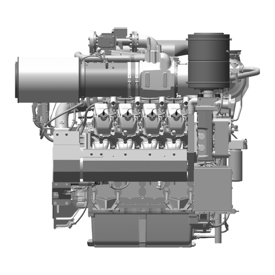
2 Product Summary 2.1 Engine overview 1 Engine governor/engine 5 Engine lifting equipment 9 Engine mounting bracket, monitoring 6 Capacitor discharge igni- driving end 2 Air filter/air inlet tion system 10 Starter 3 Mixture cooler 7 Engine mounting bracket, 11 Flywheel 4 Exhaust turbocharger free end KS Driving end... - Page 20 1 Crankcase breather, oil 7 Spark plug 13 Engine coolant inlet con- separator 8 Cylinder head cover nection 2 Exhaust gas outlet connec- 9 Cylinder head 14 Engine oil heat exchanger tion 10 Engine oil filter 15 Engine coolant outlet con- 3 Gas control valve 11 Engine oil sampling port nection...
-
Page 21: Engine Side And Cylinder Designations
2.2 Engine side and cylinder designations 1 Left engine side (A-side) 3 Right engine side (B-side) 2 Engine free end in accord- 4 Engine driving end in ac- ance with DIN ISO 1204 cordance with (KGS = Kupplungsgegen- DIN ISO 1204 (KS = Kup- seite) plungsseite) Engine sides are always designated (in accordance with DIN ISO 1204) as viewed from driving end (4). -
Page 22: Engine - Main Dimensions
2.3 Engine – Main dimensions Engine – Main dimensions Dimensions Item Length (A) Approx. 2484 mm Width (B) approx. 1743 mm Height (C) approx. 2135 mm Crankshaft center to oil pan (D) approx. 625 mm Crankshaft center to engine mount (E) approx. -
Page 23: Firing Order
2.4 Firing order Firing order Number of cylinders Firing order A1-A3-A4-A2-B3-B4-B2-B1 MS150103/01E 2015-03 | Product Summary | 23... -
Page 24: Technical Data
2.5 Technical Data 2.5.1 8V 4000 L32F engine data, fuel-optimized (TA-Luft) Explanation: DL Ref. value: Continuous power BL Ref. value: Fuel stop power A Design value G Guaranteed value R Guideline value L Limit value, up to which the engine can be operated, without change (e.g. of power settings). N Not yet defined value - Not applicable X Applicable... - Page 25 Number of cylinders Gas type: natural gas Methane number, min. Table 6: General conditions (for maximum power) Consumption Number of cylinders Lube oil consumption after 1000 h runtime g/kWh Table 7: Consumption Model-related data (basic design) Number of cylinders Operating method: Four-stroke cycle, Otto engine, single-acting Combustion method: Mixture charging, spark ignition Number of cylinders Cylinder arrangement: V-angle...
- Page 26 Coolant system (LT circuit) Number of cylinders Coolant temperature before mixture cooler (at engine connection: inlet °C from cooling equipment (w/o antifreeze) Coolant antifreeze content, max. Coolant pump: Volumetric flow m³/h Pressure in cooling system, max. Pressure loss over LT mixture cooler (at nominal flow rate 8.56) Table 10: Coolant system (LT circuit) Lube oil system Number of cylinders...
- Page 27 Number of cylinders Starter current consumption, max. (standard design) 2500 Starting-attempt duration, max. Number of teeth on starter ring gear Table 14: Starter (electric) Capacities Number of cylinders Engine coolant capacity, engine side (w/o cooling equipment) Liters Engine coolant capacity, mixture coolant side (w/o cooling equipment) Liters Total engine oil capacity for initial filling (standard oil system) Liters...
-
Page 28: 4000 L32F Engine Data, Emissions-Optimized (1/2 Ta-Luft)
2.5.2 8V 4000 L32F engine data, emissions-optimized (1/2 TA-Luft) Explanation: DL Ref. value: Continuous power BL Ref. value: Fuel stop power A Design value G Guaranteed value R Guideline value L Limit value, up to which the engine can be operated, without change (e.g. of power settings). N Not yet defined value - Not applicable X Applicable... - Page 29 Consumption Number of cylinders Lube oil consumption after 1000 h runtime g/kWh Table 22: Consumption Model-related data (basic design) Number of cylinders Operating method: four-stroke cycle, Otto engine, single-acting Combustion method: mixture charging, spark ignition Number of cylinders Cylinder arrangement: V-angle Degrees (°) Bore Stroke...
- Page 30 Number of cylinders Coolant pump: volumetric flow m³/h Pressure in cooling system, max. Pressure loss over LT mixture cooler (at nominal flow rate 8.56) Table 25: Coolant system (LT circuit) Lube oil system Number of cylinders Lube oil operating temperature after oil heat exchanger, from °C Lube oil operating temperature after oil heat exchanger, to °C...
- Page 31 Capacities Number of cylinders Engine coolant capacity, engine side (w/o cooling equipment) Liters Engine coolant capacity, mixture cooler side (w/o cooling equipment) Liters Total engine oil capacity for initial filling (standard oil system) Liters Oil change capacity, max. (standard oil system) Liters Table 30: Capacities Weights / main dimensions...
-
Page 32: Monitoring, Control And Regulation Equipment
2.6 Monitoring, Control and Regulation Equipment 2.6.1 Gas engine phase 3 system – Overview General overview 1 Plant system 5 Engine Monitoring Unit 9 Knock module 2 Engine system 6 Humidity sensor (optional) 10 Ignition 3 Plant 7 Throttles 11 Compressor bypass 4 Engine Control Unit 8 Gas dosing unit 12 NOx sensor (optional) - Page 33 Anti-knock control AKR • Controls monitored cylinders with regard to knock characteristics. If knocking is detected, ignition is delayed for the cylinder concerned. The power is reduced if this does not lead to improvement. Gas control valve TecJet52 • Controls the required amount of gas Mixture throttles (P Series) •...
-
Page 34: Purpose Of The Units
2.6.2 Purpose of the units ECU 9 engine governor Central control and monitoring unit for the engine • Communication with other devices and higher-level systems via CAN bus • Control of throttles (mixture and gas) • Registration and analysis of engine operating states •... - Page 35 Engine Monitoring Unit EMU 8 EMU = Engine Monitoring Unit Monitoring unit for the engine • Acquisition and processing of cylinder exhaust temperatures Self-monitoring MS150103/01E 2015-03 | Product Summary | 35...
-
Page 36: Operation
3 Operation 3.1 Runtimes at partial load Gas engines were designed and optimized for continuous operation at 100 % load. The following restrictions apply to ensure maximum operational availability of the engine plant and to reduce maintenance to a minimum: Recommended minimum run- Power, referenced to nominal Recommended maximum run-... -
Page 37: Putting The Engine Into Operation After Extended Out-Of-Service Periods (>3 Months)
3.2 Putting the engine into operation after extended out-of-service periods (>3 months) Preconditions ☑Engine is stopped and starting disabled. ☑MTU Fluids and Lubricants Specifications (A001061/..) are available. Putting the PowerPack into operation after extended out-of-service-periods (>3 months) Item Action Engine Depreserve (→... -
Page 38: Putting The Engine Into Operation After Scheduled Out-Of-Service-Period
3.3 Putting the engine into operation after scheduled out-of- service-period Preconditions ☑Engine shut down and starting disabled. Putting into operation Item Measure Lube oil system Check oil level in oil storage tank (→ Page 153). Coolant circuit Check engine coolant level (→ Page 157); Check mixture coolant level (→... -
Page 39: Control, Starting And Stopping Sequences
3.4 Control, starting and stopping sequences NOTICE Risk of engine damage due to incorrect action. Risk of severe damage to property! • Ensure engine is ready for operation before starting. See engine documentation. Starting and stopping sequences The starting sequence is software-controlled and depends on the place of start command input. To ensure that no mixture is in the engine when ignition is switched on or off, which is a specific re- quirement for gas engines, special procedures for engine start / stop are specified. - Page 40 Emergency stopping sequence If an emergency stop command is activated, the following steps are carried out automatically: 1. Closing gas supply solenoid valves 2. Closing mixture throttles 3. Engine running down to standstill 4. Deactivating ignition 5. Requesting external ventilation by contact Restarting after emergency stop A scavenging phase and a request for external ventilation by contact ensue following a start request after emergency shutdown.
-
Page 41: Engine - Start
3.5 Engine – Start Preconditions ☑Generator not connected to network. ☑Start interlock not active. DANGER Rotating and moving engine parts. Risk of crushing, danger of parts of the body being caught or pulled in! • Before cranking the engine with starter system, make sure that there are no persons in the en- gine's danger zone. -
Page 42: Operational Checks
3.6 Operational checks DANGER Rotating and moving engine parts. Risk of crushing, danger of parts of the body being caught or pulled in! • Only run the engine at low power. Keep away from the engine's danger zone. WARNING High level of engine noise when the engine is running. Risk of damage to hearing! •... -
Page 43: Emission Values - Check
Special tools, Material, Spare parts Designation / Use Part No. Qty. Gas measuring and warning device (not stocked by MTU) DANGER Rotating and moving engine parts. Risk of crushing, danger of parts of the body being caught or pulled in! •... -
Page 44: Engine - Shutdown
3.8 Engine – Shutdown Preconditions ☑Generator is not connected to network. NOTICE Stopping the engine when it is running at full load subjects it to extreme thermal and mechanical stresses. Overheating of and, therefore, damage to components is possible! • Before shutting down the engine, allow it to idle until the engine temperatures decrease and constant levels are indicated. -
Page 45: Emergency Engine Shutdown
3.9 Emergency engine shutdown WARNING Escaping residual gas may create an explosive atmosphere in case of emergency stop. Explosion hazard! • Ensure that any escaping residual gas is routed out by means of appropriate facility ventilation and use of an SBV (safety blow-off valve) to prevent any risk of explosive atmosphere. •... - Page 46 Remedy the cause, re-enable starting Item Action Engine Control System Determine cause of emergency stop and take remedial action; contact Serv- ice if the fault cannot be corrected. Fault acknowledgment is possible in engine stop mode only . Automatic se- lection and remote start immediately following an emergency engine stop is not admissible.
-
Page 47: After Stopping The Engine - Engine Remains Ready For Operation
3.10 After stopping the engine – Engine remains ready for operation After stopping the engine Item Action Engine/generator controller Select operating mode, e.g. MANUAL, AUTOMATIC. (manufacturer-specific) MS150103/01E 2015-03 | Operation | 47... -
Page 48: After Stopping The Engine - Putting The Engine Out Of Operation
If the engine is to remain out of service for more than 1 month, carry out preservation (→ MTU Preservation and Represerva- tion Specifications A001070/..). The corrosion-inhibiting effect of the engine coolant may be used as an alter- native in case of out-of-service periods lasting for more than 1 month, by run- ning the engine for at least 2 hours at rated power once a month. -
Page 49: Maintenance
4 Maintenance 4.1 50-hours check 50-hours check One-time operations to be carried out after a test run or after the first 10 to 50 operating hours of the cylinder head (with a new engine, after installation of new cylinder heads, after component mainte- nance or extended component maintenance). -
Page 50: Maintenance Task Reference Table [Ql1]
4.2 Maintenance task reference table [QL1] The maintenance tasks and intervals for this product are defined in the Maintenance Schedule. The Maintenance Schedule is a stand-alone publication. The task numbers in this table provide reference to the maintenance tasks specified in the Maintenance Schedule. -
Page 51: Troubleshooting
OEM (see documentation of the genset man- ufacturer). A prerequisite for performing the measures to rectify faults is corresponding qualification/training at MTU. Contact Service should troubleshooting as prescribed in the fault code list prove unsuccessful. Recommended action in case of alarm... - Page 52 Red alarm: Caution, the engine is running at its limits. Shut down manually without further delay if the engine does not shut itself down immediately after a red alarm is signaled. 52 | Troubleshooting | MS150103/01E 2015-03...
-
Page 53: Fault Messages In Communication Protocol To Genset Control System
5.2 Fault messages in communication protocol to genset control system 112222 – HI T-Exhaust Mean Yellow alarm. Initiated by EMU. Cause Corrective action Weighted average of all 1. Check emission values. individual exhaust gas 2. Check ignition timing (→ Page 141). temperatures is too high. - Page 54 112305 – HI T-Exhaust A5 Yellow alarm. Initiated by EMU. Cause Corrective action The exhaust temperature of this 1. Check emission values. cylinder is too high as compared 2. Check ignition timing (→ Page 141). with the average value. 3. Check valve drive (exhaust valves do not close). 112306 –...
- Page 55 112311 – HI T-Exhaust B1 Yellow alarm. Initiated by EMU. Cause Corrective action The exhaust temperature of this 1. Check emission values. cylinder is too high as compared 2. Check ignition timing (→ Page 141). with the average value. 3. Check valve drive (exhaust valves do not close). 112312 –...
- Page 56 112317 – HI T-Exhaust B7 Yellow alarm. Initiated by EMU. Cause Corrective action The exhaust temperature of this 1. Check emission values. cylinder is too high as compared 2. Check ignition timing (→ Page 141). with the average value. 3. Check valve drive (exhaust valves do not close). 112318 –...
- Page 57 112403 – LO T-Exhaust A3 Yellow alarm. Initiated by EMU. Cause Corrective action The exhaust temperature of this 1. Check spark plug. cylinder is too high as compared 2. Check emission values. with the average value. 3. Check ignition timing (→ Page 141). 4.
- Page 58 112408 – LO T-Exhaust A8 Yellow alarm. Initiated by EMU. Cause Corrective action The exhaust temperature of this 1. Check spark plug. cylinder is too high as compared 2. Check emission values. with the average value. 3. Check ignition timing (→ Page 141). 4.
- Page 59 112413 – LO T-Exhaust B3 Yellow alarm. Initiated by EMU. Cause Corrective action The exhaust temperature of this 1. Check spark plug. cylinder is too high as compared 2. Check emission values. with the average value. 3. Check ignition timing (→ Page 141). 4.
- Page 60 112418 – LO T-Exhaust B8 Yellow alarm. Initiated by EMU. Cause Corrective action The exhaust temperature of this 1. Check spark plug. cylinder is too high as compared 2. Check emission values. with the average value. 3. Check ignition timing (→ Page 141). 4.
- Page 61 112504 – HIHI T-Exhaust A4 Red alarm. Initiated by EMU. Cause Corrective action The exhaust temperature of this 1. Check emission values. cylinder is too high as compared 2. Check ignition timing (→ Page 141). with the average value. 3. Check valve drive (exhaust valves do not close). 112505 –...
- Page 62 112510 – HIHI T-Exhaust A10 Red alarm. Initiated by EMU. Cause Corrective action The exhaust temperature of this 1. Check emission values. cylinder is too high as compared 2. Check ignition timing (→ Page 141). with the average value. 3. Check valve drive (exhaust valves do not close). 112511 –...
- Page 63 112516 – HIHI T-Exhaust B6 Red alarm. Initiated by EMU. Cause Corrective action The exhaust temperature of this 1. Check emission values. cylinder is too high as compared 2. Check ignition timing (→ Page 141). with the average value. 3. Check valve drive (exhaust valves do not close). 112517 –...
- Page 64 112602 – LOLO T-Exhaust A2 Red alarm. Initiated by EMU. Cause Corrective action The exhaust temperature of this 1. Check spark plug. cylinder is too low as compared 2. Check emission values. with the average value. 3. Check ignition timing (→ Page 141). 4.
- Page 65 112607 – LOLO T-Exhaust A7 Red alarm. Initiated by EMU. Cause Corrective action The exhaust temperature of this 1. Check spark plug. cylinder is too low as compared 2. Check emission values. with the average value. 3. Check ignition timing (→ Page 141). 4.
- Page 66 112612 – LOLO T-Exhaust B2 Red alarm. Initiated by EMU. Cause Corrective action The exhaust temperature of this 1. Check spark plug. cylinder is too low as compared 2. Check emission values. with the average value. 3. Check ignition timing (→ Page 141). 4.
- Page 67 112617 – LOLO T-Exhaust B7 Red alarm. Initiated by EMU. Cause Corrective action The exhaust temperature of this 1. Check spark plug. cylinder is too low as compared 2. Check emission values. with the average value. 3. Check ignition timing (→ Page 141). 4.
- Page 68 112703 – HIHI T-Exhaust A3 (abs) Red alarm. Initiated by EMU. Cause Corrective action Individual exhaust gas 1. Check emission values. temperature of this cylinder is 2. Check ignition timing(→ Page 141). too high. 3. Check valve drive (exhaust valves do not close). 112704 –...
- Page 69 112709 – HIHI T-Exhaust A9 (abs) Red alarm. Initiated by EMU. Cause Corrective action Individual exhaust gas 1. Check emission values. temperature of this cylinder is 2. Check ignition timing (→ Page 141). too high. 3. Check valve drive (exhaust valves do not close). 112710 –...
- Page 70 112715 – HIHI T-Exhaust B5 (abs) Red alarm. Initiated by EMU. Cause Corrective action Individual exhaust gas 1. Check emission values. temperature of this cylinder is 2. Check ignition timing (→ Page 141). too high. 3. Check valve drive (exhaust valves do not close). 112716 –...
- Page 71 112923 – MD/SD T-Exhaust Red alarm. Initiated by EMU. Cause Corrective action u Combined alarm (for details, refer to the source alarm). Combined alarm (for details, refer to the source alarm). 113200 – Communication Lost ECU Red alarm. Initiated by SAM. Cause Corrective action No communication with ECU...
- Page 72 1.4510.188 – Internal Error Red alarm. Initiated by anti-knock control. Cause Corrective action u Restart knock module. Hardware not ready for operation. 1.4510.189 – Error Camshaft Red alarm. Initiated by anti-knock control. Cause Corrective action No signal from camshaft sensor u Check cabling.
- Page 73 1.4510.196 – Knock Sensor Error A5 Red alarm. Initiated by anti-knock control. Cause Corrective action No signal from this knock 1. Check cabling. sensor. 2. Check sensor (tightening torque, damage), replace as necessary. 1.4510.197 – Knock Sensor Error A6 Red alarm. Initiated by anti-knock control. Cause Corrective action No signal from this knock...
- Page 74 1.4510.202 – Knock Sensor Error B1 Red alarm. Initiated by anti-knock control. Cause Corrective action No signal from this knock 1. Check cabling. sensor. 2. Check sensor (tightening torque, damage), replace as necessary. 1.4510.203 – Knock Sensor Error B2 Red alarm. Initiated by anti-knock control. Cause Corrective action No signal from this knock...
- Page 75 1.4510.208 – Knock Sensor Error B7 Red alarm. Initiated by anti-knock control. Cause Corrective action No signal from this knock 1. Check cabling. sensor. 2. Check sensor (tightening torque, damage), replace as necessary. 1.4510.209 – Knock Sensor Error B8 Red alarm. Initiated by anti-knock control. Cause Corrective action No signal from this knock...
- Page 76 1.4520.234 – Error Missing Camshaft Signal Red alarm. Initiated by IC922. Cause Corrective action u Check sensor, sensor distance and cabling, replace as No camshaft signal. necessary. 1.4520.235 – Error Number of Teeth Red alarm. Initiated by IC922. Cause Corrective action Incorrect number of teeth on 1.
- Page 77 1.4520.241 – Individual Timing out of Range Yellow alarm. Initiated by IC922. Cause Corrective action u Adjust value. Specified individual ignition timing is beyond the valid range. 1.4520.242 – Selftest Shutdown Yellow alarm. Initiated by IC922. Cause Corrective action Self-test is active with the u Restart ignition.
- Page 78 1.4520.249 – Open Primary, Channel 5 Yellow alarm. Initiated by IC922. Cause Corrective action Ignition energy was not 1. Check cabling to ignition coil. discharged. 2. Check ignition coils. 1.4520.250 – Open Primary, Channel 6 Yellow alarm. Initiated by IC922. Cause Corrective action Ignition energy was not...
- Page 79 1.4520.256 – Open Primary, Channel 12 Yellow alarm. Initiated by IC922. Cause Corrective action Ignition energy was not 1. Check cabling to ignition coil. discharged. 2. Check ignition coils. 1.4520.257 – Open Primary, Channel 13 Yellow alarm. Initiated by IC922. Cause Corrective action Ignition energy was not...
- Page 80 1.4520.264 – Open Primary, Channel 19 Yellow alarm. Initiated by IC922. Cause Corrective action Ignition energy was not 1. Check cabling to ignition coil. discharged. 2. Check ignition coils. 1.4520.265 – Open Primary, Channel 20 Yellow alarm. Initiated by IC922. Cause Corrective action Ignition energy was not...
- Page 81 1.4520.275 – Odd Energy Level out of Range Yellow alarm. Initiated by IC922. Cause Corrective action u Adjust value. Specified energy level is beyond the valid range. 1.4520.276 – Even Energy Level out of Range Yellow alarm. Initiated by IC922. Cause Corrective action Specified energy level is beyond...
- Page 82 1.4530.012 – Analog Input High Error Yellow alarm. Initiated by F-series. Cause Corrective action u Check setting. F-series setting is incorrect. 1.4530.013 – Analog Input Low Error Yellow alarm. Initiated by F-series. Cause Corrective action F-series setting is incorrect. u Check setting. 1.4530.014 –...
- Page 83 1.4530.019 – Run Enable not active Yellow alarm. Initiated by F-series. Cause Corrective action u Check setting. F-series setting is incorrect. 1.4530.020 – Spring Check Failed Yellow alarm. Initiated by F-series. Cause Corrective action F-series setting is incorrect. u Check setting. 1.4530.021 –...
- Page 84 1.4540.012 – Valve Position Error Red alarm. Initiated by TecJet. Cause Corrective action u Restart TecJet. Hardware not ready for operation. 1.4540.013 – High Elec Temp Red alarm. Initiated by TecJet. Cause Corrective action Hardware not ready for u Restart TecJet. operation.
- Page 85 1.4540.019 – Position Fail High Red alarm. Initiated by TecJet. Cause Corrective action u Restart TecJet. Hardware not ready for operation. 1.4540.020 – Elec Temp Fail Low Red alarm. Initiated by TecJet. Cause Corrective action Hardware not ready for u Restart TecJet. operation.
- Page 86 1.4540.026 – Analog Input Low Error Red alarm. Initiated by TecJet. Cause Corrective action u Check setting. TecJet setting is not correct. 1.4540.027 – Analog Input High Error Red alarm. Initiated by TecJet. Cause Corrective action TecJet setting is not correct. u Check setting.
- Page 87 1.4540.033 – Battery Volt High Error Red alarm. Initiated by TecJet. Cause Corrective action Supply voltage has reached 1. Check supply voltage. maximum limit value. 2. Check cabling. 1.4540.034 – FGT High Limit Error Red alarm. Initiated by TecJet. Cause Corrective action Hardware not ready for u Restart TecJet.
- Page 88 1.4540.041 – TecJet Internal Fault Red alarm. Initiated by TecJet. Cause Corrective action u Restart TecJet. Hardware not ready for operation. 1.4540.042 – Keyswitch State Red alarm. Initiated by TecJet. Cause Corrective action Keyswitch cabling missing. u Check cabling. 1.4540.043 – Parameter Error Red alarm.
- Page 89 1.4540.048 – SPI ADC Error Red alarm. Initiated by TecJet. Cause Corrective action u Restart TecJet. Hardware not ready for operation. 1.4540.049 – Sense 5V Error Red alarm. Initiated by TecJet. Cause Corrective action Hardware not ready for u Restart TecJet. operation.
- Page 90 1.4540.055 – Factory CAL Error Red alarm. Initiated by TecJet. Cause Corrective action u Restart TecJet. Hardware not ready for operation. 1.4540.056 – PWM Duty Cycle High Error Red alarm. Initiated by TecJet. Cause Corrective action TecJet setting is not correct. u Check setting.
- Page 91 1.4550.036 – A - Temperature derating active Yellow alarm. Initiated by ProAct A-Bank. Cause Corrective action The internal temperature is 1. Check temperature in room. Restart ProAct. higher than the limit. 2. Restart ProAct. 1.4550.037 – A - Temperature above 120 °C Red alarm.
- Page 92 1.4550.043 – A - CAN Fault (CAN Bus Off, CAN Ad) Red alarm. Initiated by ProAct A-Bank. Cause Corrective action u Check cabling and setting. CAN bus connection faulty. 1.4550.044 – A - CAN Stop Command Yellow alarm. Initiated by ProAct A-Bank. Cause Corrective action “Stop”...
- Page 93 1.4550.136 – B - Temperature derating active Yellow alarm. Initiated by ProAct B-Bank. Cause Corrective action The internal temperature is 1. Check temperature in room. Restart ProAct. higher than the limit. 2. Restart ProAct. 1.4550.137 – A - Temperature above 120 °C Red alarm.
- Page 94 1.4550.143 – B - CAN Fault (CAN Bus Off, CAN Ad) Red alarm. Initiated by ProAct B-Bank. Cause Corrective action u Check cabling and setting. CAN bus connection faulty. 1.4550.144 – B - CAN Stop Command Yellow alarm. Initiated by ProAct B-Bank. Cause Corrective action “Stop”...
-
Page 95: Fault Messages - Engine Control Unit
5.3 Fault messages – Engine Control Unit 015 – LO P-Lube Oil Yellow alarm. Associated parameter 2.0100.921 Cause Corrective action Engine oil pressure too low (limit 1. Check oil system, oil heat exchanger. value 1). No oil in engine, engine 2. - Page 96 021 – HI T-Exhaust B Yellow alarm. Associated parameter 2.0127.931 Cause Corrective action Exhaust gas temperature (B 1. Check exhaust turbocharger. side) after turbine too high (limit 2. Check ignition timing (→ Page 141). value 1). Incorrect ignition 3. Check mixture setting. timing, mixture too lean or too 4.
- Page 97 030 – SS Engine Overspeed Red alarm. Engine shutdown. Associated parameter 2.2510.932 Cause Corrective action Overspeed detected by ECU. 1. Check governor. This usually fault message 2. Check throttle closing position. usually follows other fault messages. Check governor, throttle closing position. 031 –...
- Page 98 051 – HI T-Lube Oil Yellow alarm. Associated parameter 2.0125.931 Cause Corrective action Engine oil temperature after oil 1. Check engine coolant circuit. heat exchanger too high (limit 2. Check oil heat exchanger. value 1). Oil heat exchanger 3. Check oil level (→ Page 153). contaminated, coolant temperature too high.
- Page 99 058 – SS P-Coolant Red alarm. Engine shutdown. Associated parameter 2.0101.922 Cause Corrective action u Check engine coolant circuit (pressure and flow). Coolant pressure after engine too low (limit value 2). Insufficient volume flow, static pressure too low. 063 – HI P-Crankcase Yellow alarm.
- Page 100 068 – SS T-Coolant Red alarm. Engine shutdown. Associated parameter 2.0120.932 Cause Corrective action u Check engine coolant circuit. Coolant temperature after engine too high (limit value 2). Engine coolant pump failure, volumetric flow too low, air in engine coolant circuit. 089 –...
- Page 101 092 – SS Starter Speed Not Reached Red alarm. Start terminated. Associated parameter 2.1090.923 Cause Corrective action u Check starter system. Minimum speed for flushing process and ignition release was not attained. 093 – SS T-Preheat Red alarm. Engine shutdown. Associated parameter 2.1090.922 Cause Corrective action...
- Page 102 118 – LO ECU Power Supply Voltage Yellow alarm. Associated parameter 2.0140.921 Cause Corrective action Supply voltage too low (limit 1. Check supply voltage. value 1). 2. Check cabling. 119 – LOLO ECU Power Supply Voltage Red alarm. Associated parameter 2.0140.922 Cause Corrective action Supply voltage too low (limit...
- Page 103 181 – AL CAN2 Node Lost Yellow alarm. Associated parameter 2.0500.681 Cause Corrective action u Check operation of bus stations and cabling. Buses (CAN bus 1 Bus node (SAM or EMU) lost on CAN bus 2. and CAN bus 2) are redundant. 182 –...
- Page 104 187 – AL CAN1 Error Passive Yellow alarm. Associated parameter 2.0500.687 Cause Corrective action u Check operation of bus stations and cabling. CAN controller 1 has indicated a warning. Bus users (ECU, SAM or EMU) are faulty. 188 – AL CAN2 Bus Off Yellow alarm.
- Page 105 204 – SD Level Lube Oil Red alarm. Engine shutdown. Associated parameter 1.8004.602 Cause Corrective action u Check sensor and cabling (B24), replace as necessary. Fault is Engine oil level sensor defective, short circuit or wire break. rectified following engine restart. 206 –...
- Page 106 214 – SD P-Crankcase Red alarm. Associated parameter 1.8004.568 Cause Corrective action u Check sensor and cabling (B50), replace as necessary. Fault is Crankcase pressure sensor defective, short circuit or wire rectified following engine restart. break. 216 – SD T-Lube Oil Red alarm.
- Page 107 229 – AL Stop Camshaft Sensor Defect Red alarm. Engine shutdown. Associated parameter 1.8004.562 Cause Corrective action u Check sensor and cabling (B1.1), replace as necessary. Fault is Engine stop due to camshaft sensor fault (and a previous rectified following engine restart. crankshaft sensor fault in the same operating cycle).
- Page 108 266 – SD Speed Demand Red alarm. Associated parameter 2.8006.586 Cause Corrective action u Check signal and cabling between plant and ADEC. Speed setting signal can no longer be transmitted from plant. 381 – AL Wiring TOP 1 Yellow alarm. Associated parameter 2.8006.638 Cause Corrective action...
- Page 109 418 – SD T-Intake Air B Yellow alarm. Associated parameter 1.8004.603 Cause Corrective action u Check sensor and cabling (B49.2), replace as necessary. Intake air temperature sensor defective, short circuit or wire break. 419 – SD T-Coolant before Engine Red alarm. Associated parameter 1.8004.604 Cause Corrective action...
- Page 110 431 – SS P-Coolant before Engine Red alarm. Engine shutdown. Associated parameter 2.0168.922 Cause Corrective action u Check engine coolant circuit (pressure and flow). Coolant pressure before engine too low (limit value 2). Insufficient volume flow, static pressure too low. 434 –...
- Page 111 447 – HIHI P-Charge Mix Diff. Red alarm. Engine shutdown. Associated parameter 2.0183.932 Cause Corrective action Difference in mixture pressures 1. Check throttles for varying positions and malfunction. sensed on A and B side is too 2. Check mixture lines for leakage. high (limit value 2).
- Page 112 457 – LO T-Intake Air Yellow alarm. Associated parameter 2.0123.921 Cause Corrective action u Check ventilation system. Intake air temperature is too low (limit value 3). 458 – LOLO T-Intake Air Red alarm. Engine shutdown. Associated parameter 2.0123.922 Cause Corrective action Intake air temperature is too low u Check ventilation system.
- Page 113 478 – AL Comb. Alarm Yel (Plant) Yellow alarm. Associated parameter 2.8006.001 Cause Corrective action u Combined alarm (for details, refer to the source alarm). Combined YELLOW alarm from plant. 479 – AL Comb. Alarm Red (Plant) Red alarm. Engine shutdown. Associated parameter 2.8006.002 Cause Corrective action...
- Page 114 499 – SD T-Charge Mix Red alarm. Associated parameter 1.8004.632 Cause Corrective action u Check sensor and cabling (B73), replace as necessary. Fault is Mixture temperature sensor defective, short circuit or wire rectified following engine restart. break. 511 – HIHI P-Charge Mix A Red alarm.
- Page 115 517 – SD P-Charge Mix before Throttle Red alarm. Associated parameter 1.8004.631 Cause Corrective action u Check sensor and cabling (B79.23), replace as necessary. Fault Mixture pressure sensor before throttle defective, short circuit is rectified following engine restart. or wire break. 520 –...
- Page 116 554 – AL Ignition Fault Red alarm. Associated parameter 2.1090.122 Cause Corrective action Ignition failure. Alarm is 1. Check ignition system. activated if the feedback signal 2. Check cabling. from ignition system is not received within a specified time- out period. Either the ignition could not be activated, the timeout period is set too short, or communication is faulty.
- Page 117 560 – Mixture throttle B Red alarm. Engine shutdown. Associated parameter 1.1450.013 Cause Corrective action u Check mixture throttle on B side and cabling. Replace mixture A problem related to mixture throttle on B side occurred. throttle on B side as necessary. Possible causes: Mixture throttle defective, no power supply to throttle, cabling of feedback...
- Page 118 569 – AL SAM Missing Data Fault Red alarm. Associated parameter 2.1090.128 Cause Corrective action u Check the cabling/connectors of the devices connected to This alarm is activated if the ECU does not receive some SAM and ECU bus. Replace devices as necessary. messages to be transmitted from SAM.
- Page 119 583 – AL GLS closed Red alarm. Engine shutdown. Associated parameter 2.0451.115 Cause Corrective action Generator load switch does not 1. Check generator load switch. open when engine stops. Engine 2. Manually disconnect generator switch. is motoring. 3. Open any existing mains circuit breaker. 4.
- Page 120 620 – HIHI Current Heat Value of Fuel Yellow alarm. Associated parameter 2.1210.009 Cause Corrective action u Check gas quality if feasible. Fuel calorific value has undershot the second limit value. 621 – LO NOx Value Yellow alarm. Associated parameter 2.3050.024 Cause Corrective action NOx emissions have undershot...
- Page 121 633 – SD P-Ambient Air (HDT2800) none Associated parameter 1.0700.087 Cause Corrective action u Sensor currently not in standard scope of delivery. Air humidity sensor defect. 634 – SD T0-Ambient Air (HDT2800) none Associated parameter 1.0700.089 Cause Corrective action Air humidity sensor defect. u Sensor currently not in standard scope of delivery.
- Page 122 650 – Al Req Angle Throttle B Red alarm. Associated parameter 2.1200.936 Cause Corrective action Opening angle of throttles B 1. Check charge-air pressure reserve. exceeded. 2. Intake air temperature outside TVU data. 3. Check compressor for contamination. 4. Reduce power. 651 –...
- Page 123 655 – AL TecJet Comm Lost Red alarm. Associated parameter 1.4540.996 Cause Corrective action CAN bus communication for gas 1. Check cabling. control valve faulty 2. Check power supply. (alternatively, a stepper motor 3. Carry out restart of ECU, EMU & gas control valve. with gas mixer can be installed).
- Page 124 664 – AL Oil Refill Error Red alarm. Associated parameter 1.1480.305 Cause Corrective action u After initiation of the alarms “HI Oil Refill” and Combined alarm for automatic oil replenishment faulty. “HI Lube Oil Level refill” a programmable timeout period starts. The engine is stopped when this time expires.
- Page 125 669 – AL ProActA Yellow Yellow alarm. Associated parameter 1.4550.093 Cause Corrective action u An exact fault designation is transmitted via CAN bus to the An internal combined alarm in throttle A was detected. genset control system. 670 – AL ProActB Yellow Yellow alarm.
- Page 126 677 – AL FSeries Red Red alarm. Associated parameter 1.4530.991 Cause Corrective action u An exact fault designation is transmitted via CAN bus to the An internal combined alarm in the bypass flap was detected. genset control system. 678 – AL TecJet Red Red alarm.
- Page 127 685 – AL Lube Oil Min Red alarm. Associated parameter 1.1480.307 Cause Corrective action Minimum engine oil filling level 1. Check engine oil level (→ Page 153). detected. 2. Check replenishment system. 3. Fill oil. 686 – AL Lube Oil Max Red alarm.
- Page 128 694 – SD T-Gas Yellow alarm. Associated parameter 1.8004.123 Cause Corrective action Gas temperature sensor 1. Not installed in all engine versions (optional). defective, short circuit or wire 2. Check sensor and cabling (B38), replace as necessary. break. 719 – AL T-Gas L1 Yellow alarm.
-
Page 129: Task Description
6 Task Description 6.1 Engine 6.1.1 Engine – Barring manually Preconditions ☑Engine is stopped and starting disabled. Special tools, Material, Spare parts Designation / Use Part No. Qty. Barring gear F6555766 Ratchet head with extension F30006212 DANGER Rotating and moving engine parts. Risk of crushing, danger of parts of the body being caught or pulled in! •... -
Page 130: Machine Room - Check For Smell Of Gas
6.1.2 Machine room – Check for smell of gas Special tools, Material, Spare parts Designation / Use Part No. Qty. Gas detection and alarm unit (not stocked by MTU) WARNING Gaseous fuels are combustible/explosive. Risk of fire and explosion! • Avoid open flames, electrical sparks and ignition sources. -
Page 131: Crankcase Breather
6.2 Crankcase Breather 6.2.1 Oil separator – Filter replacement Preconditions ☑Engine is stopped and starting disabled. Special tools, Material, Spare parts Designation / Use Part No. Qty. Filter element (→ Spare Parts Catalog) Sealing ring (→ Spare Parts Catalog) O-ring (→... - Page 132 Remove locknut (1). Remove filter cover (3) with washer (2). Carefully lift out fine filter (6). Carefully lift out coalescence filter (5). Clean sealing faces and inside of housing. Check condition of gaskets on new fine fil- ter and new coalescence filter. Note: The fine filter (6) must be installed in the correct position in the housing.
-
Page 133: Ignition System
6.3 Ignition System 6.3.1 Spark plug – Replacement Special tools, Material, Spare parts Designation / Use Part No. Qty. Spark plug (→ Spare Parts Catalog) Replacing spark plug Remove spark plug (→ Page 134). Install new spark plug (→ Page 135). MS150103/01E 2015-03 | Task Description | 133... -
Page 134: Spark Plug - Removal
6.3.2 Spark plug – Removal Preconditions ☑Engine is stopped and starting disabled. ☑Open protective packing of new spark plug only immediately prior to installation. Special tools, Material, Spare parts Designation / Use Part No. Qty. Special wrench, 20.8 mm F30452574 WARNING Hot components/surfaces. -
Page 135: Spark Plug - Installation
6.3.3 Spark plug – Installation Preconditions ☑Engine is stopped and starting disabled. ☑Open protective packing of new spark plug only immediately prior to installation. Special tools, Material, Spare parts Designation / Use Part No. Qty. Torque wrench, 10-60 Nm F30452769 Special wrench, 20.8 mm F30452574 Assembly compound (Molykote P 37) - Page 136 Screw spark plug into cylinder head. Note: The temperature of spark plug and cylinder head must be the same prior to tightening. Tighten spark plug to specified torque using a torque wrench. Name Size Type Lubricant Value/Standard Spark plug M18 x 1.5 Tightening torque (Assembly compound 50 +5 Nm (Molykote P 37))
-
Page 137: Spark Plug Connector - Replacement
6.3.4 Spark plug connector – Replacement Special tools, Material, Spare parts Designation / Use Part No. Qty. Spark plug connector (→ Spare Parts Catalog) Replacing spark plug connector Remove spark plug connector (→ Page 138). Install spark plug connector (→ Page 139). MS150103/01E 2015-03 | Task Description | 137... -
Page 138: Spark Plug Connector - Removal
6.3.5 Spark plug connector – Removal Preconditions ☑Engine is stopped and starting disabled. ☑Open protective packing of new spark plug connector only immediately prior to installation. WARNING Hot components/surfaces. Risk of burns! • Allow the engine to cool down to below 50 °C before beginning work. •... -
Page 139: Spark Plug Connector - Installation
6.3.6 Spark plug connector – Installation Preconditions ☑Engine is stopped and starting disabled. ☑Open protective packing of new spark plug connector only immediately prior to installation. Special tools, Material, Spare parts Designation / Use Part No. Qty. Torque wrench, 10-60 Nm F30452769 Spark plug connector with ignition line (→... - Page 140 Exchanging spark plug isolator sealing ring Insert screwdriver (3) between Teflon sleeve (1) and sealing ring (2). Pry out and pull out sealing ring (2). Fold together new sealing ring (2). Insert sealing ring (2) into the bore in Tef- lon sleeve (1) with the article number fac- ing downwards.
-
Page 141: Ignition System - Ignition Timing Check
Special tools, Material, Spare parts Designation / Use Part No. Qty. Stroboscope (Not stocked by MTU) DANGER Live components, flash-over. Risk of serious injury - danger to life! • Always wear electrical gloves (class 4 minimum) when touching the ignition cable in operation. -
Page 142: Valve Drive
6.4 Valve Drive 6.4.1 Valve projection – Measurement Preconditions ☑Engine is stopped and starting disabled. Special tools, Material, Spare parts Designation / Use Part No. Qty. Sliding depth gauge, 200 mm Y20000918 Preparatory steps Remove spark plugs (→ Page 134). Remove cylinder head covers (→... - Page 143 Measuring valve projection Check TDC position of piston in cylinder A1: • If the rocker arms are unloaded on cylinder A1, the piston is in firing TDC. • If the rocker arms are under load on cylinder A1, the piston is in overlap TDC. Measure valve projection for each valve in two crankshaft positions (firing TDC and overlap TDC for cyl- inder A1) according to the diagram.
- Page 144 Install sleeves (arrow). Install cylinder head covers (→ Page 149). Install spark plugs with new sealing rings (→ Page 135). 144 | Task Description | MS150103/01E 2015-03...
-
Page 145: Valve Clearance - Check And Adjustment
6.4.2 Valve clearance – Check and adjustment Preconditions ☑Engine is stopped and starting disabled. ☑Engine coolant temperature is max. 40 °C. ☑Valves are closed. Special tools, Material, Spare parts Designation / Use Part No. Qty. Feeler gauge Y20098771 Angular screw driver F30452765 Torque wrench, 60–320 Nm F30452768... - Page 146 Valve clearance at two crankshaft positions – Check Check TDC position of piston in cylinder A1: • If rocker arms on cylinder A1 are unloaded, the piston is in firing TDC. • If rocker arms on cylinder A1 are loaded, the piston is in overlap TDC. Check valve clearance adjustment with cold engine: •...
-
Page 147: Valve Gear - Lubrication
6.4.3 Valve gear – Lubrication Preconditions ☑Engine is stopped and starting disabled. Special tools, Material, Spare parts Designation / Use Part No. Qty. Engine oil Lubricating valve gear Remove cylinder head covers (→ Page 148). Fill oil chambers of rocker arms and adjust- ing screws with oil. -
Page 148: Cylinder Head Cover - Removal
6.4.4 Cylinder head cover ‒ Removal Preconditions ☑Engine is stopped and starting disabled. Cylinder head cover ‒ Removal Clean very dirty cylinder head covers (1) prior to removal. Remove spark plug connector (→ Page 138). Remove screws (2). Remove cylinder head cover with gasket from cylinder head. -
Page 149: Cylinder Head Cover - Installation
6.4.5 Cylinder head cover ‒ Installation Special tools, Material, Spare parts Designation / Use Part No. Qty. Gasket (→ Spare Parts Catalog) NOTICE Contamination of components. Damage to component! • Observe manufacturer's instructions. • Check components for special cleanliness. Cylinder head cover ‒ Installa- tion Clean mounting surface. -
Page 150: Gas System
6.5 Gas System 6.5.1 Gas supply – Checking gas lines for leaks Preconditions ☑Engine is stopped and starting disabled. Special tools, Material, Spare parts Designation / Use Part No. Qty. Leak identification spray Soap suds WARNING Gaseous fuels are combustible/explosive. Risk of fire and explosion! •... -
Page 151: Air Filter
6.6 Air Filter 6.6.1 Air filter – Replacement Special tools, Material, Spare parts Designation / Use Part No. Qty. Air filter (→ Spare Parts Catalog) Prefilter made of fleece (option) (→ Spare Parts Catalog) Note: Air filter condition is monitored by a sensor. Replace air filter and/or (optional) fleece prefilter when the corresponding fault message appears. -
Page 152: Air Filter - Removal And Installation
6.6.2 Air filter – Removal and installation Preconditions ☑Engine is stopped and starting disabled. Air filter – Removal and installa- tion Loosen clamp (2). Remove air filter (3) and clamp (2) from connecting flange (1) of intake housing. Clean connecting flange (1) of the intake housing and check for obstructions. -
Page 153: Lube Oil System, Lube Oil Circuit
6.7 Lube Oil System, Lube Oil Circuit 6.7.1 Engine oil – Level check Preconditions ☑Engine is stopped and starting disabled. WARNING Hot oil. Oil can contain combustion residues which are harmful to health. Risk of injury and poisoning! • Wear protective clothing, gloves, and goggles / safety mask. •... -
Page 154: Engine Oil - Change
6.7.2 Engine oil – Change Preconditions ☑Engine is stopped and starting disabled. ☑Engine is at operating temperature. ☑MTU Fluids and Lubricants Specifications (A001061/..) are available. Special tools, Material, Spare parts Designation / Use Part No. Qty. Engine oil WARNING Hot oil. -
Page 155: Engine Oil - Sample Extraction And Analysis
6.7.3 Engine oil – Sample extraction and analysis Preconditions ☑MTU Fluids and Lubricants Specifications (A001061/..) are available. DANGER Rotating and moving engine parts. Risk of crushing, danger of parts of the body being caught or pulled in! • Only run the engine at low power. Keep away from the engine's danger zone. -
Page 156: Oil Filtration / Cooling
6.8 Oil Filtration / Cooling 6.8.1 Engine oil filter – Replacement Preconditions ☑Engine is stopped and starting disabled. Special tools, Material, Spare parts Designation / Use Part No. Qty. Oil filter wrench F30379104 Engine oil Oil filter (→ Spare Parts Catalog) WARNING Hot oil. -
Page 157: Circuit
6.9 Coolant Circuit, General, High-Temperature Circuit 6.9.1 Engine coolant – Level check Preconditions ☑Engine is stopped and starting disabled. ☑MTU Fluids and Lubricants Specifications (A001061/..) are available. WARNING Coolant is hot and under pressure. Risk of injury and scalding! • Let the engine cool down. -
Page 158: Engine Coolant – Change
6.9.2 Engine coolant – Change Special tools, Material, Spare parts Designation / Use Part No. Qty. Coolant Engine coolant change Drain engine coolant (→ Page 159). Fill with engine coolant (→ Page 161). 158 | Task Description | MS150103/01E 2015-03... -
Page 159: Engine Coolant – Draining
6.9.3 Engine coolant – Draining Preconditions ☑Engine is stopped and starting disabled. Special tools, Material, Spare parts Designation / Use Part No. Qty. Sealing ring (→ Spare Parts Catalog) WARNING Coolant is hot and under pressure. Risk of injury and scalding! •... - Page 160 Draining of residual coolant: • At coolant distribution housing. Close all open drain points. 160 | Task Description | MS150103/01E 2015-03...
-
Page 161: Engine Coolant – Filling
6.9.4 Engine coolant – Filling Preconditions ☑Engine is stopped and starting disabled. ☑MTU Fluids and Lubricants Specifications (A001061/..) are available. Special tools, Material, Spare parts Designation / Use Part No. Qty. Engine coolant WARNING Coolant is hot and under pressure. -
Page 162: Vent Line Of Engine Coolant Circuit Replacement
6.9.5 Vent line of engine coolant circuit – Replacement Preconditions ☑Engine is stopped and starting disabled. WARNING Coolant is hot and under pressure. Risk of injury and scalding! • Let the engine cool down. • Wear protective clothing, gloves, and goggles / safety mask. Replacing coolant vent line Drain engine coolant (→... -
Page 163: Low-Temperature Circuit
6.10 Low-Temperature Circuit 6.10.1 Mixture coolant level – Check Preconditions ☑Engine is stopped and starting disabled. ☑MTU Fluids and Lubricants Specifications (A001061/..) are available. WARNING Coolant is hot and under pressure. Risk of injury and scalding! • Let the engine cool down. -
Page 164: Mixture Coolant – Change
6.10.2 Mixture coolant – Change Special tools, Material, Spare parts Designation / Use Part No. Qty. Mixture coolant Mixture coolant – Change Drain mixture coolant (→ Page 165). Fill with fresh mixture coolant (→ Page 166). 164 | Task Description | MS150103/01E 2015-03... -
Page 165: Mixture Coolant – Draining
6.10.3 Mixture coolant – Draining Preconditions ☑Engine is stopped and starting disabled. WARNING Coolant is hot and under pressure. Risk of injury and scalding! • Let the engine cool down. • Wear protective clothing, gloves, and goggles / safety mask. Draining mixture coolant Provide a suitable receptacle to catch the coolant. -
Page 166: Mixture Coolant – Filling
6.10.4 Mixture coolant – Filling Preconditions ☑Engine is stopped and starting disabled. ☑MTU Fluids and Lubricants Specifications (A001061/..) are available. Special tools, Material, Spare parts Designation / Use Part No. Qty. Mixture coolant WARNING Coolant is hot and under pressure. -
Page 167: Wiring (General) For Engine/Gearbox/Unit
6.11 Wiring (General) for Engine/Gearbox/Unit 6.11.1 Engine cabling – Check Preconditions ☑Engine is stopped and starting disabled. Special tools, Material, Spare parts Designation / Use Part No. Qty. Solvent (isopropyl alcohol) X00058037 Engine cabling – Check Check securing screws of cable clamps on engine and tighten loose screw connections. Ensure that cables are securely seated in clamps and cannot move freely. -
Page 168: Sensors – Overview
6.11.2 Sensors – Overview Sensors, B side Item Name Monitoring of B49.2 Intake air temperature, B side B81.2 Intake air pressure after filter, B side B16.1 Coolant pressure after engine B4.X Exhaust temperature after cylinder B79.22 Mixture pressure, B side Mixture temperature Table 40: Sensors, B side Knock sensors (B80.XX) are arranged on crankcase (right and left) below cylinder heads. - Page 169 Sensors, driving end Item Name Monitoring of Nitric oxide values in exhaust gas (NOx) B79.23 Mixture pressure before throttle Crankshaft speed reset B13.3 Crankshaft speed ignition system Table 41: Sensors, driving end MS150103/01E 2015-03 | Task Description | 169...
- Page 170 Sensors, A side Item Name Monitoring of B44.1 Turbocharger speed (optional) B79.21 Mixture pressure, A side Crankcase pressure B5.1 Engine oil pressure after filter B5.3 Engine oil pressure before filter Engine oil temperature Table 42: Sensors, A side 170 | Task Description | MS150103/01E 2015-03...
- Page 171 Sensors, free end Item Name Monitoring of B4.21 Combined exhaust temperature, A side B16.3 Coolant pressure before engine B1.3 Camshaft speed knock module B1.2 Camshaft speed ignition system B1.1 Camshaft speed engine governor Engine oil level B6.3 Coolant temperature before engine B6.1 Coolant temperature after engine Table 43: Sensors, free end...
-
Page 172: Sensors – Removal
6.11.3 Sensors – Removal Preconditions ☑Preparatory steps have been completed. ☑Provide containers for catching any fluids that escape. Special tools, Material, Spare parts Designation / Use Part No. Qty. Ratchet adapter F30027340 WARNING Fuels are combustible. Risk of fire and explosion! •... - Page 173 Removing NOx sensor (B88) Observe the following general information: • Arrangement and position of sensor (→ Page 168). Unfasten electrical connector (2) and re- move. Unscrew electronics box (1) at the eyelets. Remove sensor via nut (3). MS150103/01E 2015-03 | Task Description | 173...
-
Page 174: Sensor – Installation
6.11.4 Sensor – Installation Special tools, Material, Spare parts Designation / Use Part No. Qty. Torque wrench, 10–60 Nm F30452769 Ratchet adapter F30027340 Assembly compound (Kluthe Hakuform 30-15) X00067260 O-ring (→ Spare Parts Catalog) Sealing ring (→ Spare Parts Catalog) Sealing ring (→... -
Page 175: Abbreviations
American National Standards Institute Association of American standardization organ- izations Exhaust turbocharger Series Betriebsstoffvorschrift MTU Publication No. A01061/.. Controller Area Network Data bus system, bus standard Circuit Deutsches Institut für Normung e. V. At the same time identifier of German stand- ards (DIN = “Deutsche Industrie-Norm”) - Page 176 Explanation Abbreviation Meaning ORFS O-Ring Face Seal O-ring seal Top Dead Center Panel Control panel Peripheral Interface Module Peripheral interface module Pulse Width Modulation Modulated signal Redundancy Lost Alarm: Redundant CAN bus failure Society of Automotive Engineers U.S. standardization organization Sicherheitsabsperrventil Sicherheitsabbalseventil Sensor Defect...
-
Page 177: Partner
Local Support Experienced and qualified specialists place their knowledge and expertise at your disposal. For our locally available support, go to MTU's Internet site: • http://www.mtuonsiteenergy.com/haendlersuche/index.de.html 24-h Hotline With our 24-h hotline and the flexibility of our service staff, we are always ready to assist you - either during operation, for preventive maintenance, corrective work in case of malfunction or changed oper- ating conditions, or for spare parts supply. -
Page 178: Special Tools
Y20098771 Qty.: Used in: 6.4.2 Valve clearance – Check and adjustment (→ Page 145) Gas detection and alarm unit (not stocked by MTU) Part No.: Qty.: Used in: 6.1.2 Machine room – Check for smell of gas (→ Page 130) - Page 179 Gas measuring and warning device (not stocked by MTU) Part No.: Qty.: Used in: 3.7 Emission values – Check (→ Page 43) Oil filter wrench Part No.: F30379104 Qty.: Used in: 6.8.1 Engine oil filter – Replacement (→ Page 156) Ratchet adapter Part No.:...
- Page 180 Used in: 6.3.2 Spark plug – Removal (→ Page 134) Qty.: Used in: 6.3.3 Spark plug – Installation (→ Page 135) Stroboscope (Not stocked by MTU) Part No.: Qty.: Used in: 6.3.7 Ignition system – Ignition timing check (→ Page 141)
- Page 181 Torque wrench, 10-60 Nm Part No.: F30452769 Qty.: Used in: 6.3.3 Spark plug – Installation (→ Page 135) Qty.: Used in: 6.3.6 Spark plug connector – Installation (→ Page 139) Torque wrench, 10–60 Nm Part No.: F30452769 Qty.: Used in: 6.11.4 Sensor –...
-
Page 182: Index
– Protocol to genset control system 53 Cabling Firing order 23 – Check – On engine 167 Contact person Gas engine phase 3 system – MTU Onsite Energy 177 – Overview 32 Control 39 Gas supply Coolant – Check – Change 158 –... - Page 183 – Startup, special instructions for applications with gas- eous fuel 10 Sensors – Installation 174 – Overview 168 – Removal 172 Service partner – MTU Onsite Energy 177 Spark plug – Installation 135 – Removal 134 – Replacement 133 Spark plug connector – Installation 139...
Need help?
Do you have a question about the 8V 4000 Lx2 x and is the answer not in the manual?
Questions and answers