Siemens SCALANCE X-300 Series Operating Instructions Manual
Industrial ethernet switches
Hide thumbs
Also See for SCALANCE X-300 Series:
- Configuration manual (404 pages) ,
- Manual (290 pages) ,
- Compact operating instructions (84 pages)
Table of Contents
Advertisement
Quick Links
SIMATIC NET
Industrial Ethernet Switches
SCALANCE X-300
Operating Instructions
11/2019
A5E01113043-24
Introduction
Safety instructions
Recommendations on
network security
Network topologies
Description of the device
Installation
Connecting
Configuration, displays and
display elements
Technical specifications
Accessories
Graphics
Certifications and approvals
Appendix
1
2
3
4
5
6
7
8
9
10
11
A
Advertisement
Table of Contents

Related Manuals for Siemens SCALANCE X-300 Series


Summary of Contents for Siemens SCALANCE X-300 Series
- Page 1 Introduction Safety instructions Recommendations on network security SIMATIC NET Network topologies Industrial Ethernet Switches SCALANCE X-300 Description of the device Installation Operating Instructions Connecting Configuration, displays and display elements Technical specifications Accessories Graphics Certifications and approvals Appendix 11/2019 A5E01113043-24...
- Page 2 Note the following: WARNING Siemens products may only be used for the applications described in the catalog and in the relevant technical documentation. If products and components from other manufacturers are used, these must be recommended or approved by Siemens. Proper transport, storage, installation, assembly, commissioning, operation and maintenance are required to ensure that the products operate safely and without any problems.
-
Page 3: Introduction
Introduction Purpose of the Operating Instructions These operating instructions support you when installing and connecting up devices of the SCALANCE X-300 product group. Validity of the Operating Instructions These operating instructions apply to the following devices: ● SCALANCE X‑300 ● SCALANCE X‑300M ●... - Page 4 Introduction Overview of technical documentation on the IE switches SCALANCE X‑300 You will find the technical documentation for the SCALANCE X‑300 product line in the following documents: ● Configuration manual (PH), available as PDF document The configuration manual describes the software for the two product lines SCALANCE X‑300 and SCALANCE X‑400.
- Page 5 You will find the Configuration Manual here: ● On the data medium that ships with some products: – Product CD / product DVD – SIMATIC NET Manual Collection ● On the Internet pages of Siemens Industry Online Support (https:// support.industry.siemens.com/cs/ww/en/ps/15297/man). Additional documentation The manual ●...
- Page 6 In order to protect plants, systems, machines and networks against cyber threats, it is necessary to implement – and continuously maintain – a holistic, state-of-the-art industrial security concept. Siemens’ products and solutions constitute one element of such a concept. Customers are responsible for preventing unauthorized access to their plants, systems, machines and networks.
- Page 7 Feed under https://www.siemens.com/industrialsecurity (https://www.siemens.com/industrialsecurity) Catalogs You will find the article numbers for the Siemens products of relevance here in the following catalogs: ● SIMATIC NET Industrial Communication / Industrial Identification, catalog IK PI ● SIMATIC Products for Totally Integrated Automation and Micro Automation, catalog ST 70 ●...
- Page 8 Introduction SCALANCE X-300 Operating Instructions, 11/2019, A5E01113043-24...
-
Page 9: Table Of Contents
Table of contents Introduction..............................3 Safety instructions ............................15 Recommendations on network security......................17 Network topologies .............................21 Basics of Ethernet switching ....................21 Linear structure ........................22 Star/tree structure ........................23 Ring with redundancy manager .....................24 Redundant coupling of network segments ................27 Description of the device ..........................29 Compatibility of SCALANCE X-300..................29 Product overview........................31 4.2.1... - Page 10 Table of contents 4.4.1.6 SCALANCE X308-2LH+ product characteristics..............54 4.4.1.7 SCALANCE X308-2 product characteristics ................55 4.4.1.8 SCALANCE X308-2LD product characteristics..............56 4.4.1.9 SCALANCE X310 product characteristics ................57 4.4.1.10 SCALANCE X310FE product characteristics.................58 4.4.1.11 SCALANCE X320-1FE product characteristics..............59 4.4.1.12 SCALANCE X320-3LD FE product characteristics ..............60 4.4.2 Product group X-300M ......................62 4.4.2.1...
- Page 11 Table of contents C-PLUG (configuration plug)....................94 Starting the device for the first time..................96 Installation ..............................97 Safety notices for installation ....................97 Pollution degree (only 2) ......................98 Overview of the methods of installation ................100 Installing a switch .........................101 5.4.1 Installation on a DIN rail .......................101 5.4.2 Installation on a standard rail ....................103 5.4.3...
- Page 12 Table of contents Signaling contact........................140 6.7.1 24 VDC signaling contact.....................140 6.7.2 Signaling contact 100 to 240 VAC / 60 to 250 VDC (X-300EEC) ........141 Configuration, displays and display elements ..................143 Assignment of slot numbers....................143 Show Location........................144 XR-300 diagnostics port.......................144 The SET / SELECT button ....................145 LED display ..........................147 Technical specifications..........................151 Overview of operating temperatures for SCALANCE X-300..........151...
- Page 13 Table of contents 8.8.1 Construction, installation and environmental conditions ............194 8.8.2 Connectors and electrical data.....................196 8.8.3 Cable lengths ........................198 8.8.4 Block architecture.........................199 8.8.5 Other properties ........................200 MM900 technical specifications ...................201 8.9.1 Construction, installation and environmental conditions ............202 8.9.2 Connectors and electrical data.....................204 8.9.3 Cable lengths ........................207 8.9.4...
- Page 14 Table of contents 11.3.1.2 SCALANCE X-300 declaration of conformity ...............266 11.3.1.3 XR-300M FDA and IEC approvals ..................267 11.3.1.4 Overview of XR-300M approvals ..................267 11.3.1.5 XR-300M mechanical stability (in operation)................268 11.4 X-300EEC product group .....................269 11.4.1 Approvals ..........................269 11.4.1.1 X-300EEC approvals and certificates ..................269 11.4.1.2 SCALANCE X-300 declaration of conformity ...............273 11.4.1.3...
-
Page 15: Safety Instructions
Safety instructions Read the safety notices Note the following safety notices. These relate to the entire working life of the device. You should also read the safety notices relating to handling in the individual sections, particularly in the sections "Installation" and "Connecting up". CAUTION To prevent injury, read the manual before use. - Page 16 Safety instructions SCALANCE X-300 Operating Instructions, 11/2019, A5E01113043-24...
-
Page 17: Recommendations On Network Security
Industrial Security (https://www.siemens.com/ industrialsecurity) website. ● Inform yourself regularly about security recommendations published by Siemens ProductCERT (https://www.siemens.com/cert/en/cert-security-advisories.htm). ● Only activate protocols that you require to use the device. ● Restrict access to the management of the device with rules in an access control list (ACL). - Page 18 Recommendations on network security ● The option of VLAN structuring provides protection against DoS attacks and unauthorized access. Check whether this is practical or useful in your environment. ● Use a central logging server to log changes and accesses. Operate your logging server within the protected network area and check the logging information regularly.
- Page 19 Recommendations on network security Secure/non-secure protocols ● Avoid or disable non-secure protocols, for example Telnet and TFTP. For historical reasons, these protocols are available, however not intended for secure applications. Use non- secure protocols on the device with caution. ● Check whether use of the following protocols and services is necessary: –...
- Page 20 Recommendations on network security ● Authentication Specifies whether the communication partner is authenticated. ● Encryption Specifies whether or not the transfer is encrypted. Protocol Port number Port status Factory setting Authentication Encryption TCP/21 Open Open TCP/22 Open Open TELNET TCP/23 Open Open (when config‐...
-
Page 21: Network Topologies
Network topologies Basics of Ethernet switching Ethernet switching Ethernet switches forward data packets directly from the input port to the appropriate output port during data exchange based on the address information. Ethernet switches operate on a direct delivery basis. Essentially, switches have the following functions: ●... -
Page 22: Linear Structure
Network topologies 3.2 Linear structure Technical options (network topologies) The IE Switches X-300 simplify the expansion of a network regardless of the network topology. You can use an IE Switch X-300 in the following network topologies: ● Linear structure ● Star/tree structure ●... -
Page 23: Star/Tree Structure
Network topologies 3.3 Star/tree structure Configuration example Sample configuration with SCALANCE X308-2, SIMATIC S7-300/400 and operator panel as end devices. Figure 3-1 Linear structure (optical) Star/tree structure Functional description Star/tree structures can be created with the IE Switches X-300. The cascading depth and total span of a network are limited only by the signal propagation times of the communication connections. -
Page 24: Ring With Redundancy Manager
Network topologies 3.4 Ring with redundancy manager Configuration example Sample electrical configurations with SCALANCE X310, SCALANCE X-200, SIMATIC S7-300/400, SIMATIC ET 200, and operator panels as end devices. S7-400 Operator Station PROFINET Industrial Ethernet SCALANCE SCALANCE SCALANCE SCALANCE X310 X310 X308-2M X308-2M S7-1500... - Page 25 Network topologies 3.4 Ring with redundancy manager The redundancy manager function is enabled by the SELECT/SET button or by a setting in the software. For more detailed information, refer to the configuration manual "SCALANCE X‑300 and SCALANCE X-400 Industrial Ethernet Switches". In contrast to the ring ports of the redundancy clients, the ring ports of the redundancy manager are disconnected when the network is operating problem-free.
- Page 26 Network topologies 3.4 Ring with redundancy manager Device Factory setting for the ring ports Electrical Optical XR324-4M EEC Port 1 and port 2 XR324-4M PoE Port 1 and port 2 XR324-4M PoE TS Port 1 and port 2 Configuration example Sample configurations with IE Switch X-300, SIMATIC S7-1500, operator control and monitoring system, H system, and PC as end devices.
-
Page 27: Redundant Coupling Of Network Segments
Network topologies 3.5 Redundant coupling of network segments Redundant coupling of network segments Redundant coupling of network segments The example of redundant coupling of two network segments as shown here, for example rings with a redundancy manager, can be implemented homogeneously with all SCALANCE X300 variants. - Page 28 Network topologies 3.5 Redundant coupling of network segments IE Switches X-300 connected in the configuration exchange data frames with each other to synchronize their operating statuses (one device is master and the other slave). If there are no problems, only the link from the master to the other network segment is active. If this link fails (for example due to a link-down or a device failure), the slave activates its link as long as the problem persists.
-
Page 29: Description Of The Device
Description of the device Compatibility of SCALANCE X-300 Compatibility list Note Modular devices (M) The MM900 media modules and the SFP transceivers are used only in modular devices (M). The following products and devices are compatible with IE Switches X-300: ●... - Page 30 Description of the device 4.1 Compatibility of SCALANCE X-300 ● Network components in a ring structure with IE Switch X-300 as redundancy manager – Electrical ring structure: ESM/OSM SCALANCE X-200 SCALANCE X-200IRT SCALANCE XF200 SCALANCE XF204IRT SCALANCE X-300 (it may be necessary to configure other ring ports) SCALANCE X-400 –...
-
Page 31: Product Overview
Description of the device 4.2 Product overview Product overview 4.2.1 Type designations Structure of the type designation The type designation of an IE Switch X-300 is made up of several parts that have the following meaning: Interfaces of devices without optical ports: Interface Property Electrical RJ-45 port for 10/100 Mbps. -
Page 32: Designs Of The Ie Switch X-300 Devices
Description of the device 4.2 Product overview the type or number of interfaces. Examples: "X-300" stands for non-modular devices with a compact housing, "XR-300" means all rack devices, "X-300M" means all modular devices etc. Note SCALANCE X320-3LD FE The SCALANCE X320-3LD FE deviates from the type designation in that it has an SC port for multimode fiber-optic cable up to a maximum of 5 km in length and two SC ports for single mode fiber-optic cable up to a maximum of 26 km in length. -
Page 33: X-300 Product Group
Description of the device 4.2 Product overview Figure 4-1 Designs of the X-300 IE switches, example of plugging media modules into the media module slotsof the XR324-12M 4.2.3 X-300 product group Article numbers Device Properties Article number X304-2FE 4 x 10/100 Mbps RJ-45 ports electrical 6GK5 304-2BD00-2AA3 2 x 1000 Mbps, SC ports optical, for glass FO cable (mul‐... -
Page 34: Product Group X-300M
Description of the device 4.2 Product overview Device Properties Article number X308-2LD 1 x 10/100/1000 Mbps, RJ-45 ports electrical 6GK5 308-2FM00-2AA3 7 x 10/100 Mbps RJ-45 ports electrical 6GK5 308-2FM10-2AA3 2 x 1000 Mbps, SC ports optical, for glass FO cable (single mode), up to max. -
Page 35: Product Group Xr-300M
Description of the device 4.2 Product overview 4.2.5 Product group XR-300M Article numbers Device Properties Article number XR324-12M 2 x 24 V DC 6GK5 324-0GG00-1AR2 LEDs, connector power supply and data cable outlet on front Diagnostics port at rear Screw-in grounding bolts 2 x 24 V DC 6GK5 324-0GG10-1AR2 LEDs, connector power supply and data cable outlet on front... -
Page 36: X-300Eec Product Group
Description of the device 4.2 Product overview 4.2.6 X-300EEC product group Article numbers Device / Ports Properties Article number X302-7EEC 1 x power supply unit 24 to 48 V DC 6GK5302-7GD00-1EA3 ● 2 electrical ports 1 x power supply unit 24 to 48 V DC 6GK5302-7GD00-1GA3 PCB coated ●... -
Page 37: Xr-300M Eec Product Group
Description of the device 4.2 Product overview 4.2.7 XR-300M EEC product group Article numbers Device Properties Article number XR324-4M EEC 1 x 24 to 48 V DC 6GK5 324-4GG00-1ER2 LEDs, connector data cable outlet on front 6GK5 324-4GG10-1ER2 Connector power supply and diagnostics port at rear Pressed-in grounding bolts 2 x 24 to 48 V DC 6GK5 324-4GG00-2ER2... -
Page 38: Product Group X-300M Poe
Description of the device 4.2 Product overview 4.2.8 Product group X-300M PoE Article numbers Device Properties Article number X308-2M PoE 4 x 10/100/1000 Mbps RJ45 ports electri‐ 6GK5 308-2QG00-2AA2 cal with PoE; 6GK5 308-2QG10-2AA2 2 x 100/1000 Mbps for 2-port media mod‐ ules, electrical or optical;... -
Page 39: Product Group Xr-300M Poe
Description of the device 4.2 Product overview 4.2.9 Product group XR-300M PoE Article numbers Device Properties Article number XR324-4M PoE 1 x 24 V DC, PoE 6GK5 324-4QG00-1AR2 LEDs, connector power supply and data cable outlet on front Diagnostics port at rear Screw-in grounding bolts 1 x 24 V DC, PoE 6GK5 324-4QG10-1AR2... -
Page 40: Sfp Plug-In Transceivers Product Group
Description of the device 4.2 Product overview 4.2.10 SFP plug-in transceivers product group Pluggable transceiver SFP (100 Mbps) Type Property Article number SFP991-1 1 x 100 Mbps, LC port optical for glass FO cable 6GK5 991-1AD00-8AA0 (multimode), up to max. 5 km 10 packing unit (VPE 10) 6GK5 991-1AD00-8AC0 SFP991-1 (C) -
Page 41: Mm900 Media Modules Product Group
Description of the device 4.2 Product overview 4.2.11 MM900 media modules product group Note Type designation and labeling of a media module differ Example: The device with article number 6GK5 992‑2AS00‑8AA0 is called "MM992‑2SFP", the labeling on the device is "9922AS". The labeling on the devices is shown in bold in the following table following the [article numbers]. - Page 42 Description of the device 4.2 Product overview Media module Properties Article number Labeling on the device MM991-2 (SC) 2 x 100 Mbps, SC ports optical, for glass FO cable (multimode), up to 6GK5 991-2AD00-8AA0 max. 5 km 9912AD MM991-2LD (SC) 2 x 100 Mbps, SC ports optical, for glass FO cable (single mode), up to 6GK5 991-2AF00-8AA0 max.
- Page 43 Description of the device 4.2 Product overview M M 9 9 2 - 2 1000 Mbps Number of ports Interface Interface Property RJ-45 port electrical 10/100/1000 Mbps without securing collar RJ-45 port electrical 10/100/1000 Mbps with securing collar M12 connection electrical 10/100/1000 Mbps RJ-45 port electrical 10/100/1000 Mbps with securing collar (up to max.
-
Page 44: Components Of The Product
Description of the device 4.3 Components of the product Components of the product Unpacking and checking WARNING Do not use any parts that show evidence of damage If you use damaged parts, there is no guarantee that the device will function according to the specification. -
Page 45: Components Of The Xr-300M Product
Description of the device 4.3 Components of the product ● A two-pin terminal block for the signaling contact ● Product CD with documentation and software Note When shipped, the slots for the media modules have a dummy cover fitted. Note Labels to identify the installed MM900 media modules are supplied with the modular devices (M). -
Page 46: X-300Eec Product Components
Description of the device 4.3 Components of the product 4.3.4 X-300EEC product components Scope of delivery The following components are supplied with a SCALANCE X-300EEC: ● 1 x device with 1 x C-PLUG exchangeable medium ● 1 x product CD with documentation and software Additional parts are listed in the following table according to the device version: Table 4-2 Overview of the components shipped with the X‑300EEC product group... -
Page 47: Components Of The X308-2M Poe Product
Description of the device 4.3 Components of the product The following components are supplied with a SCALANCE XR‑300M EEC: ● 1 x device with C-PLUG exchangeable medium ● 2x mounting brackets and 8x screws (M3x5 recessed head, drive: Torx) for 19" rack installation –... -
Page 48: Components Of The Xr-324-4M Poe Product
Description of the device 4.3 Components of the product 4.3.7 Components of the XR-324-4M PoE product Scope of delivery Note When shipped, the slots for the media modules have dummy covers fitted. Note Labels to identify the installed MM900 media modules are supplied with the modular devices (M). -
Page 49: Components Shipped With The Mm900 Product
Description of the device 4.4 Product properties and device views Device: (Variant) Plug-in terminal block Device Product CD Transceiver (signaling contact) (24V) 2-pin 4-pin SFP992-1 ● SFP992-1+ ● SFP992-1LD ● SFP992-1LH ● SFP992-LH+ ● SFP992-1ELH ● 4.3.9 Components shipped with the MM900 product Scope of delivery The following components are supplied with a SCALANCE MM900 media module: ●... -
Page 50: Scalance X306-1Ld Fe Product Characteristics
Description of the device 4.4 Product properties and device views Figure 4-2 X304-2FE Column Port number Connection type Optical: Fast Ethernet Electrical: Fast Ethernet 4.4.1.2 SCALANCE X306-1LD FE product characteristics Possible attachments The SCALANCE X306-1LD FE provides the following options for the connection of end devices or other network segments: ●... -
Page 51: Scalance X307-3 Product Characteristics
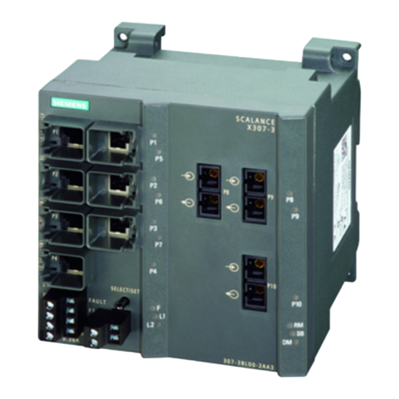
Description of the device 4.4 Product properties and device views Figure 4-3 SCALANCE X306-1LD FE Column Port number P1 *) Connection type Electrical: Fast Ethernet Electrical: Fast Ethernet *) Optical: Fast Ethernet 4.4.1.3 SCALANCE X307-3 product characteristics Possible attachments The SCALANCE X307-3 provides the following options for the connection of end devices or other network segments: ●... -
Page 52: Scalance X307-3Ld Product Characteristics
Description of the device 4.4 Product properties and device views Figure 4-4 SCALANCE X307-3 Column Port number Connection Electrical: Fast Ethernet Optical: Gigabit Ethernet type 4.4.1.4 SCALANCE X307-3LD product characteristics Possible attachments The SCALANCE X306-3LD provides the following options for the connection of end devices or other network segments: ●... -
Page 53: Scalance X308-2Lh Product Characteristics
Description of the device 4.4 Product properties and device views Figure 4-5 SCALANCE X307-3LD Column Port number Connection Electrical: Fast Ethernet Optical: Gigabit Ethernet type 4.4.1.5 SCALANCE X308-2LH product characteristics Possible attachments The SCALANCE X308-2LH provides the following options for the connection of end devices or other network segments: ●... -
Page 54: Scalance X308-2Lh+ Product Characteristics
Description of the device 4.4 Product properties and device views Figure 4-6 SCALANCE X308-2LH Column Port number Connection Electrical: Fast Ethernet Electrical: Optical: type Gigabit Ethernet Gigabit Ethernet 4.4.1.6 SCALANCE X308-2LH+ product characteristics Possible attachments The SCALANCE 308-2LH+ provides the following options for the connection of end devices or other network segments: ●... -
Page 55: Scalance X308-2 Product Characteristics
Description of the device 4.4 Product properties and device views Figure 4-7 SCALANCE X308-2LH+ Column Port number Connection Electrical: Fast Ethernet Electrical: Optical: type Gigabit Ethernet Gigabit Ethernet 4.4.1.7 SCALANCE X308-2 product characteristics Possible attachments The SCALANCE X308-2 provides the following options for the connection of end devices or other network segments: ●... -
Page 56: Scalance X308-2Ld Product Characteristics
Description of the device 4.4 Product properties and device views Figure 4-8 SCALANCE X308-2 Column Port number Connection Electrical: Fast Ethernet Electrical: Optical: type Gigabit Ethernet Gigabit Ethernet 4.4.1.8 SCALANCE X308-2LD product characteristics Possible attachments The SCALANCE X308-2LD provides the following options for the connection of end devices or other network segments: ●... -
Page 57: Scalance X310 Product Characteristics
Description of the device 4.4 Product properties and device views Figure 4-9 SCALANCE X308-2LD Column Port number Connection Electrical: Fast Ethernet Electrical: Optical: type Gigabit Ethernet Gigabit Ethernet 4.4.1.9 SCALANCE X310 product characteristics Possible attachments The SCALANCE X310 provides the following options for the connection of end devices or other network segments: ●... -
Page 58: Scalance X310Fe Product Characteristics
Description of the device 4.4 Product properties and device views Figure 4-10 SCALANCE X310 Column Port number Connection Electrical: Fast Ethernet Electrical: Gigabit Ethernet type 4.4.1.10 SCALANCE X310FE product characteristics Possible attachments The SCALANCE X310FE provides the following options for the connection of end devices or other network segments: ●... -
Page 59: Scalance X320-1Fe Product Characteristics
Description of the device 4.4 Product properties and device views Figure 4-11 SCALANCE X310FE Column Port number Connection Electrical: Fast Ethernet type 4.4.1.11 SCALANCE X320-1FE product characteristics Possible attachments The SCALANCE X320-1 FE provides the following options for the connection of end devices or other network segments: ●... -
Page 60: Scalance X320-3Ld Fe Product Characteristics
Description of the device 4.4 Product properties and device views Figure 4-12 SCALANCE X320-1 FE Column Port number Connection Electrical: Fast Ethernet Optical: type Fast Ether‐ 4.4.1.12 SCALANCE X320-3LD FE product characteristics Possible attachments The SCALANCE X320-3LD FE provides the following options for the connection of end devices or other network segments: ●... - Page 61 Description of the device 4.4 Product properties and device views Figure 4-13 SCALANCE X320-3LD FE Column Port number Connection Electrical: Fast Ethernet Optical: type Fast Ether‐ SCALANCE X-300 Operating Instructions, 11/2019, A5E01113043-24...
-
Page 62: Product Group X-300M
Description of the device 4.4 Product properties and device views 4.4.2 Product group X-300M 4.4.2.1 SCALANCE X308-2M product characteristics Possible attachments The SCALANCE X308-2M and X308-2M TS are partly modular devices and each has 8 ports. ● 4 fixed ports in the base device: 4 electrical RJ-45 jacks (with securing collars) for connection of end devices or other network segments. - Page 63 Description of the device 4.4 Product properties and device views Possible attachments (example) CAUTION Use only approved media modules in the module slots The connection of end devices or other network segments does not depend on the module slot, but rather on the selected media module. Refer to the section Media module installation in slot.
-
Page 64: Product Group Xr-300M
Description of the device 4.4 Product properties and device views Column Port number Connection type Optical: Connection type depending on module used Gigabit Ethernet 4.4.3 Product group XR-300M 4.4.3.1 SCALANCE XR324-12M product characteristics Possible attachments The SCALANCE XR324-12M is a fully modular device and has 24 ports. ●... - Page 65 Description of the device 4.4 Product properties and device views Example of a configuration CAUTION Use only approved media modules in the module slots The connection of end devices or other network segments does not depend on the module slot, but rather on the selected media module. Refer to the section Media module installation in slot.
-
Page 66: X-300Eec Product Group
Description of the device 4.4 Product properties and device views 4.4.4 X-300EEC product group 4.4.4.1 SCALANCE X-300EEC product characteristics Variants The SCALANCE X‑300EEC is a 19"/2 device with 9 ports for the connection of end devices or other network segments. There are 2 device types with the following ports: ●... - Page 67 Description of the device 4.4 Product properties and device views Figure 4-18 SCALANCE X302‑7EEC (from below) with protective bracket and LC connector Replacing the C‑PLUG In the X‑300EEC devices, the slot for the C-PLUG is on the top on the housing. Figure 4-19 C-PLUG of the X‑300EEC NOTICE...
- Page 68 Description of the device 4.4 Product properties and device views Terminal block for signaling contact and power supply The terminal block of the X‑300EEC for connecting the signaling contact and power supply has the following terminals: ● F1, F2: Signaling contact The 2 signaling contacts on the device version with a redundant power supply are energized in parallel.
- Page 69 Description of the device 4.4 Product properties and device views Ports of the X302-7EEC The SCALANCE X302-7EEC has the following ports: ● 2 electrical gigabit ports (P8 to P9) ● 7 optical Fast Ethernet ports (P1 to P7) Figure 4-20 SCALANCE X302-7EEC Port number Connection type...
- Page 70 Description of the device 4.4 Product properties and device views Ports of the X307-2EEC The SCALANCE X307-2EEC has the following ports: ● 7 electrical ports (P3 to P9) – 5 Fast Ethernet ports (P3 to P7) – 2 gigabit ports (P8, P9) ●...
-
Page 71: Xr-300M Eec Product Group
CAUTION Use only approved media modules If you use media modules that are not approved by Siemens AG, there is no guarantee that the device will function according to the specification. If you use unapproved media modules, this can lead to the following problems: ●... -
Page 72: Product Group X-300M Poe
Description of the device 4.4 Product properties and device views 4.4.6 Product group X-300M PoE 4.4.6.1 SCALANCE X308-2M PoE product characteristics Possible attachments The SCALANCE X308-2M PoE is a partially modular device and has eight ports. ● Four fixed ports in the base device: Four PoE-compliant ports (RJ-45 jacks with securing collars) for connection of end devices or other network segments. - Page 73 Description of the device 4.4 Product properties and device views Possible attachments (example) CAUTION Use only approved media modules in the module slots The connection of end devices or other network segments does not depend on the module slot, but rather on the selected media module. Refer to the section Media module installation in slot.
-
Page 74: Product Group Xr-300M Poe
Description of the device 4.4 Product properties and device views Column Port number P1 (gigabit Ethernet) P5 (gigabit multimode fiber- optic cable, SC ports) (interface depends on SFP P2 (gigabit Ethernet) used) P3 (gigabit Ethernet) P6 (gigabit multimode fiber- P8(interface depends on SFP optic cable, SC ports) used) P4 (gigabit Ethernet) -
Page 75: Mm900 Media Modules
Description of the device 4.4 Product properties and device views CAUTION Use only approved modules in the slots Possible module connection types: ● 2 x RJ-45 ● 2 x FX100 ● 2 x FX1000 ● or 2 x SFP slots With FX, single mode fibers or multimode fibers are possible. -
Page 76: Mm991-2Fm (Bfoc) Product Characteristics
Description of the device 4.4 Product properties and device views 4.4.8.2 MM991-2FM (BFOC) product characteristics Possible attachments The MM991-2FM (BFOC) media module has the following: ● 2 x 100 Mbps, BFOC port optical (multimode, glass) with diagnostics up to max. 5 km Figure 4-27 MM991-2FM (BFOC) [9912AB] [Device labeling in square brackets]... -
Page 77: Mm991-2 (Sc) Product Characteristics
Description of the device 4.4 Product properties and device views 4.4.8.4 MM991-2 (SC) product characteristics Possible attachments The MM991-2 (SC) media module has the following: ● 2 x 100 Mbps, SC port optical, (multimode glass), up to max. 5 km Figure 4-29 MM991-2 (SC) [9912AD] [Device labeling in square brackets]... -
Page 78: Mm991-2Lh+ (Sc) Product Characteristics
Description of the device 4.4 Product properties and device views 4.4.8.6 MM991-2LH+ (SC) product characteristics Possible attachments The MM991-2LH+ (SC) media module has the following: ● 2 x 100 Mbps, SC port optical, (single mode glass), up to max. 70 km Figure 4-31 MM991-2LH+ (SC) [9912AE] [Device labeling in square brackets]... -
Page 79: Mm992-2Cu Product Characteristics
Description of the device 4.4 Product properties and device views [Device labeling in square brackets] Note Installation of the XR-300M, XR-300M PoE and XR-300M EEC Only the lower slots may be equipped with the MM991-2P. ● XR-300M: Maximum 6 modules in slots 7 to 12 ●... -
Page 80: Mm992-2Cuc Product Characteristics
Description of the device 4.4 Product properties and device views 4.4.8.9 MM992-2CUC product characteristics Possible attachments The MM992-2CUC media module has the following: ● 2 x 10/100/1000 Mbps, RJ-45 ports electrical with securing collar Figure 4-34 MM992-2CUC [9922GA] [Device labeling in square brackets] Note For connection to electrical networks note the information in Appendix A.1 and A.2. - Page 81 Description of the device 4.4 Product properties and device views [Device labeling in square brackets] NOTICE Cable connection between VD devices Use the same type of cable for the cable connection between two VD devices. Infrastructure cables as well as any patch cables in use must be of the same cable type. If the cable type between the two VD devices changes during the transmission path, signal reflections can occur at the connection site of the different cables, which can result in frame losses.
-
Page 82: Mm992-2 (Sc) Product Characteristics
Description of the device 4.4 Product properties and device views 4.4.8.11 MM992-2 (SC) product characteristics Possible attachments The MM992-2 (SC) media module has the following: ● 2 x 1000 Mbps, SC port optical, (multimode glass), up to max. 750 m Figure 4-36 MM992-2 (SC) [9922AL] [Device labeling in square brackets]... -
Page 83: Mm992-2Lh (Sc) Product Characteristics
Description of the device 4.4 Product properties and device views 4.4.8.13 MM992-2LH (SC) product characteristics Possible attachments The MM992-2LH (SC) media module has the following: ● 2 x 1000 Mbps, SC port optical, (single mode glass), up to max. 40 km Figure 4-38 MM992-2LH (SC) [9922AN] [Device labeling in square brackets]... -
Page 84: Mm992-2Elh (Sc) Product Characteristics
Description of the device 4.4 Product properties and device views 4.4.8.15 MM992-2ELH (SC) product characteristics Possible attachments The MM992-2ELH (SC) media module has the following: ● 2 x 1000 Mbps, SC port optical, (single mode glass), up to max. 120 km Figure 4-40 MM992-2ELH (SC) [9922AQ] [Device labeling in square brackets]... -
Page 85: General Notes On Mm900
Description of the device 4.4 Product properties and device views Possible attachments The media modules MM992-2SFP / M992-2SFP (C) have: ● 2 x 100/1000 Mbps, SFP slot Figure 4-42 MM992-2SFP [9922AS] [Device labeling in square brackets] 4.4.8.18 General notes on MM900 Note Use media modules only in an approved modular device ("M") Use an MM900 media module only in a device equipped with suitable slots for such modules. -
Page 86: Sfp Transceiver
Description of the device 4.4 Product properties and device views Possible attachment Figure Electrical RJ-45 ports without securing collar Electrical RJ-45 ports with securing collar GE M12 connector electrical SFP transceivers Only the SFP media module MM992-2SFP may be fitted with approved SFP transceivers. The SFP me‐ dia module can be fitted with up to two SFPs. -
Page 87: Mm992-2Sfp / Mm992-2Sfp (C) Product Properties
Description of the device 4.4 Product properties and device views Type Properties Article number SFP991-1LH+ * 1 x 100 Mbps LC port optical for glass FO cable 6GK5 991-1AE00-8AA0 (single mode) up to max. 70 km SFP991-1ELH200 * 1 x 100 Mbps LC port optical for glass FO cable 6GK5 991-1AE30-8AA0 (single mode) up to max. -
Page 88: Interfaces And Signaling Contact Of The Switches
Description of the device 4.5 Interfaces and signaling contact of the switches Interfaces and signaling contact of the switches 4.5.1 Ethernet interfaces - electrical ports 4.5.1.1 10Base-T / 100Base-TX Transmission rate The transmission rate of the electrical ports is 10 Mbps or as Fast Ethernet ports 100 Mbps. Transmission mode The transmission mode for 10Base-T / 100Base-TX is specified in the IEEE 802.3i / IEEE 802.3u standards of the Institute of Electrical and Electronic Engineers. -
Page 89: 1000Base-T
Description of the device 4.5 Interfaces and signaling contact of the switches Connectors A node or network segment is connected to an 8-pin RJ-45 jack with securing collar. Due to its flush fitting with an IE FC RJ-45 Plug 180 / IE FC RJ45 Plug 145 connector, the securing collar ensures a robust connection suitable for industry that provides tensile and bending strain relief for the inserted connector. -
Page 90: Power Over Ethernet (Poe)
Description of the device 4.5 Interfaces and signaling contact of the switches Transmission medium Data is transmitted over an eight-wire twisted pair cable. Note For data transmission at 1 Gbps, at least a Cat 5e twisted-pair cable with 4 x 2 wires is necessary. -
Page 91: Ports Of The X308-2M Poe
Description of the device 4.5 Interfaces and signaling contact of the switches 4.5.1.4 Ports of the X308-2M PoE PoE ports of SCALANCE X‑300M PoE switches As a PSE, the PoE switch supplies PoE-capable devices with power over Ethernet. The 48 V power required to supply the powered devices is generated internally on the switch, no extra power supply unit is necessary. -
Page 92: Isolation Between The Tp Ports
Description of the device 4.5 Interfaces and signaling contact of the switches 4.5.1.6 Isolation between the TP ports All ports meet the requirement of 1.5 kV isolation voltage to the shield and between the ports (corresponds to IEEE802.3, Environment B). Note Exceptions are X307-3, X307-3LD, X308-2, X308-2LD, X308-2LH, X308-2LH+, X310, X310FE The following port group is an exception to this:... -
Page 93: 1000Base-Lx / 100Base-Fx
Description of the device 4.5 Interfaces and signaling contact of the switches 4.5.2.2 1000Base-LX / 100Base-FX Transmission rate The transmission rate of the optical gigabit ports is 1 Gbps. Transmission mode Transmission with 1000Base-LX is defined in the IEEE 802.3z standard and is specified as 1000 Mbps transmission rate and full duplex. -
Page 94: C-Plug (Configuration Plug)
Description of the device 4.6 C-PLUG (configuration plug) Error indication ● The signaling by the signaling contact is synchronized with the fault LED, in other words, all errors displayed by this LED (freely configurable) are also signaled on the signaling contact. ●... - Page 95 Description of the device 4.6 C-PLUG (configuration plug) Diagnostics Inserting a C-PLUG that does not contain the configuration of a compatible device type, accidentally removing the C-PLUG or general malfunctions of the C-PLUG are signaled by the diagnostics mechanisms of the IE Switch (LEDs, WEB-based management, SNMP, CLI and PROFINET diagnostics).
-
Page 96: Starting The Device For The First Time
Description of the device 4.7 Starting the device for the first time The C‑PLUG can be removed from the slot using flat pliers, tweezers, or a small screwdriver. Product group Slot Figure X-300 Rear of the device 1. Remove the screw cover. X-300M 2. -
Page 97: Installation
Installation Safety notices for installation Safety notices When installing the device, keep to the safety notices listed below. WARNING If a device is operated in an ambient temperature of more than 50 °C, the temperature of the device housing may be higher than 70 °C. The device must therefore be installed so that it is only accessible to service personnel or users that are aware of the reason for restricted access and the required safety measures at an ambient temperature higher than 50 °C. -
Page 98: Pollution Degree (Only 2)
Installation 5.2 Pollution degree (only 2) Pollution degree (only 2) WARNING The device may only be operated in an environment of pollution degree class 2 (cf. IEC 60664-1). WARNING The device is intended for indoor use only. WARNING When used in hazardous environments corresponding to Class I, Division 2 or Class I, Zone 2, the device must be installed in a cabinet or a suitable enclosure. - Page 99 Installation 5.2 Pollution degree (only 2) To fulfill requirements for safe operation with regard to mechanical stability, flame retardation, stability, and protection against contact, the following alternative types of installation are specified: ● Installation in a suitable cabinet ● Installation in a suitable enclosure ●...
-
Page 100: Overview Of The Methods Of Installation
Installation 5.3 Overview of the methods of installation Minimum clearances If you install the IE Switch X-300EEC in enclosures without forced ventilation or cooling, minimum clearances must be maintained to neighboring devices or the wall of the enclosure. By keeping to the minimum clearances, there is then an adequate stream of air for heat dissipation during operation. -
Page 101: Installing A Switch
Installation 5.4 Installing a switch Installing a switch CAUTION Electrical connections Make sure that the power supply of the switch is turned off when fitting the connectors for the power supply and the signaling contacts. For information on the electrical connections, refer to Section Connecting (Page 119). 5.4.1 Installation on a DIN rail WARNING... - Page 102 Installation 5.4 Installing a switch 4. Fit the connectors for the signaling contact. 5. Insert the terminal blocks into the sockets on the IE Switch X-300. Figure 5-1 Mounting an IE Switch X-300 on a DIN rail (35 mm) Uninstalling To remove an IE Switch X‑300 from the DIN rail: 1.
-
Page 103: Installation On A Standard Rail
Installation 5.4 Installing a switch 5.4.2 Installation on a standard rail Installation on a SIMATIC S7-300 standard rail 1. Hang the upper guide at the top of the switch housing onto the S7 standard rail. 2. Screw the IE Switch X‑300 to the underside of the standard rail. 3. -
Page 104: Wall Mounting
Installation 5.4 Installing a switch Uninstalling To remove an IE Switch X‑300 from the SIMATIC S7-300 standard rail, follow these steps: 1. Disconnect all connected cables. 2. Loosen the screws on the underside of the standard rail and lift the IE Switch X-300 away from the rail. -
Page 105: 19" Rack Mounting
Installation 5.4 Installing a switch Note Wall mounting of a rack device For wall mounting of a rack device (R), use suitable fittings such as a mounting bracket. Wall mounting of the IE Switch X‑300EEC To mount the IE Switch X‑300EEC on a wall, you require an additional securing bracket. You will find the dimensions for a suitable securing bracket in section Graphics (Page 221). - Page 106 Installation 5.4 Installing a switch Minimum clearances If you install the IE Switch in rack devices without forced ventilation or cooling, minimum clearances must be maintained to neighboring devices or the wall of the enclosure. By keeping to the minimum clearances, there is then an adequate stream of air for heat dissipation during operation.
- Page 107 Installation 5.4 Installing a switch 19" rack mounting with normal orientation 19" rack mounting Select the required rack device (R) and the 19" cabinet. Fix the two mounting brackets with 4 screws each to the sides of the housing. The maximum tightening torque for these screws is 0.5 Nm.
- Page 108 Installation 5.4 Installing a switch Desktop operation (only 24 V DC variants with adhesive feet) CAUTION No desktop operation for devices with 100 to 240 V AC power supply Desktop operation is permitted only for the 24 VDC variants of the rack devices (R). The adhesive feet ship with the 24 VDC variants.
-
Page 109: 19" Rack Mounting - X-300Eec Product Group
Installation 5.4 Installing a switch 5.4.5 19" rack mounting - X-300EEC product group The X-300EEC can be installed in a rack singly or as pairs. ● Mounting singly: To do this, an X-300EEC device is secured to a plate and screwed into the 19" rack. ●... -
Page 110: 19" Rack Mounting - Xr-300M Eec Product Group
Installation 5.4 Installing a switch 5.4.6 19" rack mounting - XR-300M EEC product group CAUTION Danger of injury by falling objects If you do not use the supplied mounting brackets for 19"rack installation, it is not possible to install the device correctly. Use only the supplied mounting brackets. - Page 111 Installation 5.4 Installing a switch NOTICE Four-point mounting If mechanical load is high, the device should be secured at four points. You will find more detailed information in the section "Mechanical stability in operation". Normal orientation Normal orientation of the device ●...
- Page 112 Installation 5.4 Installing a switch 19" rack mounting CAUTION: If you install a rack device with components inserted. The locking mechanisms of components installed in the rack device (for example the handles of media modules or the clips on the SFP) must be closed. See also installation of modular devices: - Installing media modules in a slot - Installing an SFP in an SFP media module.
-
Page 113: Inserting Media Modules And Sfp Transceivers
Installation 5.5 Inserting media modules and SFP transceivers Inserting media modules and SFP transceivers 5.5.1 Installation and removal of media modules Connecting media modules and SFP transceivers WARNING Install and remove media modules only when the power is off Media modules may only be inserted in or removed from a SCALANCE device when the power supply to the device has been turned off. - Page 114 Remove the protective caps only immediately before you use the plug-in connection. NOTICE Use only approved SFPs If you use components not approved by Siemens AG, in particular SFPs, Siemens cannot accept any responsibility for the correct functioning of the "Ethernet switch system" according to the specification.
- Page 115 Installation 5.5 Inserting media modules and SFP transceivers Note Slot number With modular devices, the MM900 media modules must be given a slot number. The slot number labels are supplied with the modular devices. Installing a media module The media module is inserted with the handle pulled out. When the handle is inserted, the media module is locked in the device.
- Page 116 Installation 5.5 Inserting media modules and SFP transceivers Place the media module in the guide rails of the device slot. The media module is correctly installed when it clips easi‐ ly into the device. Push the handle back into the media module. This locks the media module in the device.
-
Page 117: Sfp Installation In Sfp Media Module
NOTICE Use only approved SFPs If you use SFPs that are not approved by Siemens AG, there is no guarantee that the device will function according to the specification. If you use unapproved SFPs, this can lead to the following problems: ●... - Page 118 Installation 5.5 Inserting media modules and SFP transceivers Select the required SFP media module in the slot of the device. (Example: X-308-2M, slot 2) Insert the SFP with the clip closed in the SFP media module. Notice: Closing the clip after insertion does not lock the device in the rack.
-
Page 119: Connecting
Connecting Safety when connecting up Safety notices When connecting up the device, keep to the safety notices listed below. Safety note on devices with 24 V DC power supply WARNING Safety extra low voltage (only devices with 24 V DC power supply) The equipment is designed for operation with Safety Extra-Low Voltage (SELV) by a Limited Power Source (LPS). - Page 120 Connecting 6.1 Safety when connecting up Safety note on devices with 100 to 240 V AC power supply WARNING Danger from line voltage The supply voltage for the devices listed is 100 to 240 V AC. This device can only function correctly and safely if it is transported, stored, set up, and installed correctly, and operated and maintained as recommended.
- Page 121 Connecting 6.1 Safety when connecting up Safety notices for use according to ATEX and IECEx If you use the device under ATEX or IECEx conditions you must also keep to the following safety notices in addition to the general safety notices for protection against explosion: WARNING Take measures to prevent transient voltage surges of more than 40% of the rated voltage.
-
Page 122: Wiring Rules
Connecting 6.2 Wiring rules Note Commissioning devices with redundancy mechanisms If you use redundancy mechanisms ("HRP" media redundancy or "MRP" and/or redundant coupling of rings over standby coupling), open the redundant path before you insert a new or replacement device in an operational network. A bad configuration or attachment of the Ethernet cables to incorrectly configured ports causes overload in the network and a breakdown in communication. -
Page 123: Connecting The Switch
Connecting 6.5 Grounding Note Wire end ferrules Use crimp shapes with smooth surfaces, such as provided by square and trapeze shaped crimp cross sections. Crimp shapes with wave-shaped profile are unsuitable. Connecting the switch Procedure for connecting the device Follow the steps below to connect the device: 1. -
Page 124: Scalance X-300Eec And Rack Devices
Connecting 6.5 Grounding S7 standard rail The device is grounded over its rear panel and the neck of the screw. Wall mounting The device is grounded by the securing screw in the unpainted hole. Please note that IE Switches X-300 must be grounded over one securing screw with minimum resistance. -
Page 125: Grounding Of The Rack Devices
Connecting 6.5 Grounding Protective ground When the device is operated with multirange power supply unit 100 to 240 VAC / 60 to 250 VDC, the protective ground is connected in addition to the functional ground. CAUTION Danger from line voltage Grounding simply via the housing is inadequate. -
Page 126: Grounding Of The X-300Eec
Connecting 6.5 Grounding Connecting up functional ground Screw-in grounding bolts Pressed in grounding bolts ③ Grounding terminal with cable ④ Washer ⑤ Spring washer ⑥ Follow the steps below to connect the functional ground: ③ ④ ⑤ 1. Put the parts together on the grounding bolt as shown in the drawing. - Page 127 Connecting 6.5 Grounding Connecting ground ① Grounding terminal with cable ② Washer ③ Spring washer ④ Follow the steps below to connect ground: ① ② ③ 1. Put the parts together on the grounding bolt as shown in the drawing. ④...
-
Page 128: Power Supply
Connecting 6.6 Power supply Power supply 6.6.1 24 VDC power supply 6.6.1.1 Safety extra low voltage 24 V safety extra-low voltage (SELV) WARNING Operation only with safety-extra low voltage ● The IE Switch X-300 is designed for operation with safety extra-low voltage (SELV). This means that only safety extra-low voltages (SELV) complying with IEC950/EN60950/ VDE0805 can be connected to the power supply terminals. -
Page 129: X-300 Product Group
Connecting 6.6 Power supply Note Device variants There are devices with one power supply unit or with two power supply units. Depending on the variant, the data cable outlet can be on the front or at the rear of the device. Connecting 24 V safety extra-low voltage (SELV) ●... -
Page 130: X-300M Product Group
Connecting 6.6 Power supply Device Device version 24 V safety extra-low voltage (SELV) (power supply) can be connected redundantly X308-2LH 1 x 24 VDC ● X308-2LH+ 1 x 24 VDC ● X310 1 x 24 VDC ● X310FE 1 x 24 VDC ●... -
Page 131: X-300M Poe Product Group
Connecting 6.6 Power supply Table 6-6 24 to 48 V DC safety extra low voltage Device Device version 24 V safety extra-low voltage (power supply) (SELV) can be connected redundantly XR324-4M EEC 1 x 24 to 48 V DC ● 2 x 24 to 48 V DC ●... - Page 132 Connecting 6.6 Power supply Connecting a redundant power supply to 1 power supply unit Use the terminal block "X1" to connect the power supply. M2 L2 Figure 6-2 Assignment of the LED display to the pins for redundant power supply with devices with one power supply unit M2 L2 M2 L2...
-
Page 133: Connecting A Redundant Power Supply To The Xr300-Eec
Connecting 6.6 Power supply L1 L2 L1 M1 L1 M1 Figure 6-4 Assignment of the LED display to the pins for redundant power supply with devices with two power supply units ● If the power supply fails at pins L1/M1 of terminal block "X1", this is indicated by LED L1. ●... - Page 134 Connecting 6.6 Power supply L1 L2 L1 L2 L1 M1 L1 M1 L1 M1 L1 M1 Figure 6-6 Assignment of the LED display to the pins for redundant power supply with devices with two power supply units ● If the power supply fails at pins L1/M1, this is indicated by LED L1. ●...
-
Page 135: 100 To 240 Vac Power Supply
Connecting 6.6 Power supply 6.6.2 100 to 240 VAC power supply WARNING Danger to life from line voltage for devices with a 240 V AC supply voltage This device can only function correctly and safely if it is transported, stored, set up, and installed correctly, and operated and maintained as recommended. -
Page 136: Xr-300M Eec Product Group
Connecting 6.6 Power supply 6.6.2.3 XR-300M EEC product group Table 6-11 100 to 240 V AC voltage Device Device version (power supply) 100 to 240 V voltage Redundant Single XR324-4M EEC 1 x 100 to 240 V AC / 60 to 250 V DC ●... - Page 137 Connecting 6.6 Power supply Procedure Follow the steps below to fit the connector to a two-wire cable: 1. Connect the cable to the terminal block. Strip the cable jacket only as far as necessary to be able to strip the insulation and connect up the wires. 2.
-
Page 138: Connecting The 100 To 240 Vac Power Supply
Connecting 6.6 Power supply 6.6.2.6 Connecting the 100 to 240 VAC power supply Connecting the 100 to 240 VAC power supply via the 2-pin terminal block There are devices with single (1 x 100 to 240 V) or redundant power supply (2 x 100 to 240 V). The cable outlet can be to the front or rear depending on the device type. - Page 139 Connecting 6.6 Power supply Grounding WARNING Danger from line voltage Grounding simply via the housing is inadequate. In this case, connect the functional ground to ensure reliable operation. With devices with a supply voltage of 100 to 240 VAC / 60 to 250 VDC, you should also connect the protective earth to the grounding bolt.
-
Page 140: Connecting The 100 To 240 V Ac Power Supply With The Xr-300M Poe
Connecting 6.7 Signaling contact 6.6.2.8 Connecting the 100 to 240 V AC power supply with the XR-300M PoE Connecting to the power supply The devices have a single power supply (1 x 100 to 240 V). The power supply is connected using a 2-pin plug-in terminal block. Terminal block assignment (2-pin) Table 6-15 Pin assignment of the 100 to 240 VAC power supply... -
Page 141: Signaling Contact 100 To 240 Vac / 60 To 250 Vdc (X-300Eec)
Connecting 6.7 Signaling contact The signaling contact can be subjected to a maximum load of 100 mA (safety extra low voltage SELV 12 VDC / 24 VDC). Table 6-16 Pin assignment of the signaling contact Pin number Assignment (example) Pin 1 Pin 2 NOTICE Laying the connecting cables of the signaling contact with the X‑300EEC... - Page 142 Connecting 6.7 Signaling contact Signaling contact 100 to 240 VAC / 60 to 250 VDC The signaling contact is connected to a 3-pin plug-in terminal block. Table 6-17 Pin assignment of the 100 to 240 VAC / 60 to 250 VDC signaling contact Pin number Assignment NC contact...
-
Page 143: Configuration, Displays And Display Elements
Configuration, displays and display elements Assignment of slot numbers CAUTION Specifying the slot number Slots should be numbered in ascending order. Insert a label with the slot number in the slot on the housing starting, for example, with the fixed ports and continuing with the modular ports (with MM900 media modules fitted). -
Page 144: Show Location
Configuration, displays and display elements 7.3 XR-300 diagnostics port Show Location Localizing an IE Switches X-300 To identify an IE Switch X-300 locally and with certainty, you can use the "show location" function on a programming device to select the node over the network and make it flash. This can be used, for example, when assigning addresses to make sure that the correct node receives the address. -
Page 145: The Set / Select Button
Configuration, displays and display elements 7.4 The SET / SELECT button Pin assignment The following table shows the pin assignment of the RJ-11 plug and the D sub female connector: Figure 7-2 RJ-11 jack (schematic) RJ-11 plug D-sub 9-pin, female Assignment Assignment n. - Page 146 Configuration, displays and display elements 7.4 The SET / SELECT button Resetting the device to the factory defaults If you reset, all the changes you have made will be overwritten by factory defaults. Follow the steps outlined below: 1. Turn on display mode A. Display mode A is active when the "DM" LED is not lit. If this LED is lit or flashing, you will need to press the SET/SELECT briefly (possibly several times) until the "DM"...
-
Page 147: Led Display
Configuration, displays and display elements 7.5 LED display LED display The "RM" LED for the "redundancy manager" function The "RM" LED indicates whether or not the device is operating in the role of redundancy manager and whether or not the ring is operating error-free. LED color LED status Meaning... - Page 148 Configuration, displays and display elements 7.5 LED display The "DM" LED for the display mode The "DM" LED (Display Mode) indicates which of the four display modes A, B, C or D is currently active. The meaning of the L1, L2 and P1, P2, ... LEDs depends on the display mode. LED color LED status Meaning...
- Page 149 Configuration, displays and display elements 7.5 LED display Meaning in display mode D Color Status Meaning L1 / L2 Power supply L1 / L2 is not monitored. If L1 / L2 falls below 17 , the signaling contact does not respond. green Power supply L1 / L2 is monitored.
- Page 150 Configuration, displays and display elements 7.5 LED display Meaning in display mode B LED color LED status Meaning Port operating at 10 Mbps. green Port operating at 100 Mbps. orange Port operating at 1000 Mbps. If there is a problem on the connection and the type of transmission is fixed (autonegotiation off), the desired status, in other words the set transmission speed (1000 Mbps, 100 Mbps, 10 Mbps) continues to be displayed.
-
Page 151: Technical Specifications
Technical specifications Overview of operating temperatures for SCALANCE X-300 Operating temperature depending on the media modules used The information applies to media modules with product version 2 (PV2): Type Installation Without media MM992-2CUC MM991-2LH+ (SC) Media module Media module location module MM992-2CU MM992-2LH... -
Page 152: X-300 Technical Specifications
Technical specifications 8.2 X-300 technical specifications Type Installation Without media MM992-2CUC MM991-2LH+ (SC) Media module Media module location module MM992-2CU MM992-2LH MM992-2SFP MM992-2SFP MM991-2 MM992-2LH+ with SFP trans‐ with SFP trans‐ MM991-2LD MM992-2ELH ceiver ceiver MM991-2 (SC) SFP991-1 SFP991-1LH+ MM991-2LD (SC) SFP991-1LD SFP992-1LH MM992-2... -
Page 153: Construction, Installation And Environmental Conditions
Technical specifications 8.2 X-300 technical specifications 8.2.1 Construction, installation and environmental conditions Table 8-1 Construction Device variant Dimensions (W x H x D) Weight Degree of protection X304-2FE, 60 × 125 × 123 mm 700 g IP30 X306-1LD FE X307-3, 120 ×... -
Page 154: Connectors And Electrical Data
Technical specifications 8.2 X-300 technical specifications Table 8-3 Permitted ambient conditions Device variant Storage/transport tem‐ Operating temperature Max. relative humid‐ Max. ambient tempera‐ perature ity in operation at 25 ture at operating altitude °C X304-2FE, -40 °C to +70 °C As of hardware product <= 95% (no conden‐... - Page 155 Technical specifications 8.2 X-300 technical specifications Device variant Electrical Optical over twisted pair over fiber-optic cable X308-2LD 7 x RJ‑45 jacks with MDI‑X assignment 2 x SC duplex sockets 10/100 Mbps (half / full duplex) (1000 Mbps, full duplex to 1000BaseLX) 1 x RJ‑45 jacks with MDI‑X assignment 10/100/1000 Mbps (half / full duplex)
- Page 156 Technical specifications 8.2 X-300 technical specifications Device variant Power loss at Current consumption at Overcurrent protection 24 VDC rated voltage 24 VDC at input (non-replacea‐ ble fuse) X307-3, 9.6 W 400 mA 3 A / 32 V X307-3LD, X308-2, X308-2LD, X308-2LH, X308-2LH+, X310,...
-
Page 157: Cable Lengths
Technical specifications 8.2 X-300 technical specifications Device variant Transmitter output (optical) Receiver input min. [dBm] max. [dBm] Sensitivity min. [dBm] Input power max. [dBm] X320-3LD FE Fast Ethernet, long distance interface Fast Ethernet, multimode interface Note Exception in the naming of X320-3LD FE With the X320-3LD FE IE switch, the key to the name is different. - Page 158 Technical specifications 8.2 X-300 technical specifications Table 8-11 Permitted cable lengths (copper cable - gigabit Ethernet) Cable type Accessory (plug, outlet, TP cord) Permitted cable length IE FC standard cable, 4×2, 24 with IE FC RJ-45 Plug 180, 0 to 90 m IE FC flexible cable, 4×2, 24 IE FC standard cable, 4×2, 22 with IE FC Outlet RJ-45...
-
Page 159: Other Properties
Technical specifications 8.2 X-300 technical specifications Device variant Fiber-optic cable type Permitted cable length Attenuation X308-2LH 9/125 µm to 40 km ≤0.4 dB/km at 1550 nm; maximum insertion loss single mode fiber 0.5 dB; 18 dB max. permitted FO cable attenuation at 2 dB link power margin;... - Page 160 Technical specifications 8.2 X-300 technical specifications Note The IE Switches X-300 support "full wire speed switching" complying with IEEE 802.3 on all ports. The number of packets therefore depends on the packet length. Full wire speed switching Number of frames per second At a frame length of At 100 Mbps At 1000 Mbps...
-
Page 161: X-300M Technical Specifications
Technical specifications 8.3 X-300M technical specifications Note For a device to be used in PRP networks, it must be able to process a frame length of at least 1528 bytes (Jumbo Frames). This value is the maximum frame length including VLAN tag of 1522 bytes plus the length of the PRP trailer of 6 bytes. -
Page 162: Connectors And Electrical Data
Technical specifications 8.3 X-300M technical specifications Table 8-17 Operating temperature depending on the media modules used Media module Installation di‐ Operating temperature rection Without media module Horizontal -40 °C to +70 ℃ Vertical -40 °C to +50 ℃ MM992-2CUC Horizontal -40 °C to +70 ℃... - Page 163 Technical specifications 8.3 X-300M technical specifications Media module slots 4 x modular (2 ports per slot) Transmitter output (optical) and receiver input The values correspond to those of the permitted MM900 media modules and SFP transceivers. Table 8-19 Electrical data: Power supply Device version Redundant Redundant...
-
Page 164: Cable Lengths
Technical specifications 8.3 X-300M technical specifications Table 8-23 Plug-in terminal block for connectors of the power supply and signaling contact Device version Power supply Signaling contact (power supply) 12 VDC 1 x 4-pin 1 x 2-pin 24 VDC 1 x 4-pin 1 x 2-pin 8.3.3 Cable lengths... -
Page 165: Other Properties
Technical specifications 8.3 X-300M technical specifications 8.3.4 Other properties Switching properties Max. number of learnable addresses 8000 Aging time 30 sec Switching technique Store and forward Latency 5 μs Reconfiguration times for redundancy mechanisms Redundancy mechanism Reconfiguration times 300 ms Standby link 300 ms 200 ms... -
Page 166: Xr-300M Technical Specifications
Technical specifications 8.4 XR-300M technical specifications Note The following applies to IE Switches X-300: The number of IE Switches X-300 connected in a line influences the frame delay time. When a frame passes through the switch, this is delayed by the Store&Forward function of the IE Switch X-300 by the following values: ●... - Page 167 Technical specifications 8.4 XR-300M technical specifications Table 8-27 Installation options Device version Installation options (power supply) 2 x 24 VDC ● 19" rack ● Desktop operation with adhesive feet 1 x 100 to 240 VAC 19" rack Note: If mechanical load is high, the device should be secured at four points. You will find more detailed information in the section "Mechanical load in operation".
-
Page 168: Connectors And Electrical Data
Technical specifications 8.4 XR-300M technical specifications Media module Installation di‐ Operating temperature rection MM991-2LH+ (SC) Horizontal Maximum 2 modules in slots 11 and 12: MM992-2LH -40 °C to +60 °C MM992-2LH+ With more than 2 modules or other slot assign‐ MM992-2ELH ment: -40 °C to +50 °C... - Page 169 Technical specifications 8.4 XR-300M technical specifications Table 8-31 Electrical data: Power supply Device version Redundant Redundant Power supply (power supply) power sup‐ power supply ply unit possible 2 x 24 VDC Rated voltage 24 VDC Voltage range 19.2 VDC - 28.8 Permitted voltage range 18.5 VDC - 30.2 incl.
-
Page 170: Cable Lengths
Technical specifications 8.4 XR-300M technical specifications 8.4.3 Cable lengths Table 8-36 Permitted cable lengths (copper cable - Fast Ethernet) Cable type Accessory (plug, outlet, TP cord) Permitted cable length IE TP torsion cable with IE FC Outlet RJ-45 0 to 45 m + 10 m TP cord + 10 m TP cord with IE FC RJ-45 Plug 180... -
Page 171: Block Architecture
Technical specifications 8.4 XR-300M technical specifications 8.4.4 Block architecture Block architecture with SCALANCE XR‑300 devices The XR324-12M and XR324-4M handle the Ethernet frame traffic of the 24 ports with the aid of three switch blocks. ● The three switch blocks are connected in series (block 1 via block 2 to block 3) ●... -
Page 172: Other Properties
Technical specifications 8.4 XR-300M technical specifications 8.4.5 Other properties Switching properties Max. number of learnable addresses 8000 Aging time 30 sec Switching technique Store and forward Latency 5 μs Reconfiguration times for redundancy mechanisms Redundancy mechanism Reconfiguration times 300 ms Standby link 300 ms 200 ms... -
Page 173: Technical Specifications For X-300Eec
Technical specifications 8.5 Technical specifications for X-300EEC Note The following applies to IE Switches X-300: The number of IE Switches X-300 connected in a line influences the frame delay time. When a frame passes through the switch, this is delayed by the Store&Forward function of the IE Switch X-300 by the following values: ●... -
Page 174: Construction, Installation And Environmental Conditions
Technical specifications 8.5 Technical specifications for X-300EEC 8.5.1 Construction, installation and environmental conditions Table 8-38 Construction Device version Dimensions (W x H x D) Weight Degree of protec‐ tion (power supply) 1 24 VDC power supply unit ● Without clip: 1800 g IP30 60 ×... - Page 175 Technical specifications 8.5 Technical specifications for X-300EEC Table 8-41 Mechanical stability Strain withstood / category (standard) Test conditions Vibration Frequency range 10 Hz to 150 Hz: (IEC 60068-2-6) ● Transit frequency: 58 Hz to 60 Hz ● Peak value of the displacement [mm] below the transit frequency: 0.075 ●...
-
Page 176: Connectors And Electrical Data
Technical specifications 8.5 Technical specifications for X-300EEC 8.5.2 Connectors and electrical data Table 8-42 Connection for end devices or network components Device variant Electrical Optical over twisted pair over fiber-optic cable X302-7EEC 2 x RJ‑45 jacks with MDI‑X assignment 7 x LC sockets multimode (all variants) 10/100/1000 Mbps (half / full duplex) (100 Mbps, full duplex) - Page 177 Technical specifications 8.5 Technical specifications for X-300EEC Table 8-45 Electrical data: Overcurrent protection Device version Overcurrent protection of the power supply Non-replaceable fuse (power supply) 1 power supply unit 24 to 48 VDC 1 x T4A / 125 V 2 power supply units 24 to 48 VDC 2 x T4A / 125 V 1 x power supply unit 100 to 240 VAC / 1 x T4A / 250 V (AC)
-
Page 178: Cable Lengths
Technical specifications 8.5 Technical specifications for X-300EEC Table 8-49 Overvoltage category General Overvoltage category II In the application range of EN 60255-27 Overvoltage category III 8.5.3 Cable lengths Table 8-50 Permitted cable lengths (copper cable - Fast Ethernet) Cable type Accessory (plug, outlet, TP cord) Permitted cable length IE TP torsion cable with IE FC Outlet RJ-45... -
Page 179: Other Properties
Technical specifications 8.5 Technical specifications for X-300EEC 8.5.4 Other properties Switching properties Max. number of learnable addresses 8000 Aging time 30 sec Switching technique Store and forward Latency 5 μs Reconfiguration times for redundancy mechanisms Redundancy mechanism Reconfiguration times 300 ms Standby link 300 ms 200 ms... -
Page 180: Xr-300M Eec Technical Specifications
Technical specifications 8.6 XR-300M EEC technical specifications Number of frames per second At a frame length of At 100 Mbps At 1000 Mbps 9615 96154 1280 bytes 8127 81274 1518 bytes Note The following applies to IE Switches X-300: The number of IE Switches X-300 connected in a line influences the frame delay time. When a frame passes through the switch, this is delayed by the Store&Forward function of the IE Switch X-300 by the following values: ●... -
Page 181: Construction, Installation And Environmental Conditions
Technical specifications 8.6 XR-300M EEC technical specifications 8.6.1 Construction, installation and environmental conditions Table 8-53 Construction Device Device version Dimensions (W x H x Weight Degree of (power supply) protection XR324-4M 1 x 24 to 48 VDC 483 × 44 × 305 mm 6500 g IP20 2 x 24 to 48 VDC... -
Page 182: Connectors And Electrical Data
Technical specifications 8.6 XR-300M EEC technical specifications Media module Installation di‐ Operating temperature rection MM991-2LH+ (SC) Horizontal Maximum 2 modules in slots 3 and 4: MM992-2LH -40 °C to +60 °C MM992-2LH+ With more than 2 modules or other slot assign‐ MM992-2ELH ment: -40 °C to +50 °C... - Page 183 Technical specifications 8.6 XR-300M EEC technical specifications Transmitter output (optical) The values correspond to those of the permitted MM900 media modules and receiver input and SFP transceivers. Diagnostics port RJ-11 jack Table 8-58 Electrical data: Power supply Device version Redundant Redundant power Power supply (power supply)
-
Page 184: Cable Lengths
Technical specifications 8.6 XR-300M EEC technical specifications Table 8-61 Electrical data: Signaling contact Device version Voltage via signaling con‐ Switching capacity Resistor between tact (resistive load) F1-F2 (power supply) 24 to 48 VDC 24 VDC max. 0.1 A < 8 Ω 100 to 240 VAC / 60 to 240 VAC max. -
Page 185: Block Architecture
Technical specifications 8.6 XR-300M EEC technical specifications Table 8-65 Permitted cable lengths (copper cable - gigabit Ethernet) Cable type Accessory (plug, outlet, TP cord) Permitted cable length IE FC Standard Cable, 4 × 2, 24 with IE FC RJ-45 Plug 180, 0 to 90 m 4 ×... -
Page 186: Other Properties
Technical specifications 8.6 XR-300M EEC technical specifications 1 Gbit/s 1 Gbit/s Figure 8-3 Block architecture of the XR324‑12M 1 Gbit/s 1 Gbit/s Figure 8-4 Block architecture of the XR324‑4M 8.6.5 Other properties Switching properties Max. number of learnable addresses 8000 Aging time 30 sec Switching technique... - Page 187 Technical specifications 8.6 XR-300M EEC technical specifications Mean time between failure (MTBF) The values in the following table apply to the basic device without media modules. Device version (power supply) MTBF 1 x 24 to 48 V DC > 15 years 1 x 100 to 240 V AC / 60 to 250 V DC 2 x 24 to 48 V DC >...
-
Page 188: X-300M Poe Technical Specifications
Technical specifications 8.7 X-300M PoE technical specifications PRP compatibility Device variant As of version * XR324-4M EEC V3.7.0 * Information about the firmware version (V) as of which PRP is supported. Note For a device to be used in PRP networks, it must be able to process a frame length of at least 1528 bytes (Jumbo Frames). - Page 189 Technical specifications 8.7 X-300M PoE technical specifications Table 8-68 Permitted ambient conditions Storage/transport temperature -40 °C to +85 ℃ Max. relative humidity in operation at 25 °C <= 95% (no condensation) Max. ambient temperature at operating altitude 2000 m or above: -5 °C of the max.
-
Page 190: Connectors And Electrical Data
Technical specifications 8.7 X-300M PoE technical specifications Media module Installation di‐ Operating temperature rection Media module MM992-2SFP Horizontal -40 °C to +50 ℃ with pluggable transceiver Vertical -40 °C to +45 ℃ SFP991-1LH+ SFP992-1+ SFP992-1LH SFP992-1LH+ SFP992-1ELH SFP991-1ELH200 MM991-2P - 25 °C to + 40 ℃ Only hardware product version 02 of the media modules is permitted. - Page 191 Technical specifications 8.7 X-300M PoE technical specifications Overcurrent protection of the power supply 3 A / 32 V and Non-replaceable fuse 5 A / 125 V (PoE) Redundant power supply unit Redundant power supply possible Table 8-73 Electrical data: Signaling contact Voltage via signaling contact 24 VDC Switching capacity (resistive load)
-
Page 192: Cable Lengths
Technical specifications 8.7 X-300M PoE technical specifications Pin number / wire Assignment for data transmis‐ Assignment for power transfer sion (PoE). Alternative A (MDI-X) Pin 5 Pin 6 Pin 7 Pin 8 with 4-wire industrial twisted-pair cables, the wires are connected to pins 1, 2, 3 and 6. 8.7.3 Cable lengths Table 8-78... -
Page 193: Other Properties
Technical specifications 8.7 X-300M PoE technical specifications 8.7.4 Other properties Switching properties Max. number of learnable addresses 8000 Aging time 30 sec Switching technique Store and forward Latency 5 μs Reconfiguration times for redundancy mechanisms Redundancy mechanism Reconfiguration times 300 ms Standby link 300 ms 200 ms... -
Page 194: Xr-300M Poe Technical Specifications
Technical specifications 8.8 XR-300M PoE technical specifications Note The following applies to IE Switches X-300: The number of IE Switches X-300 connected in a line influences the frame delay time. When a frame passes through the switch, this is delayed by the Store&Forward function of the IE Switch X-300 by the following values: ●... - Page 195 Technical specifications 8.8 XR-300M PoE technical specifications Table 8-81 Installation options Device version Installation options (power supply) 24 VDC ● 19" rack ● Desktop operation with adhesive feet 100 to 240 VAC 19" rack Table 8-82 Permitted ambient conditions Storage/transport temperature -40 °C to +85 ℃...
-
Page 196: Connectors And Electrical Data
Technical specifications 8.8 XR-300M PoE technical specifications Media module Installation di‐ Operating temperature rection Media module MM992-2SFP Horizontal Maximum 2 modules in slots 3 and 4: with pluggable transceiver -40 °C ... +60 °C SFP991-1LH+ With more than 2 modules or other slot assign‐ SFP992-1+ ment: SFP992-1LH... - Page 197 Technical specifications 8.8 XR-300M PoE technical specifications Table 8-85 Electrical data: Power supply Device version Redundant Redundant power sup‐ Power supply (power supply) power supply unit ply possible 24 VDC Rated voltage 24 VDC Voltage range 19.2 VDC - 28.8 Permitted voltage 18.5 VDC - 30.2 range incl.
-
Page 198: Cable Lengths
Technical specifications 8.8 XR-300M PoE technical specifications Table 8-90 Power over Ethernet at port P1 to P8 PoE function within a power supply system According to IEEE 802.3af / 802.3at (type 1) for environment A Method of PoE power feed Alternative A (refer to the following table for the pin assignment) Reserved power per port... -
Page 199: Block Architecture
Technical specifications 8.8 XR-300M PoE technical specifications Cable type Accessory (plug, outlet, TP cord) Permitted cable length IE FC TP Marine Cable with IE FC Outlet RJ-45 0 to 75 m IE FC TP Trailing Cable + 10 m TP cord + 10 m TP cord IE FC TP Flexible Cable with IE FC RJ-45 Plug 180... -
Page 200: Other Properties
Technical specifications 8.8 XR-300M PoE technical specifications 1 Gbit/s 1 Gbit/s Figure 8-5 Block architecture of the XR324‑4M 8.8.5 Other properties Switching properties Max. number of learnable addresses 8000 Aging time 30 sec Switching technique Store and forward Latency 5 μs Reconfiguration times for redundancy mechanisms Redundancy mechanism Reconfiguration times... -
Page 201: Mm900 Technical Specifications
Technical specifications 8.9 MM900 technical specifications Full wire speed switching Number of frames per second At a frame length of At 100 Mbps At 1000 Mbps 148810 1488095 64 bytes 84459 844595 128 bytes 45290 452899 256 bytes 23496 234962 512 bytes 11973 119732... -
Page 202: Construction, Installation And Environmental Conditions
Technical specifications 8.9 MM900 technical specifications 8.9.1 Construction, installation and environmental conditions Table 8-95 Construction Dimensions (W x H x D) 60 × 22 × 100 mm Weight 80 g Table 8-96 Operating temperature depending on the media modules used 1) 2) Type Installation... - Page 203 Technical specifications 8.9 MM900 technical specifications Type Installation Without me‐ MM992-2CUC MM991-2LH+ Media module Media module location dia module MM992-2CUC (C) (SC) MM992-2SFP MM992-2SFP MM992-2CU MM992-2LH with SFP trans‐ with SFP transceiver MM992-2M12 (C) (SC) ceiver SFP991-1LH+ MM992-2VD MM992-2LH+ SFP991-1 SFP992-1+ MM991-2 (BFOC) (SC)
-
Page 204: Connectors And Electrical Data
Technical specifications 8.9 MM900 technical specifications Table 8-98 Permitted ambient conditions Storage/transport temperature -40 °C to +85 ℃ Max. relative humidity in operation at 25 °C <= 95% (no condensation) Max. ambient temperature at operating altitude As of 2000 m: -5 °C of the max. - Page 205 Technical specifications 8.9 MM900 technical specifications Media module Interfaces MM992-2ELH (SC) 2 x 1000 Mbps, SC ports optical, single mode FO cable, up to max. 120 km MM992-2SFP 2 x 100/1000 Mbps, SFP media module, optical LC ports with corresponding SFP transceivers.
- Page 206 Technical specifications 8.9 MM900 technical specifications MM992-2SFP with Current consumption Effective power loss SFP992-1LH 70 mA 1.71 W SFP992-LH+ 80 mA 1.93 W SFP992-1ELH 100 mA 2.31 W SFP991-1ELH200 100 mA 2.31 W Note Fusing and signal contacts with media modules The MM900 media modules do not have their own fuses and have no signaling contacts.
-
Page 207: Cable Lengths
Technical specifications 8.9 MM900 technical specifications 8.9.3 Cable lengths Copper cables Table 8-104 Permitted cable lengths (copper cable - Fast Ethernet) Media module Cable Permitted cable length MM992-2CUC IE TP torsion cable with 0 to 45 m MM992-2CUC (C) IE FC Outlet RJ-45 + 10 m TP cord + 10 m TP cord MM992-2CU IE TP torsion cable... - Page 208 Technical specifications 8.9 MM900 technical specifications Table 8-105 Permitted cable lengths (copper cable - gigabit Ethernet) Media module Cable Permitted cable length MM992-2CUC IE FC standard cable, 4×2, 24 AWG 0 to 90 m MM992-2CUC (C) IE FC flexible cable, 4×2, 24 AWG MM992-2CU with IE FC RJ-45 Plug 180, MM992-2M12 (C)
- Page 209 Technical specifications 8.9 MM900 technical specifications Media module Fiber-optic cable type Max. permitted Attenuation cable length MM991-2P 980/1000 50 m 9 dB max. permitted FO cable attenuation with 3 dB link power (SC RJ) plastic optical fiber margin 200/230 100 m 6 dB max.
-
Page 210: Other Properties
Technical specifications 8.9 MM900 technical specifications Recommendation for the attenuation of the attenuator on a connection with the same transceivers: Transceiver type Attenuator 6 dB ... 12 dB 12 dB ... 20 dB ELH, ELH200 16 dB ... 24 dB If you have established a connection on a pluggable transceiver with a short cable length, it is possible that the transmitter will be turned off. -
Page 211: Sfp Technical Specifications
Technical specifications 8.10 SFP technical specifications 8.10 SFP technical specifications 8.10.1 Construction, installation and environment Table 8-110 Construction Device: (Variant) Dimensions (W x H x D) Weight IP degree of protec‐ [in g] tion Transceiver [in mm] SFP991-1 (1 x 100 Mbps, LC port op‐ 13.7 x 11.9 x 56.5 IP20 tical, multimode glass, up... - Page 212 Technical specifications 8.10 SFP technical specifications Device: (Variant) Modular installation options: Transceiver Media module installation in slot SFP installation in SFP media module SFP992-1 (1 x 1000 Mbps, LC port op‐ ● tical, multimode glass, up to max. 750m) SFP992-1+ (1x 1000 Mbps, LC port op‐...
-
Page 213: Connectors And Electrical Data
Technical specifications 8.10 SFP technical specifications Device: (Variant) Operating tem‐ Storage/trans‐ Relative humidity Operating alti‐ transceiver perature port temperature at 25 °C during tude at max. xx operation, maxi‐ °C ambient tem‐ perature SFP992-1LH (1 x 1000 Mbps, LC port opti‐ -40 °C through -40 °C to +85 °C <= 95%... - Page 214 Technical specifications 8.10 SFP technical specifications Table 8-114 Electrical data: Power supply, current consumption and power loss Device: (Variant) Effective power loss *) Transceiver SFP991-1 (1 x 100 Mbps, LC port opti‐ 0.36 W cal, multimode glass, up to max. 3 km) SFP991-1LD (1 x 100 Mbps, LC port opti‐...
- Page 215 Technical specifications 8.10 SFP technical specifications Table 8-115 Electrical data: Transmitter output optical and receiver input Device: (Variant) Transmitter output optical Receiver input Transceiver min. max. Sensitivity min. max. input power [dBm] [dBm] [dBm] [dBm] SFP991-1 (1 x 100 Mbps, LC port opti‐ cal, multimode glass, up to max.
-
Page 216: Cable Lengths
Technical specifications 8.10 SFP technical specifications 8.10.3 Cable lengths Table 8-116 Permitted cable lengths (fiber-optic) Fast Ethernet Device: (Variant) Fiber FO cable lengths transceiver SFP991-1 (1 x 100 Mbps, LC port opti‐ 50/125 µm multi‐ 0-3 km cal, multimode glass, up to mode fiber (1 dB/km at 1300 nm;... -
Page 217: Other Properties
Technical specifications 8.10 SFP technical specifications Device: (Variant) Fiber FO cable lengths transceiver SFP992-LH+ (1 x 1000 Mbps, LC port opti‐ 9/125 µm single *) -70 km cal, single mode glass, up to mode fiber (0.28 dB/km at 1550 nm; max. - Page 218 Technical specifications 8.10 SFP technical specifications Note The IE Switches X-300 support full wire speed switching complying with IEEE 802.3 on all ports. The number of packets depends on the packet length according to the IEEE802.3 standard: Table 8-119 Full wire speed switching Number of frames At a frame length of (in bytes): at 100 Mbps...
-
Page 219: Accessories
Accessories Table 9-1 Accessories with article numbers Product Article number Available for SCALANCE ... "Industrial Ethernet TP and Fiber Optic Networks" 6GK1970‑1BA10‑0AA0 All switches manual Cables and accessories IE FC Stripping Tool 6GK1901‑1GA00 For IE cables IE FC blade cassettes 6GK1901‑1GB00 For stripping tool IE FC TP standard cable GP... - Page 220 Accessories Product Article number Available for SCALANCE ... FC SC coupler, 5 duplex couplings 6GK1900‑1LP00‑0AB0 C‑PLUG C‑PLUG 6GK1900-0AB00 SCALANCE X‑200 / X‑300 / X‑400 SCALANCE X-300 Operating Instructions, 11/2019, A5E01113043-24...
-
Page 221: Graphics
Graphics 10.1 Dimension drawing Note The IE Switches X-300 are available in small, medium and large variants. The dimension drawings are shown below. Small design Figure 10-1 Small design dimension drawing (example used here SCALANCE X306-1LD FE) SCALANCE X-300 Operating Instructions, 11/2019, A5E01113043-24... - Page 222 Graphics 10.1 Dimension drawing Figure 10-2 Small design dimension drawing (IE Switch X-306) Medium design Figure 10-3 Medium design dimension drawing (example used here SCALANCE X308-2) SCALANCE X-300 Operating Instructions, 11/2019, A5E01113043-24...
- Page 223 Graphics 10.1 Dimension drawing Figure 10-4 Medium design dimension drawing (IE Switch X-300) SCALANCE X-300 Operating Instructions, 11/2019, A5E01113043-24...
- Page 224 Graphics 10.1 Dimension drawing Large design Figure 10-5 Large design dimension drawing Part 1 (example used here SCALANCE X320-3LD FE) Figure 10-6 Large design dimension drawing Part 2 (example used here SCALANCE X320-3LD FE) SCALANCE X-300 Operating Instructions, 11/2019, A5E01113043-24...
-
Page 225: X-300M Dimension Drawings
Graphics 10.2 X-300M dimension drawings Figure 10-7 Large design dimension drawing (IE Switch X-320) 10.2 X-300M dimension drawings Note The following dimension drawings are available for the X-300M product group. SCALANCE X-300 Operating Instructions, 11/2019, A5E01113043-24... - Page 226 Graphics 10.2 X-300M dimension drawings SCALANCE X308-2M Figure 10-8 X308-2M dimension drawing Figure 10-9 X308-2M drilling template SCALANCE X-300 Operating Instructions, 11/2019, A5E01113043-24...
-
Page 227: Xr-300M Dimension Drawings
Graphics 10.3 XR-300M dimension drawings 10.3 XR-300M dimension drawings Note All dimensions in the drawings are in millimeters. Front view Figure 10-10 Front view of the XR324-12M SCALANCE X-300 Operating Instructions, 11/2019, A5E01113043-24... - Page 228 Graphics 10.3 XR-300M dimension drawings From above Figure 10-11 XR324-12M from above SCALANCE X-300 Operating Instructions, 11/2019, A5E01113043-24...
- Page 229 Graphics 10.3 XR-300M dimension drawings Figure 10-12 XR324-12M from above Screw-in grounding bolts SCALANCE X-300 Operating Instructions, 11/2019, A5E01113043-24...
- Page 230 Graphics 10.3 XR-300M dimension drawings Pressed-in grounding bolts SCALANCE X-300 Operating Instructions, 11/2019, A5E01113043-24...
-
Page 231: X-300Eec Dimension Drawings
Graphics 10.4 X-300EEC dimension drawings 10.4 X-300EEC dimension drawings All dimensions in the drawings are in millimeters Figure 10-13 Dimension drawing IE Switch X302‑7EEC ‑ view SCALANCE X-300 Operating Instructions, 11/2019, A5E01113043-24... - Page 232 Graphics 10.4 X-300EEC dimension drawings Figure 10-14 Dimension drawing IE Switch X302‑7EEC ‑ side view Figure 10-15 Dimension drawing IE Switch X302‑7EEC ‑ from above SCALANCE X-300 Operating Instructions, 11/2019, A5E01113043-24...
-
Page 233: Xr-300M Eec Dimension Drawings
Graphics 10.5 XR-300M EEC dimension drawings 10.5 XR-300M EEC dimension drawings Note All dimensions in the drawings are in millimeters. Front and rear Figure 10-16 Housing front and rear SCALANCE X-300 Operating Instructions, 11/2019, A5E01113043-24... - Page 234 Graphics 10.5 XR-300M EEC dimension drawings From above Figure 10-17 Top of the housing Grounding bolts pressed in (100 to 240 VAC / 60 to 250 VDC) Figure 10-18 Example of a XR324-4M EEC (2 x 100 to 240 VAC, cable outlet front) SCALANCE X-300 Operating Instructions, 11/2019, A5E01113043-24...
- Page 235 You will find other accessories, such as screws in the tables. If you have questions, contact our Customer Support. You will also find dimension drawings on the Internet on the pages of Siemens Industry Automation Customer Support under the following entry ID: 33118441 (http://support.automation.siemens.com/WW/view/en/33118441)
- Page 236 Graphics 10.5 XR-300M EEC dimension drawings Mounting support for EEC wall mounting Figure 10-20 X‑300EEC wall mounting (dimensions in mm) SCALANCE X-300 Operating Instructions, 11/2019, A5E01113043-24...
- Page 237 Graphics 10.5 XR-300M EEC dimension drawings Mounting support for 19" rack mounting of the X‑300EEC switch Figure 10-21 Rack mounting of two X‑300EECs fastened together (view from below) Table 10-1 Legend for rack mounting of two X‑300EECs fastened together Number needed Name Plate for side Spring washer SN60727-4-NrSt...
- Page 238 Graphics 10.5 XR-300M EEC dimension drawings Figure 10-22 Side part of mounting support for X‑300EEC (dimensions in mm) Material: Plate 2.0 DIN EN10152 DC01+ZE25/25 SCALANCE X-300 Operating Instructions, 11/2019, A5E01113043-24...
- Page 239 Graphics 10.5 XR-300M EEC dimension drawings Figure 10-23 Middle part of mounting support for X‑300EEC (dimensions in mm) Material: Plate 2.0 DIN EN10152 DC01+ZE25/25 See also 19" rack mounting - X-300EEC product group (Page 109) SCALANCE X-300 Operating Instructions, 11/2019, A5E01113043-24...
-
Page 240: X-300M Poe Dimension Drawings
Graphics 10.6 X-300M PoE dimension drawings 10.6 X-300M PoE dimension drawings All dimensions in the drawings are in millimeters. Figure 10-24 X308‑2M PoE: Front view SCALANCE X-300 Operating Instructions, 11/2019, A5E01113043-24... - Page 241 Graphics 10.6 X-300M PoE dimension drawings Figure 10-25 X308‑2M PoE: Side view SCALANCE X-300 Operating Instructions, 11/2019, A5E01113043-24...
-
Page 242: Xr-300M Poe Dimension Drawings
Graphics 10.7 XR-300M PoE dimension drawings Figure 10-26 X308‑2M PoE: Drilling template 10.7 XR-300M PoE dimension drawings Note All dimensions in the drawings are in millimeters. SCALANCE X-300 Operating Instructions, 11/2019, A5E01113043-24... - Page 243 Graphics 10.7 XR-300M PoE dimension drawings Front view Figure 10-27 XR324-4M PoE and XR324-4M PoE TS: Front view Side view Figure 10-28 XR324-4M PoE and XR324-4M PoE TS: Side view Rear Figure 10-29 XR324-4M PoE and XR324-4M PoE TS: Rear SCALANCE X-300 Operating Instructions, 11/2019, A5E01113043-24...
- Page 244 Graphics 10.7 XR-300M PoE dimension drawings From above Figure 10-30 XR324-4M PoE and XR324-4M PoE TS: From above Screw-in grounding bolts SCALANCE X-300 Operating Instructions, 11/2019, A5E01113043-24...
-
Page 245: Mm900 Dimension Drawings
Graphics 10.8 MM900 dimension drawings Pressed-in grounding bolts 10.8 MM900 dimension drawings Note The following dimension drawings are available for the MM900 product group. SCALANCE X-300 Operating Instructions, 11/2019, A5E01113043-24... - Page 246 Graphics 10.8 MM900 dimension drawings Figure 10-31 MM900 dimension drawing 1: Electrical RJ-45 ports with securing collar Figure 10-32 MM900 dimension drawing 2: Electrical RJ-45 ports without securing collar SCALANCE X-300 Operating Instructions, 11/2019, A5E01113043-24...
- Page 247 Graphics 10.8 MM900 dimension drawings Figure 10-33 MM900 dimension drawing 3: BFOC ports Figure 10-34 MM900 dimension drawing 4: Optical SC ports SCALANCE X-300 Operating Instructions, 11/2019, A5E01113043-24...
- Page 248 Graphics 10.8 MM900 dimension drawings Figure 10-35 MM900 dimension drawing 5: SFP media module Figure 10-36 MM900 dimension drawing 6: M12 ports electrical Figure 10-37 MM900 dimension drawing 7: SC RJ ports optical SCALANCE X-300 Operating Instructions, 11/2019, A5E01113043-24...
-
Page 249: Sfp Dimension Drawings
Graphics 10.9 SFP dimension drawings 10.9 SFP dimension drawings Note The following dimension drawings are available for the SFP product group. Note All dimensions are ± 0.2 mm unless otherwise specified. Figure 10-38 SFP dimension drawing SCALANCE X-300 Operating Instructions, 11/2019, A5E01113043-24... - Page 250 Graphics 10.9 SFP dimension drawings SCALANCE X-300 Operating Instructions, 11/2019, A5E01113043-24...
-
Page 251: Certifications And Approvals
Certifications and approvals 11.1 X-300 product group 11.1.1 Certifications and approvals 11.1.1.1 X-300 approvals, certificates Approvals issued Note Issued approvals on the type plate of the device The specified approvals apply only when the corresponding mark is printed on the product. You can check which of the following approvals have been granted for your product by the markings on the type plate. - Page 252 "SIMATIC NET Product Information Use of subasseblies/modules in a Zone 2 Hazardous Area". You will find this document ● on the data medium that ships with some devices. ● on the Internet pages of Siemens Industry Online Support (https:// support.industry.siemens.com/cs/ww/en/view/78381013). Enter the document identification number C234 as the search term.
- Page 253 Certifications and approvals 11.1 X-300 product group IECEx classification: Ex nA IIC T4 Gc DEK 14.0025X The products meet the requirements of the following standards: ● IEC 60079-15 : 2010 (Explosive atmospheres - Part 15: Equipment protection by type of protection "n"...
-
Page 254: Scalance X-300 Declaration Of Conformity
● "Industrial Ethernet / PROFINET Industrial Ethernet" System Manual (https:// support.industry.siemens.com/cs/ww/en/view/27069465) ● "Industrial Ethernet / PROFINET - Passive Network Components" System Manual (https:// support.industry.siemens.com/cs/ww/en/view/84922825) ● "EMC Installation Guidelines" configuration manual (https://support.industry.siemens.com/... -
Page 255: X-300 Fda And Iec Approvals
SCALANCE X-300 declaration of conformity (https:// support.industry.siemens.com/cs/ww/en/ps/15296/cert) 1. Click on the entry "SCALANCE X-300 managed" in the navigation panel at the top edge of the window and from the drop-down list that opens, select the entry for your product group. -
Page 256: Mechanical Stability (In Operation)
Certifications and approvals 11.1 X-300 product group Type c‑UL‑us c‑UL‑us C‑TICK ATEX95 for hazardous Zone 2 locations X308-2 ● ● ● ● ● ● X308-2LD ● ● ● ● ● ● X308-2LH ● ● ● ● ● ● X308-2LH+ ● ●... -
Page 257: Product Group X-300M
Certifications and approvals 11.2 Product group X-300M 11.2 Product group X-300M 11.2.1 Approvals 11.2.1.1 X-300M approvals, certificates Approvals issued Note Issued approvals on the type plate of the device The specified approvals apply only when the corresponding mark is printed on the product. You can check which of the following approvals have been granted for your product by the markings on the type plate. - Page 258 "SIMATIC NET Product Information Use of subasseblies/modules in a Zone 2 Hazardous Area". You will find this document ● on the data medium that ships with some devices. ● on the Internet pages of Siemens Industry Online Support (https:// support.industry.siemens.com/cs/ww/en/view/78381013). Enter the document identification number C234 as the search term.
- Page 259 Certifications and approvals 11.2 Product group X-300M The products meet the requirements of the following standards: ● IEC 60079-15 : 2010 (Explosive atmospheres - Part 15: Equipment protection by type of protection "n" ● IEC 60079-0 : 2011 (Explosive atmospheres - Part 0: Equipment - General requirements) The product meets the requirements of the standards: ●...
-
Page 260: Scalance X-300 Declaration Of Conformity
● "Industrial Ethernet / PROFINET Industrial Ethernet" System Manual (https:// support.automation.siemens.com/WW/view/en/27069465) ● "Industrial Ethernet / PROFINET - Passive Network Components" System Manual (https:// support.industry.siemens.com/cs/ww/en/view/84922825) ● "EMC Installation Guidelines" configuration manual (http:// support.automation.siemens.com/WW/view/en/60612658) -
Page 261: X-300M Fda And Iec Approvals
Certifications and approvals 11.2 Product group X-300M 11.2.1.3 X-300M FDA and IEC approvals The following devices meet the FDA and IEC requirements listed below: Product line Product Device: (Variant) Fulfills FDA and IEC require‐ group ments SCALANCE X-300 X-300M X308-2M X-300 X-300M X308-2M TS... -
Page 262: Product Group Xr-300M
Certifications and approvals 11.3 Product group XR-300M 11.3 Product group XR-300M 11.3.1 Approvals 11.3.1.1 XR-300M approvals, certificates Approvals issued Note Issued approvals on the type plate of the device The specified approvals apply only when the corresponding mark is printed on the product. You can check which of the following approvals have been granted for your product by the markings on the type plate. - Page 263 "SIMATIC NET Product Information Use of subasseblies/modules in a Zone 2 Hazardous Area". You will find this document ● on the data medium that ships with some devices. ● on the Internet pages of Siemens Industry Online Support (https:// support.industry.siemens.com/cs/ww/en/view/78381013). Enter the document identification number C234 as the search term.
- Page 264 Certifications and approvals 11.3 Product group XR-300M The products meet the requirements of the following standards: ● IEC 60079-15 : 2010 (Explosive atmospheres - Part 15: Equipment protection by type of protection "n" ● IEC 60079-0 : 2011 (Explosive atmospheres - Part 0: Equipment - General requirements) Note Only variants with 24 VDC power supply meet the requirements of this approval.
- Page 265 Certifications and approvals 11.3 Product group XR-300M cULus approval for industrial control equipment cULus Listed IND. CONT. EQ. Underwriters Laboratories Inc. complying with ● UL 508 ● CSA C22.2 No. 142-M1987 Report no. E85972 Note Only variants with 100 to 240 VAC power supply meet the requirements of this approval. cULus Approval Hazardous Location cULus Listed I.
-
Page 266: Scalance X-300 Declaration Of Conformity
● "Industrial Ethernet / PROFINET Industrial Ethernet" System Manual (https:// support.industry.siemens.com/cs/ww/en/view/27069465) ● "Industrial Ethernet / PROFINET - Passive Network Components" System Manual (https:// support.industry.siemens.com/cs/ww/en/view/84922825) ● "EMC Installation Guidelines" configuration manual (https://support.industry.siemens.com/... -
Page 267: Xr-300M Fda And Iec Approvals
Certifications and approvals 11.3 Product group XR-300M 11.3.1.3 XR-300M FDA and IEC approvals The following devices meet the FDA and IEC requirements listed below: Product line Product Device: Variant Fulfills FDA and IEC require‐ group ments SCA‐ LANCE X-300 XR-300M XR324-12 2 x 24 VDC Data cable outlet on front XR324-12... -
Page 268: Xr-300M Mechanical Stability (In Operation)
Certifications and approvals 11.3 Product group XR-300M Table 11-3 Overview of the approvals Device Variant c‑UL‑us c‑UL‑us c‑UL‑us C‑TICK ATEX95 Inf. Tech. for Hazard‐ Ind. Cont. Zone 2 ous Loca‐ tions XR324-12 2 x 24 VDC, ● ● ‑ ● ●... -
Page 269: X-300Eec Product Group
Certifications and approvals 11.4 X-300EEC product group 11.4 X-300EEC product group 11.4.1 Approvals 11.4.1.1 X-300EEC approvals and certificates Approvals issued Note Issued approvals on the type plate of the device The specified approvals apply only when the corresponding mark is printed on the product. You can check which of the following approvals have been granted for your product by the markings on the type plate. - Page 270 "SIMATIC NET Product Information Use of subasseblies/modules in a Zone 2 Hazardous Area". You will find this document ● on the data medium that ships with some devices. ● on the Internet pages of Siemens Industry Online Support (https:// support.industry.siemens.com/cs/ww/en/view/78381013). Enter the document identification number C234 as the search term.
- Page 271 Certifications and approvals 11.4 X-300EEC product group IECEx The SIMATIC NET products meet the requirements of explosion protection according to IECEx. IECEx classification: Ex nA IIC T4 Gc DEK 14.0025X The products meet the requirements of the following standards: ● IEC 60079-15 : 2010 (Explosive atmospheres - Part 15: Equipment protection by type of protection "n"...
- Page 272 ● "Industrial Ethernet / PROFINET Industrial Ethernet" System Manual (https:// support.industry.siemens.com/cs/ww/en/view/27069465) ● "Industrial Ethernet / PROFINET - Passive Network Components" System Manual (https:// support.industry.siemens.com/cs/ww/en/view/84922825) ● "EMC Installation Guidelines" configuration manual (https://support.industry.siemens.com/...
-
Page 273: Scalance X-300 Declaration Of Conformity
SCALANCE X-300 declaration of conformity (https:// support.industry.siemens.com/cs/ww/en/ps/15296/cert) 1. Click on the entry "SCALANCE X-300 managed" in the navigation panel at the top edge of the window and from the drop-down list that opens, select the entry for your product group. -
Page 274: Mechanical Stability
Certifications and approvals 11.5 XR-300M EEC product group 11.4.1.4 Mechanical stability All variants of the IE Switch SCALANCE X‑300EEC meet the following requirements for mechanical stability: ● IEC 60068-2-6 (vibration) 5 – 9 Hz: 3.5 mm 9 – 150 Hz: 1 g 1 octave/min, 20 sweeps ●... - Page 275 "SIMATIC NET Product Information Use of subasseblies/modules in a Zone 2 Hazardous Area". You will find this document ● on the data medium that ships with some devices. ● on the Internet pages of Siemens Industry Online Support (https:// support.industry.siemens.com/cs/ww/en/view/78381013). Enter the document identification number C234 as the search term.
- Page 276 Certifications and approvals 11.5 XR-300M EEC product group ATEX classification: II 3 G Ex nA IIC T4 Gc KEMA 07ATEX0145 X The products meet the requirements of the following standards: ● EN 60079-15 (electrical apparatus for potentially explosive atmospheres; Type of protection "n") ●...
- Page 277 Certifications and approvals 11.5 XR-300M EEC product group The product meets the requirements of the standards: ● Factory Mutual Approval Standard Class Number 3611 ● FM Hazardous (Classified) Location Electrical Equipment: Non Incendive / Class I / Division 2 / Groups A,B,C,D / T4 and Non Incendive / Class I / Zone 2 / Group IIC / T4 Note Only variants with 24 VDC power supply meet the requirements of this approval.
- Page 278 ● "Industrial Ethernet / PROFINET Industrial Ethernet" System Manual (https:// support.industry.siemens.com/cs/ww/en/view/27069465) ● "Industrial Ethernet / PROFINET - Passive Network Components" System Manual (https:// support.industry.siemens.com/cs/ww/en/view/84922825) ● "EMC Installation Guidelines" configuration manual (https://support.industry.siemens.com/...
-
Page 279: Scalance X-300 Declaration Of Conformity
SCALANCE X-300 declaration of conformity (https:// support.industry.siemens.com/cs/ww/en/ps/15296/cert) 1. Click on the entry "SCALANCE X-300 managed" in the navigation panel at the top edge of the window and from the drop-down list that opens, select the entry for your product group. -
Page 280: Xr-300M Eec Mechanical Stability (In Operation)
Certifications and approvals 11.6 Product group X-300M PoE 11.5.1.4 XR-300M EEC mechanical stability (in operation) The devices of the SCALANCE XR-300M EEC product group meet the following standards (prerequisite: rack mounted with 4 securing points): ● IEC 60068-2-6 (vibrations during transportation and operation) Test parameters: 5 –... - Page 281 Certifications and approvals 11.6 Product group X-300M PoE Note Shipbuilding approval You will find shipbuilding approvals on the Internet on the pages of Siemens Industry Automation Customer Support under the following entry ID: 33118441 (http://support.automation.siemens.com/WW/view/en/33118441) "Entry list" tab > entry type "Certificates"...
- Page 282 "SIMATIC NET Product Information Use of subasseblies/modules in a Zone 2 Hazardous Area". You will find this document ● on the data medium that ships with some devices. ● on the Internet pages of Siemens Industry Online Support (https:// support.industry.siemens.com/cs/ww/en/view/78381013). Enter the document identification number C234 as the search term.
- Page 283 ● "Industrial Ethernet / PROFINET Industrial Ethernet" System Manual (https:// support.industry.siemens.com/cs/ww/en/view/27069465) ● "Industrial Ethernet / PROFINET - Passive Network Components" System Manual (https:// support.industry.siemens.com/cs/ww/en/view/84922825) ● "EMC Installation Guidelines" configuration manual (https://support.industry.siemens.com/...
-
Page 284: Scalance X-300 Declaration Of Conformity
SCALANCE X-300 declaration of conformity (https:// support.industry.siemens.com/cs/ww/en/ps/15296/cert) 1. Click on the entry "SCALANCE X-300 managed" in the navigation panel at the top edge of the window and from the drop-down list that opens, select the entry for your product group. -
Page 285: Mechanical Stability In Operation
Certifications and approvals 11.7 Product group XR-300M PoE Note Shipbuilding approval You will find shipbuilding approvals on the Internet on the pages of Siemens Industry Automation Customer Support under the following entry ID: 33118441 (http://support.automation.siemens.com/WW/view/en/33118441) "Entry list" tab > entry type "Certificates"... - Page 286 Certifications and approvals 11.7 Product group XR-300M PoE EC directives SIMATIC NET products meet the requirements and aims of the following EC directives. EMC directive (electromagnetic compatibility) The SIMATIC NET products described in these operating instructions meet the requirements of EC directive 2004/108/EC "Electromagnetic Compatibility" for the following areas of application: Field of application Requirements...
- Page 287 Certifications and approvals 11.7 Product group XR-300M PoE cULus Approval for Information Technology Equipment cULus Listed I. T. E. Underwriters Laboratories Inc. complying with ● UL 60950-1 (Information Technology Equipment) ● CSA C22.2 No. 60950-1-03 Report no. E115352 Note Only variants with 24 VDC power supply meet the requirements of this approval. cULus approval for industrial control equipment cULus Listed IND.
- Page 288 ● "Industrial Ethernet / PROFINET Industrial Ethernet" System Manual (https:// support.industry.siemens.com/cs/ww/en/view/27069465) ● "Industrial Ethernet / PROFINET - Passive Network Components" System Manual (https:// support.industry.siemens.com/cs/ww/en/view/84922825) ● "EMC Installation Guidelines" configuration manual (https://support.industry.siemens.com/...
-
Page 289: Scalance X-300 Declaration Of Conformity
SCALANCE X-300 declaration of conformity (https:// support.industry.siemens.com/cs/ww/en/ps/15296/cert) 1. Click on the entry "SCALANCE X-300 managed" in the navigation panel at the top edge of the window and from the drop-down list that opens, select the entry for your product group. -
Page 290: Mm900 Product Group
Certifications and approvals 11.8 MM900 product group 11.8 MM900 product group 11.8.1 MM900 approvals, certificates Approvals issued Note Issued approvals on the type plate of the device The specified approvals apply only when the corresponding mark is printed on the product. You can check which of the following approvals have been granted for your product by the markings on the type plate. -
Page 291: Atex (Kema 07 Atex0145 X)
"SIMATIC NET Product Information Use of subasseblies/modules in a Zone 2 Hazardous Area". You will find this document ● on the data medium that ships with some devices. ● on the Internet pages of Siemens Industry Online Support (https:// support.industry.siemens.com/cs/ww/en/view/78381013). Enter the document identification number C234 as the search term. - Page 292 Certifications and approvals 11.8 MM900 product group IECEx The SIMATIC NET products meet the requirements of explosion protection according to IECEx. IECEx classification: Ex nA IIC T4 Gc DEK 14.0025X The products meet the requirements of the following standards: ● IEC 60079-15 : 2010 (Explosive atmospheres - Part 15: Equipment protection by type of protection "n"...
- Page 293 Certifications and approvals 11.8 MM900 product group Underwriters Laboratories Inc. complying with ● UL 60950-1 (Information Technology Equipment) ● CSA C22.2 No. 60950-1-03 Report no. E115352 cULus approval for industrial control equipment cULus Listed IND. CONT. EQ. Underwriters Laboratories Inc. complying with ●...
-
Page 294: Product Group Sfp
● "Industrial Ethernet / PROFINET Industrial Ethernet" System Manual (https:// support.industry.siemens.com/cs/ww/en/view/27069465) ● "Industrial Ethernet / PROFINET - Passive Network Components" System Manual (https:// support.industry.siemens.com/cs/ww/en/view/84922825) ● "EMC Installation Guidelines" configuration manual (https://support.industry.siemens.com/... - Page 295 Certifications and approvals 11.9 Product group SFP Current approvals on the Internet You will find the current approvals for the product on the Internet pages of Siemens Industry Online Support (https://support.industry.siemens.com/cs/ww/en/ps/15273/cert). Notes for the manufacturers of machines The devices are not machines in the sense of the EC Machinery Directive. There is therefore no declaration of conformity relating to the EC Machinery Directive 2006/42/EC for these devices.
- Page 296 ● On the data medium that ships with some products: – Product CD / product DVD – SIMATIC NET Manual Collection ● On the Internet pages of Siemens Industry Online Support (https:// support.industry.siemens.com/cs/ww/en/ps/15273/cert) The SIMATIC NET products described in these operating instructions meet the requirements of the EU directive 2014/34/EU "Equipment and Protective Devices for Use in Potentially...
- Page 297 Certifications and approvals 11.9 Product group SFP Permitted types of protection The following types of protection are possible: ● nA ATEX classification: II 3G Ex nA IIC Gc Certificate no.: DEKRA 18ATEX0078 U The products meet the requirements of the following standards: –...
- Page 298 Certifications and approvals 11.9 Product group SFP The following types of protection are possible: ● nA IECEx classification: Ex nA IIC Gc Certificate no.: DEK 18.0050 U The products meet the requirements of the following standards: – IEC 60079-15 (Explosive atmospheres - Part 15: Equipment protection by type of protection "n") –...
- Page 299 Certifications and approvals 11.9 Product group SFP Applied standards: ● EN 61000‑6‑2 Electromagnetic compatibility (EMC) - Part 6-2: Generic standards - Immunity for industrial environments ● EN 61000‑6‑4 Electromagnetic compatibility (EMC) - Part 6-4: Generic standards - Emission standard for industrial environments You will find the current versions of the standards in the currently valid EC declaration of conformity.
- Page 300 ● "Industrial Ethernet / PROFINET Industrial Ethernet" System Manual (https:// support.industry.siemens.com/cs/ww/en/view/84922825) ● "Industrial Ethernet / PROFINET - Passive Network Components" System Manual (https:// support.industry.siemens.com/cs/ww/en/view/27069465) ● "EMC Installation Guidelines" configuration manual (https://support.industry.siemens.com/...
- Page 301 Certifications and approvals 11.9 Product group SFP WARNING Personal injury and property damage can occur The installation of expansions that are not approved for SIMATIC NET products or their target systems may violate the requirements and regulations for safety and electromagnetic compatibility.
- Page 302 Certifications and approvals 11.9 Product group SFP SCALANCE X-300 Operating Instructions, 11/2019, A5E01113043-24...
-
Page 303: Appendix
Appendix TP port Connector pinout On the IE Switch X-300, the TP ports are implemented as RJ-45 jacks with MDI-X assignment (Medium Dependent Interface–Autocrossover) of a network component. Figure A-1 RJ-45 jack Table A-1 Pin assignment Pin number Pinning of the Fast Ethernet ports Pinning of the gigabit Ethernet ports of IE-Switches X-300 (P1-P7) on SCALANCE X310 (P8 - P10) -
Page 304: Connector System M12/X-Coded According To Iec 61076-2-109
Appendix A.2 Connector system M12/X-coded according to IEC 61076-2-109 Autonegotiation Autonegotiation means the automatic detection of the functionality of the port at the opposite end. Using autonegotiation, network components or end devices can detect the functionality available at the port of a partner device allowing automatic configuration of different types of device. -
Page 305: Fitting The Ie Fc Rj-45 Plug
Appendix A.3 Fitting the IE FC RJ-45 Plug Pin assignment 1 2 3 4 5 6 7 8 Front view of M12 connector, X coded according to IEC61076-2-109 Front view of RJ-45 connector, latching nose at the top, with pin assignment according to EIA/TIA 568B M12/X coded RJ-45 according to EIA/TIA 568B... - Page 306 Appendix A.3 Fitting the IE FC RJ-45 Plug Inserting the IE FC RJ-45 Plug 1. Insert the IE FC RJ-45 Plug in the twisted-pair interface of the IE switch until it locks in place. Figure A-2 Inserting the IE FC RJ-45 Plug (based on the example of the IE FC RJ-45 Plug 180) The flush fit and locking mechanism of the PROFINET-compliant IE FC RJ‑45 Plug along with the securing collar on the TP port of the IE Switch guarantee a robust connection suitable for industrial conditions providing tensile and bending strain relief for the inserted connector.
-
Page 307: Electrical Tests (Eec Devices)
Appendix A.4 Electrical tests (EEC devices) Electrical tests (EEC devices) Regulations / standards ● IEC 60255 (product standards) ● IEEE C37.90.0/.1/.2 ● UL 508 Further standards: See individual tests. Insulation test Relevant standards: IEC 60255‑5 and IEC 60870‑2‑1 Voltage test (routine test) for all circuits except communications and time synchronization interfaces 2.5 kV (eff) 50 Hz / 3.5 kV DC Voltage test (routine test) only for protected communications interfaces 500 V (eff) 50 Hz / 707 V DC... -
Page 308: Emc-Compatible Installation Of Electrical Industrial Ethernet Or Profibus Cabling
Appendix A.5 EMC-compatible installation of electrical Industrial Ethernet or PROFIBUS cabling Damped oscillatory magnetic field IEC 60694, IEC 61000‑4‑12 2.5 kV (peak value), polarity alternating 100 kHz, 1 MHz EMC tests of emission (type tests) Relevant standard: EN 61000‑6‑1 (generic standard) Radiated emission on cables, only auxiliary voltage IEC‑CISPR 22 150 kHz to 30 MHz limit value class A Radiated electric field strength IEC‑CISPR 22, 30 MHz to 1000 MHz limit value class A... -
Page 309: Equipotential Bonding
Appendix A.6 Equipotential bonding Equipotential bonding When do potential differences occur? Potential differences can, for example, be caused by different power supplies. Potential differences between separate parts of the plant can be damaging to the system in the following situations: ●... - Page 310 Appendix A.6 Equipotential bonding ● The connections between the individual segments of channels must be protected from corrosion (longterm stability) ● If there are connections between sections of buildings (for example separated by expansion joints) with their own reference point for the building ground network, a bonding conductor (equivalent copper crosssectional area ≥10 mm ) must be installed parallel to the cables.
-
Page 311: Index
Index Approvals, 295 MDI /MDIX autocrossover function, 304 Article number, 86 Modular devices (M), 32 Article numbers, 38 Attenuation, 209 Attenuator, 209 Autonegotiation, 88, 304 Network topologies, 22 Linear structure, 22 Redundant coupling of two network segments, 27 Ring with redundancy manager, 25 Bolt, 125 Star structure, 23 Node localization, 144... - Page 312 Index Safety notices for installation, 97 general, 15 Use in hazardous areas, 15, 97, 119 when connecting up, 119 Scope of delivery, 49 SFP transceiver, 40 Signaling contact redundant, 68 SIMATIC NET glossary, 6 SIMATIC NET manual, 6 System manual, 6, 99, 254, 260, 266, 272, 278, 283, 288, 294, 300 Transmission mode, 88 Full duplex, 88...
Need help?
Do you have a question about the SCALANCE X-300 Series and is the answer not in the manual?
Questions and answers