PAT DS 50 Troubleshooting Manual
Overload warning system
Hide thumbs
Also See for DS 50:
- Troubleshooting manual (51 pages) ,
- Operator's manual (21 pages) ,
- Troubleshooting manual (45 pages)

Related Manuals for PAT DS 50


Summary of Contents for PAT DS 50
- Page 1 DS50 TROUBLE SHOOTING MANUAL LEVEL 3 Overload Warning System DS 50 Grove Trouble Shooting Manual Level 3 - Calibration Adjustments - TSM DS 50-003/REV.B/031-300-190-003/12-02-96...
-
Page 2: Tsm Ds 50-003/Rev.b/031-300-190-003/12-02-96
PAT shall not be liable for errors contained in this manual or for incidental or consequential damages in connection with the furnishing, performance, or use of this manual. This document contains proprietary information which is protected by copyright. -
Page 3: Table Of Contents
DS50 TROUBLE SHOOTING MANUAL LEVEL 3 Table of contents Item Content Page Introduction to troubleshooting the PAT Overload Warning System DS50 1.1 System outline 1.2 System operation 1.3 Troubleshooting care 2.1 The hand terminal 2.2 The hand terminal connection 3.1 The start up menu 3.2 Displaying data and messages... -
Page 4: Ds50 Trouble Shooting Manual Level
Therefore only trained and authorized service personnel shall proceed with the procedures and data adjustments described in this manual. Incidential errors in the calibration or software change may result in a fatal accident. Always verify software change or calibration change results. TSM DS 50-003/REV.B/031-300-190-003/12-02-96... - Page 5 DS50 TROUBLE SHOOTING MANUAL LEVEL 3 NOTICE THIS TROUBLE SCHOOTING MANUAL “DS 50 - LEVEL 3” IS DESIGNED TO ASSIST THE SERVICE OR MAINTENANCE PERSONNEL IN ADJUSTING THE EXISTING CALIBRATION DATA AND TRANSFERRING CALIBRATION DATA INTO A REPLACEMENT DS 50 CENTRAL UNIT.
-
Page 6: System Outline
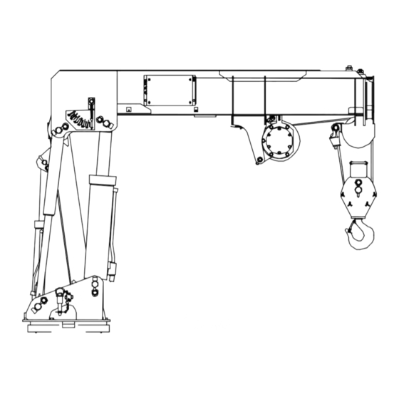
The system design allows you to operate the crane in an emergency situation or system failure without the DS 50 system in operation . In this situation leave the crane electric switch in the off position and press the override button while you operate the crane manually. - Page 7 DS50 TROUBLE SHOOTING MANUAL LEVEL 3 1. INTRODUCTION TO TROUBLESHOOTING THE PAT DS 50 LENGTH SENSOR - UNDER COVER- LENGTH CABLE DS 50 SYSTEM LENGTH CABLE ENTRY LENGTH CABLE MOUNT CABLE CONNECTORS BOOM MAST LOAD CELL PROXIMITY HOIST DRUM SWITCH...
-
Page 8: System Operation
DS50 TROUBLE SHOOTING MANUAL LEVEL 3 1. INTRODUCTION TO TROUBLESHOOTING THE PAT DS 50 1.2 SYSTEM OPERATION The Microprocessor Central Unit operates as the control center of the system. The length cable is connected to the boom nose. During telescoping the length cable spools off a drum which turns the length potentiometer using a gear assembly. -
Page 9: Troubleshooting Care
• Keep in mind while troubleshooting high quality electronic components to use caution and necessary care while testing and measuring DS 50 components and circuits of the crane electric's. • Tools and test equipment must be in good order and shall be inspected on a regular basis. - Page 10 DS50 TROUBLE SHOOTING MANUAL LEVEL 3 1. INTRODUCTION TO TROUBLESHOOTING THE PAT DS 50 Hookblock storage position Crane electric Crane power switch junction box Outrigger extend proximity switches- FMTV-Cargo only. Note: The drawing shows the model FMTV-W. The FMTV-C has only single line capability.
-
Page 11: The Hand Terminal
• The display (LCD): Indicates data and messages. The use of the hand terminal in connection with the DS 50 System is described in the course of the following instructions. Part of the hand terminal is a cable. The DB 9 connector at the end of the cable shall be connected to the interface ribbon cable which is connected into the DS 50 main board. - Page 12 DS50 TROUBLE SHOOTING MANUAL LEVEL 3 2.1 THE HAND TERMINAL Drawing 2.1.1 TSM DS 50-003/REV.B/031-300-190-003/12-02-96...
-
Page 13: The Hand Terminal Connection
In order to connect and use the hand terminal for data read-out or data adjustment the DS 50 hardware must be prepared as follows: • Switch the truck power off and remove the DS 50 central unit cover carefully as described in manual level 1&2. - Page 14 DS50 TROUBLE SHOOTING MANUAL LEVEL 3 2.2 THE HAND TERMINAL CONNECTION Drawing 2.2.1 TSM DS 50-003/REV.B/031-300-190-003/12-02-96...
- Page 15 DS50 TROUBLE SHOOTING MANUAL LEVEL 3 2.2 THE HAND TERMINAL CONNECTION Drawing 2.2.2 TSM DS 50-003/REV.B/031-300-190-003/12-02-96...
- Page 16 DS50 TROUBLE SHOOTING MANUAL LEVEL 3 2.2 THE HAND TERMINAL CONNECTION Drawing 2.2.3 TSM DS 50-003/REV.B/031-300-190-003/12-02-96...
-
Page 17: The Start Up Menu
Switch the truck power on. A cursor appears on the top left of the hand terminal display and the red ‘online’ LED lights up. After the DS 50 system has passed the selftest routine, the display shows the start up menu. Refer to drawing 3.1. -
Page 18: Displaying Data And Messages
In order to identify the needfor a data adjustment, internally calculated data must be compared with the actual measured data. The DS 50 is an overload shut down system and is not classified as a scale. The consideration of government specified tolerances is part of the trouble shooting process. - Page 19 DS50 TROUBLE SHOOTING MANUAL LEVEL 3 3.2 DISPLAYING DATA AND MESSAGES Drawing 3.2.1 TSM DS 50-003/REV.B/031-300-190-003/12-02-96...
-
Page 20: The Test Program
1 &2. Note: No other digital input is used for the DS 50 FMTV application. To return to the main menu press the >ESC< key or the letter key for the program you wish to select. - Page 21 DS50 TROUBLE SHOOTING MANUAL LEVEL 3 3.3 THE TEST PROGRAM Drawing 3.3.1 Drawing 3.3.2 TSM DS 50-003/REV.B/031-300-190-003/12-02-96...
-
Page 22: The On-Line Mode
Refer to the flowchart diagrams of this manual for detailed information how to use the two calibration functions. • Press the >K< key to return to the start up menu. Message > End online mode<. • Press either >U< or >V< key to switch between the two calibration functions. TSM DS 50-003/REV.B/031-300-190-003/12-02-96... - Page 23 DS50 TROUBLE SHOOTING MANUAL LEVEL 3 3.4 THE ON-LINE MODE Drawing 3.4.1 TSM DS 50-003/REV.B/031-300-190-003/12-02-96...
-
Page 24: Adjusting Calibration Data
Ensure that your measuring tape is in good condition. When testing the radius mount the beginning of the tape exactly on the center line of rotation. Note the display indicates the radius or boom length in resolution of 1/10 ft. - not in inches. TSM DS 50-003/REV.B/031-300-190-003/12-02-96... -
Page 25: Identify The Problem
Load display for the for the actual length actual length step and step too low or too high. angle too high or too low. Go to Go to Go to Go to section 6. section 7. section 8. section 9. TSM DS 50-003/REV.B/031-300-190-003/12-02-96... -
Page 26: Adjusting Overload Cut Off Factor
103%, 111%, 108% which does not meet the specification. Connect the hand terminal as described in section 2.2. Select the on-line mode as described in section 3.4. Press the key >U< . continue on next page TSM DS 50-003/REV.B/031-300-190-003/12-02-96... - Page 27 Press the key >K< to return to the start up menu. Go to section 3.2 and observe the display while you repeat the cut off test for the actual length step. Is the problem corrected now? Return to section 5 and identify the problem. The End TSM DS 50-003/REV.B/031-300-190-003/12-02-96...
-
Page 28: Adjusting Empty Hook Load Display
Select the on-line mode as described in section 3.4. Press the key >U< . Does the display indicate >C-EMPTY= n: < ? Note: n= calibration value. Scroll through the lines by pressing the enter key >CR< until the line is displayed. continue on next page TSM DS 50-003/REV.B/031-300-190-003/12-02-96... - Page 29 Press the key >K< to return to the start up menu. Go to section 3.2 and observe the hook display while you repeat booming down from high to low boom angle. Is the problem corrected now? Return to section 5 and identify the problem. The End TSM DS 50-003/REV.B/031-300-190-003/12-02-96...
-
Page 30: Adjusting Radius Display Under Load
Select the on-line mode as described in section 3.4. Press the key >U< . Does the display indicate >CF-RAD= n: < ? Note: n= calibration value. Scroll through the lines by pressing the enter key >CR< until the line is displayed. continue on next page TSM DS 50-003/REV.B/031-300-190-003/12-02-96... - Page 31 Press the key >K< to return to the start up menu. Go to section 3.2 and repeat testing the radius under load. Is the problem corrected now? Return to section 5 and identify the problem. The End TSM DS 50-003/REV.B/031-300-190-003/12-02-96...
-
Page 32: Adjusting Load Display
In example >C-LOAD I= -200< -- with a calculated correction factor of -- 4% enter >C-LOAD I= -600<. Note: The correction value is limited to +/- 1000 = +/- 10%. The program extrapolates the entry and writes the calculated values into the next stored angles continue on next page TSM DS 50-003/REV.B/031-300-190-003/12-02-96... - Page 33 Refer to previous page reference of stored angles. Press the key >CR< to change to the new correction factor. Repeat until you have entered all previously calculated correction factors for the stored angles. The End TSM DS 50-003/REV.B/031-300-190-003/12-02-96...
-
Page 34: Transferring Eeprom Data
DS50 TROUBLE SHOOTING MANUAL LEVEL 3 10. TRANSFERRING EEPROM DATA In the event of DS 50 main board failure it becomes necessary to install a replacement central unit. Note: All calibration data is stored in the E-EPROM which is installed on the main board and not removable. - Page 35 DS50 TROUBLE SHOOTING MANUAL LEVEL 3 10. TRANSFERRING EEPROM DATA Drawing 10.1.1 TSM DS 50-003/REV.B/031-300-190-003/12-02-96...
- Page 36 --> Press the white >FILL< key. Display indicates in example 00000,0FFFF,FF. --> Enter: 00000,07FFF,FF using the keyboard of the DATAMAN and confirm with the >ENTER< key. DATAMAN S4 answers with one short tone and returns to the prompt. TSM DS 50-003/REV.B/031-300-190-003/12-02-96...
- Page 37 Switch DATAMAN S4 off and immediately on again. The DATAMAN S4 will now receive the data out of the EEPROM. Note: The DATAMAN S4 will transmit the data one more time to the DS 50 to test the received data. Please be patient as the transmission can take a little while.
- Page 38 LEVEL 3 10. TRANSFERRING EEPROM DATA At this point it is possible to burn and secure the data into an EPROM (27C256 PAT tested and approved EPROMS only). The EPROM can be downloaded to a PC file using the DATAMAN S4.
- Page 39 “Transmit data to the DS 50” in this section. Read EPROM data into the DATAMAN S4 • Switch the truck power off (No power to DS 50) • Disconnect the serial interface cable from the DB 9 ribbon cable connector of the DS 50 interface.
-
Page 40: Overload Warning
Connect the DB 9 connector of the interface cable into the DB 9 ribbon cable connector of the DS 50 interface. • Switch DATAMAN S4 on and switch the truck power (DS 50 power) on. Wait for minimum of 10 seconds. The display will prompt twice (>) with two tones and the cursor flashes. -
Page 41: Error Code Messages
E0 2 No loadchart radius or Boom is lowered too low into Raise the boom to a radius angle available with low a non rated radius or angle or angle specified in the load boom angle. range. chart. TSM DS 50-003/REV.B/031-300-190-003/12-02-96... - Page 42 Identify clearly a main board defect by referring to the troubleshooting manual. If in doubt contact PAT service support. Replace main board or central unit and transfer E-Eprom data. Load test system after. Length potentiometer Replace length defective.
- Page 43 Identify clearly a main board circuit in the wiring. defect by referring to the troubleshooting manual. If in doubt contact PAT service support. Replace main board or central unit and transfer E-Eprom data. Load test system after.
- Page 44 Follow the instruction in the troubleshooting manual and use the test unit to identify clearly a load cell defect. If in doubt contact the PAT service support. In the event of a load cell defect replace load cell referring to the...
- Page 45 Analog channel on main Identify clearly a main board board defective. defect by referring to the troubleshooting manual. If in doubt contact PAT service support. Replace main board or central unit and transfer E-Eprom data. Load test system after. TSM DS 50-003/REV.B/031-300-190-003/12-02-96...
- Page 46 Follow the instruction in the troubleshooting manual and use the test unit to identify clearly a load cell defect. If in doubt contact the PAT service support. In the event of a load cell defect replace load cell referring to the...
- Page 47 E-Eprom data. Load test system after. E4 1 Error in the internal Microprocessor components If in doubt contact PAT write/ read memory defective on main board. service support. Replace (RAM) of the main board or central unit microprocessor.
- Page 48 Refer to troubleshooting manual level 3. Defective E-Eprom - when the If in doubt contact PAT E-Eprom was loaded with service support. Replace calibration data previously. main board or central unit and transfer original E- Eprom data.
-
Page 49: Removing Test And Calibration Equipment
• Remove jumper plug J2 if used for the hand terminal operation. Store the jumper plug in a safe and secure area. The jumper plug is needed for whenever you connect the hand terminal to the DS 50. • Disconnect the external cables from the Mil type connectors. - Page 50 • Check the system performance by lifting a known test load and a cut off test. • If the test fails then you should verify the correct removal of test equipment or calibration equipment or repeat trouble shooting as described in Troubleshooting Manual level 1,2 and 3. TSM DS 50-003/REV.B/031-300-190-003/12-02-96...
Need help?
Do you have a question about the DS 50 and is the answer not in the manual?
Questions and answers