PAT DS 50 Operator's Manual
Load moment indicator
Hide thumbs
Also See for DS 50:
- Troubleshooting manual (51 pages) ,
- Troubleshooting manual (50 pages) ,
- Troubleshooting manual (45 pages)

Related Manuals for PAT DS 50


Summary of Contents for PAT DS 50
- Page 1 LOAD MOMENT INDICATOR DS 50 / 0002 OPERATOR'S MANUAL MANITEX Second Edition 03/18/1997 – CSH (con:K2AA V1.0) 031-300-190014_A.doc...
- Page 3 The information in this document is subject to change without notice. PAT does not assume any warranty of any kind with regard to this material, including, but not limited to the implied warranties of marketability and fitness for a particular purpose.
-
Page 5: Table Of Contents
TABLE OF CONTENTS General Information Warnings System Description System Function Control Identification Pre-Operational Inspection Anti two-block devices Pre- Operation Inspection and Calibration Verification System Operation Operating Mode Selection Selection of the Reeving Data Display Error Display System and Display test Service and Maintenance Troubleshooting Second Edition 03/18/1997 –... -
Page 6: General Information
The LMI provides the operator with information regarding the length and angle of the boom, working radius, rated load and the total calculated weight being lifted by the crane. If non-permitted conditions are approached, the DS 50 Load Moment Indicator will warn the operator by sounding an audible alarm and lighting a warning light. -
Page 7: System Description
3 SYSTEM DESCRIPTION The PAT Load Moment Indicator DS 50 consists of a central micro processor unit with build in length- and angle sensor, operating console, pressure transducers, and anti-two block switch(es). The system operates on the principle of reference/real comparison. The real value, resulting from the pressure measurement is compared with the reference data, stored in the central processor memory and evaluated in the microprocessor. - Page 8 Operator's Manual DS 50 / 0002 Fig. 1: Components of the LMI system PAT DS 50...
-
Page 9: System Function
Operator's Manual DS 50 / 0002 3.1 System Function Upon switching on, the system starts with an automatic test of the LMI system, of lamps and audible alarm. During the test, the LC display shows 8:88.8.8 First, the operating mode is determined by... -
Page 10: Control Identification
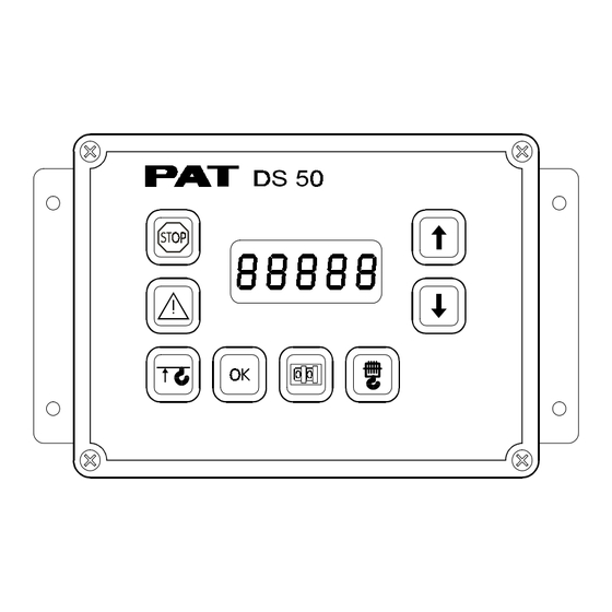
Operator's Manual DS 50 / 0002 3.2 Control Identification This unit contains a display and different controls that are described as follows: Fig. 2: Operating Console 1 LC Display 2 Load Moment Limit Light 3 Load Moment Prewarning Light 4 Alarm Light “Anti-Two-Block”... - Page 11 Operator's Manual DS 50 / 0002 LC-Display The LC Display has five digits. The readout depends on the operating modus and the operator’s selection. Please refer to section 4, Operation of the system. Load Moment Limit Light The red LOAD MOMENT LIMIT LIGHT (2) warns the operator that a rated load condition has been reached.
- Page 12 Operator's Manual DS 50 / 0002 Cursor "up" Key for the stepwise increase of the displayed value: • when selecting the operation code • when selecting the reeving • when selecting the geometry data (➭ refer to chapter 5.3) Cursor "down"...
-
Page 13: Pre-Operational Inspection
Operator's Manual DS 50 / 0002 4 Pre-Operational Inspection Prior to operating the crane, the following electrical connections must be checked to ensure that the system is properly connected for the crane configuration. 4.1 Anti two-block devices If the crane works only with the main boom and without boom extension, check the weight to ensure it is attached to the anti two-block switch on the main hoist load line. -
Page 14: Pre-Operation Inspection And Calibration Verification
Operator's Manual DS 50 / 0002 Pre-Operation Inspection and Calibration Verification After the electrical connections have been checked to insure that the system is properly connected for the crane configuration, the following checks shall be made: 1. Check the electrical wiring connecting the various parts of the system for physical damage. - Page 15 If any of the displays reflects a deviation between displayed and actual values, an authorized PAT service representative shall be called for repair of the system and/or verification of the crane’s LMI calibration.
-
Page 16: System Operation
DS 50 / 0002 5 SYSTEM OPERATION The LMI System DS 50 allows the operator to assess and evaluate the lift to meet the manufacturer specified load charts for the crane. The correct setting is of utmost importance for the proper functioning of the system and the crane. -
Page 17: Selection Of The Reeving
Troubleshooting 5.2 Selection of the Reeving (parts of line) (automatically after finishing operation mode selection) manually upon modification of the reeving by start function: pressing key The reeving key and the cursor keys light up. The reeving selection is displayed: XX= present reeving select •... -
Page 18: Data Display
Operator's Manual DS 50 / 0002 5.3 Data Display In case neither the operating mode selection nor the reeving selection are active, the LC display serves as data display: Press keys to select the values. There are 9 display positions:... -
Page 19: Error Display
Troubleshooting 5.4 Error Display In case of operating error or system malfunction an error code is displayed. (for detailed information refer to chapter 7 troubleshooting) Error messages are given priority on the display: XX=error code Press key to acknowledge an error message (exception: console error messages) 5.5 System and Display Test Press keys simultaneously to select the test function. -
Page 20: Troubleshooting
Operator's Manual DS 50 / 0002 7 TROUBLESHOOTING General In case of a malfunction of the system, the display (1) will indicate a code that identifies the system malfunction. The error codes listed in the Malfunction Table will identify various faults that can occur with the LMI. - Page 21 Troubleshooting Operating Errors Malfunctions in the system that are caused by range exceeding or operating errors by the crane operator himself are indicated on the display. These error codes are E01, E02, E03, E04, and the crane operator himself can normally eliminate E05 and them. Error Cause Elimination...
Need help?
Do you have a question about the DS 50 and is the answer not in the manual?
Questions and answers