MINN KOTA RIPTIDE ULTERRA Owner's Manual
Bow-mount trolling motor
Hide thumbs
Also See for RIPTIDE ULTERRA:
- User manual ,
- Installation instructions manual (49 pages) ,
- Owner's manual (48 pages)
Table of Contents
Advertisement
Advertisement
Table of Contents
Troubleshooting

Related Manuals for MINN KOTA RIPTIDE ULTERRA


Summary of Contents for MINN KOTA RIPTIDE ULTERRA
- Page 1 RIPTIDE ULTERRA ™ BOW-MOUNT TROLLING MOTOR Owner's Manual...
- Page 2 THANK YOU Thank you for choosing Minn Kota. We believe that you should spend more time fishing and less time positioning your boat. That’s why we build the smartest, toughest, most intuitive trolling motors on the water. Every aspect of a Minn Kota trolling motor is thought out and rethought until it’s good enough to bear our name.
-
Page 3: Table Of Contents
Change the Prop Orientation .................. 30 Adjusting the Lift Belt ................... 33 Greasing the Latch Pin and Power Tilt Motor Shaft ........... 33 Stowing from the Riptide Ulterra Motor ..............34 Trim/Stow Reset Procedure ..................35 Manually Stowing the Riptide Ulterra..............36 SERVICE &... -
Page 4: Safety Considerations
WARNING You are responsible for the safe and prudent operation of your vessel. We have designed your Minn Kota product to be an accurate and reliable tool that will enhance boat operation and improve your ability to catch fish. This product does not relieve you from the responsibility for safe operation of your boat. -
Page 5: Warranty
Products purchased outside of the U.S. must be returned prepaid with proof of purchase (including the date of purchase and serial number) to any Authorized Minn Kota Service Center in the country of purchase. -
Page 6: Know Your Boat
KNOW YOUR bOaT Port Starboard Inboard Outboard Keel Port Starboard Gunwale Transom Stern Gunwale Stern Hull 6 | minnkotamotors.com ©2019 Johnson Outdoors Marine Electronics, Inc. -
Page 7: Features
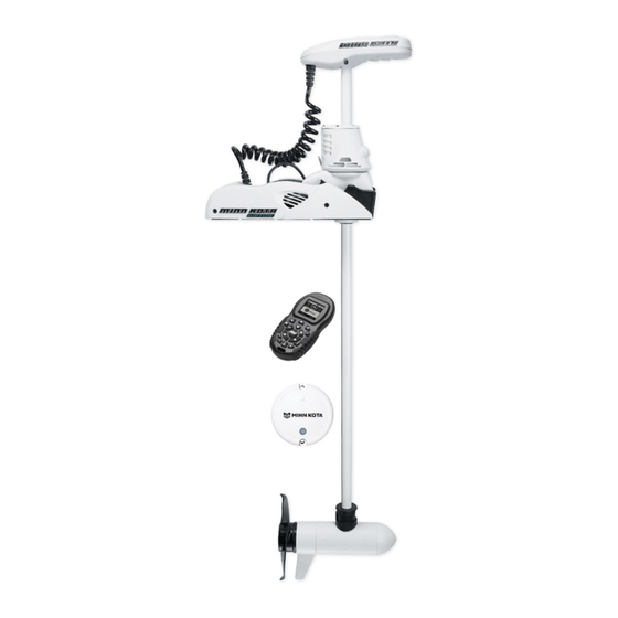
feaTURes Integrated i-Pilot Power Button Control Head Status Indicator System Ready Indicator Power Trim Indicator Panel Motor Mount Auto Stow/Deploy Lifetime Warranty Flexible Composite Shaft Cool Quiet Power Motor Weedless Wedge 2 Propeller NOTICE: Specifications subject to change without notice. This diagram is for reference only and may differ from your actual motor. -
Page 8: Installation
INSTALLING THE RIPTIDE ULTERRA Your new Riptide Ulterra comes with everything you’ll need to directly install it to the boat. This motor can be directly mounted to the boat or it may be coupled with a Minn Kota quick release bracket for ease of mounting and removal. For installation with a quick release bracket, refer to the installation instructions provided with the bracket. -
Page 9: Installing The Riptide Ulterra
INSTALLING THE RIPTIDE ULTERRA MOUNTING CONSIDERATIONS It is recommended that the motor be mounted as close to the keel or centerline of the boat as possible. Make sure the area under the mounting location is clear to drill holes View accessories and install nuts and washers. - Page 10 INSTALLING THE RIPTIDE ULTERRA Under the Left Sideplate, the Extension Damper obstructs access to the left front Mounting Hole. Using a small Screw Driver, remove the two 5/16" e-clips holding the Extension Damper in place. Once the e-clips are removed, slide the Extension...
- Page 11 INSTALLING THE RIPTIDE ULTERRA ITEM(S) NEEDED #7 x 6 WARNING CAUTION Do not deploy the motor until it is fully mounted to the boat. Failure to allow 1-1/2" of clearance of the Shaft when mounting Illustrations are for reference only. Deploying your motor may cause failures when the motor stows and deploys.
- Page 12 NOTICE: The Long Bolts, Flat Washers and Nylock that run along side of the Base Extrusion when installing and Nut are not used when installing the Riptide Ulterra tightening the motor mounting bolts. with a Quick Release Bracket. 12 | minnkotamotors.com...
- Page 13 Washer and Rubber Washer and into place. NOTICE: The Short Bolts are not used when installing the Riptide Ulterra directly to the boat. Slide the Base Extrusion into place under the Bolts that were just installed. If installing with a Quick Release Bracket, the Base...
- Page 14 Mounting Holes into a Quick Release Bracket. NOTICE: The Long Bolts, Flat Washers and Nylock Nut are not used when installing the Riptide Ulterra with a Quick Release Bracket. Hex Head Bolt If installing directly to the boat deck, install the...
- Page 15 INSTALLING THE RIPTIDE ULTERRA At this point in the installation process the Motor should be secured to the deck of the boat, and the Motor can now be reassembled. The Extension Damper can be slid back in place on the Damper Pins.
-
Page 16: Routing And Connecting I-Pilot Link Cables
Link system. If no connections are present, your motor may or may not be installed with i-Pilot. Please follow the Minn Kota recommendations on routing the cables to optimize mobility and maximize functionality. - Page 17 ROUTING AND CONNECTING I-PILOT LINK CABLES The i-Pilot Link cable should be fed all the way Control Head through the Coil Cord. They should exit the Coil Cord at the bottom of the Coil Cord, where it connects to the Motor Mount. i-Pilot Link NOTICE:...
-
Page 18: Battery Wiring & Installation
CAUTION These guidelines apply to general rigging to support your Minn Kota motor. Powering multiple motors or additional electrical devices from the same power circuit may impact the recommended conductor gauge and circuit breaker size. If you are using wire longer than that provided with your unit, follow the conductor gauge and circuit breaker sizing table below. -
Page 19: Selecting The Correct Batteries
(flooded, AMG or GEL). Lithium Ion batteries maintian higher voltages for longer periods of time than lead acid. Therefore, running a Minn Kota trolling motor at speeds higher than 85% for a prolonged peiod could cause permanent damage to the motor. -
Page 20: Connecting The Batteries In Series
CONNECTING THE BATTERIES IN SERIES The negative (-) connection must be connected to the negative terminal of the same battery that the trolling motor negative lead connects to. In the diagrams below this battery is labeled “Low Side” Battery. Connecting to any other trolling motor battery will input positive voltage into the “ground”... - Page 21 CONNECTING THE BATTERIES IN SERIES 36 Volt Systems Three 12 volt batteries are required. The batteries must be wired in series, only as directed in wiring diagram, to provide 36 volts. Make sure that the motor is switched +36 Volts to trolling motor off (speed selector on “0”).
-
Page 22: Motor Wiring Diagram
MOTOR WIRING DIaGRaM RIPTIDE ULTERRA WITH i-PILOT OR i-PILOT LINK The following Motor Wiring Diagram applies to all Riptide Ulterra models that come factory installed with either i-Pilot or i-Pilot Link. Black M- Accessory Attachment Red M+ Control Head Plunger... -
Page 23: Using & Adjusting The Motor
Power Button The Riptide Ulterra must be powered “on” and “off” manually. The remote will not turn the motor “on” or “off”. The Power button located on the base of the motor on the Indicator Panel. Press the Power button to turn the motor “on”. When the motor is in the stowed... - Page 24 The Emergency Strap should be secured every time the motor is manually stowed to prevent damage from high wind, rough water or vibrations, including while the boat is trailered. See the “Manually Stowing the Riptide Ulterra” section of the manual for more information on when the Emergency Strap is needed.
-
Page 25: Quick Stow & Deploy
QUICK STOW & DEPLOY QUICK STOW & DEPLOY Deploying the Motor with i-Pilot Press the Home button. Use the Menu Up and Menu Down buttons to find the Deploy menu at the bottom of the display screen. NOTICE: The Deploy menu at the bottom of the display screen can only be found when the motor is stowed. - Page 26 QUICK STOW & DEPLOY Use the Right Softkey to select the Stow menu. Once selected the motor will automatically stow. WARNING As soon as the Stow menu is selected, the motor will automatically stow. Be sure the motor is clear from obstructions and has a clear path of travel.
- Page 27 QUICK STOW & DEPLOY Once in the Ulterra Menu, find the Deploy button and select it. The Deploy button requires a double press to engage. WARNING As soon as the Deploy button is selected, the motor will automatically deploy. Be sure the motor is clear from obstructions and has a clear path of travel.
- Page 28 QUICK STOW & DEPLOY Stowing the Motor with i-Pilot Link Press the Home button. Scroll through the Content Area using either your finger or the Screen Navigation button to find the Ulterra button. Select the Ulterra button using either your finger or by pressing the Ok button to open the Ulterra Menu.
-
Page 29: Installing An External Transducer
INSTALLING AN EXTERNAL TRANSDUCER INSTALLING AN EXTERNAL TRANSDUCER An external transducer is not included with your trolling motor. An external transducer can be installed onto motors that do not have a built in transducer. Mount the External Transducer according to directions provided with the transducer. -
Page 30: Change The Prop Orientation
CHANGE THE PROP ORIENTATION MOTOR ADJUSTMENTS CHANGE THE PROP ORIENTATION When the motor is mounted onto the boat, the orientation of the Prop may be changed to either Inboard or Outboard to accommodate different boat cover configurations. Complete the following steps to change prop orientation. WARNING When the motor is powered “off”... - Page 31 CHANGE THE PROP ORIENTATION Locate the Trim Release Handle on the Side of the Trim Housing Trim Housing. Grasp the Trim Release Handle and pull it out. WARNING Trim Release Handle When using the Trim Handle or moving the Trim Housing, keep fingers clear of all hinges, pivot points and all moving parts above and below the Trim Housing.
- Page 32 CHANGE THE PROP ORIENTATION Once in the proper orientation, lower the Trim Trim Housing Housing and Shaft onto the Steering Housing. Trim Release Let the Trim Release Handle move back in place. Handle Trim Housing Shaft Steering Trim Release Housing Handle Reconnect the Power Cables to the battery and make sure the breaker, if equipped, is turned “on”.
-
Page 33: Adjusting The Lift Belt
GREASING THE LATCH PIN AND POWER TILT MOTOR SHAFT In order for the Riptide Ulterra to continue running at optimum performance, it is recommended that the Latch Pin and the Motor Shaft for the Power Tilt be greased every season. It is recommended to use a marine grade grease. -
Page 34: Stowing From The Riptide Ulterra Motor
Lower Unit STOWING FROM THE RIPTIDE ULTERRA MOTOR In the unlikely event your i-Pilot or i-Pilot Link remote becomes non-functioning, you can stow the Riptide Ulterra from the base of the motor. Locate the Indicator Panel at the base of the Mount. -
Page 35: Trim/Stow Reset Procedure
TRIM/STOW RESET PROCEDURE In the unlikely event Riptide Ulterra will not trim or stow, the following procedure will reset the motor and restore functionality. If Riptide Ulterra does not reset, repeat the procedure. If the second attempt fails, please contact your local authorized service center or call Minn Kota service at (800) 227-6433. -
Page 36: Manually Stowing The Riptide Ulterra
Trim/Stow Reset Procedure Stowing from the Riptide Ulterra Motor If your batteries lose power to the level that the motor will not stow, the motor will most likely stall at a 45 degree angle. - Page 37 MANUALLY STOWING THE RIPTIDE ULTERRA Using a #2 Phillips Screwdriver, loosen the screw on the Manual Tilt Knob. The Manual Tilt Knob holds two Metal Plates together. Using a Flat Blade Screwdriver pry up on the Manual Tilt Knob until it releases from the Metal Plates.
- Page 38 MANUALLY STOWING THE RIPTIDE ULTERRA While the Trim Housing and Shaft are lifted up, release the Latch Pin Bracket. Lift the Trim Housing, Shaft and Lower Unit up, and Trim Housing rotate it. Latch Pin Pull the Lower Unit onto the Mount Ramps.
- Page 39 MANUALLY STOWING THE RIPTIDE ULTERRA While the motor is in the stowed position, use a #3 Phillips Screwdriver, to replace the Right Sideplate, if desired. Do this by replacing the two screws that hold the sideplate in place. Screw Right...
-
Page 40: Service & Maintenance
seRVICe & MaINTeNaNCe PROPELLER REPLACEMENT TOOLS AND RESOURCES REQUIRED • 9/16” Open End Wrench • Flat Blade Screwdriver INSTALLATION Disconnect the motor from all sources of power prior to changing the propeller. Armature Drive Pin Shaft Hold the propeller and loosen the Prop Nut with a pliers or a wrench. -
Page 41: General Maintenance
GENERAL MAINTENANCE GENERAL MAINTENANCE • After every use, the entire motor should be rinsed with freshwater, then wiped down with a cloth dampened with an aqueous based silicone spray. Do not spray water into the ventilation openings in the head of the motor. •... - Page 42 TROUBLESHOOTING Motor fails to trim: • Check main lift belt tension per the Adjustments section. Motor fails to stow or deploy: • Check for obstructions preventing the motor from deploying or stowing. • Ensure that manual tilt knob is engaged. See the Emergency Stow Procedure section for details. •...
-
Page 43: Advanced Troubleshooting
Outdoors Inc. is not responsible for any damage due to improper rigging or installation. If you do not have the skills, experience and tools to perform the following maintenance and repairs, we recommend you seek the help of a Minn Kota Authorized Service Center. - Page 44 ADvANCED TROUBLESHOOTING If it has come loose, connect the motor to the appropriate voltage. The power can be switched ON by reaching in with a small object (a blade screwdriver, for example) and pressing down on the actuator of the Power switch. The green and red LEDs should light up and the RT Ulterra can then be deployed via the corded foot pedal or the remote in the normal manner.
- Page 45 Case 3 Riptide Ulterra motor will not deploy when the Stow/Deploy button on the foot pedal or the i-Pilot and i-Pilot Link remote is pressed. When troubleshooting, determine if an error tone is present or not and proceed to either the No Error Tone or Error Tone sections below.
- Page 46 The cutting of any of the sensor wires will cause the motor to be inoperative. CORRECTIVE ACTION: Seek the help of a Minn Kota Authorized Service Center. A list of Authorized Service Centers can be found at minnkotamotors.com/support/service-providers/locate. Contact our Technical Service Department by email or, by dialing 800-227-6433.
- Page 47 ADvANCED TROUBLESHOOTING Case 4 12:53 PM Foot Pedal i-Pilot Link Remote AUTOPILOT SPOT-LOCK PROP Motor is deployed with the motor lower unit less than 14-15 AUTOPILOT MODE SPOT-LOCK MODE inches below the aluminum base extrusion, it will not steer in CONSTANT CONSTANT either direction and the motor lower unit will not run.
- Page 48 ADvANCED TROUBLESHOOTING Send a command to stow the motor via the remote 12:53 PM Foot Pedal i-Pilot Link Remote or Foot Pedal. Allow the Ulterra motor to steer the AUTOPILOT SPOT-LOCK lower unit, raise straight up, rotate the shaft and MODE AUTOPILOT SPOT-LOCK...
- Page 49 ADvANCED TROUBLESHOOTING Case 6 The Ulterra motor does not rotate into the horizontal position when stowing, or the vertical position when deploying, at the appropriate time. During the stow sequence the motor lower unit should come straight up and begin to rotate into the horizontal position when the lower unit is about twelve (12) to thirteen (13) inches below the aluminum base extrusion.
-
Page 50: For Further Troubleshooting And Repair
Authorized Service Centers Minn Kota has over 800 authorized service providers in the United States and Canada where you can purchase parts or get your products repaired. Please visit our Authorized Service Center page on our website to locate a service provider in your area. -
Page 51: Compliance Statements
Minn Kota motors are not subject to the disposal regulations EAG-VO (electric devices directive) that implements the WEEE directive. Nevertheless never dispose of your Minn Kota motor in a garbage bin but at the proper place of collection of your local town council. - Page 52 FCC COMPLIANCE FCC COMPLIANCE This device complies with Part 15 of the FCC rules. Operation is subject to the following two conditions: This device may not cause harmful interference. This device must accept any interference that may be received, including interference that may cause undesired operation. Changes or modifi...
-
Page 53: Parts Diagram & Parts List
RIPTIDE ULTERRA - 80/112 LBS THRUST - 24/36 vOLT - 54"/60"/72" SHAFT The parts diagram and parts list provides Minn Kota® WEEE compliance disassembly instructions. For more information about where you should dispose of your waste equipment for recycling and recovery and/or your European Union member state requirements, please contact your dealer or distributor from which your product was purchased. - Page 54 PARTS DIAGRAM & PARTS LIST Control Head Parts List Assembly Part # Description Notes Quantity 2774116 iPILOT CONTRLR 1.6 RT ULT 2774118 iPLINK CONTRLR 3.0 RT ULT Â 2994075 REMOTE ASSY, IPILOT 1.6 2994076 REMOTE ASSY, IPILOT LINK Â Item Part # Description Notes...
- Page 55 PARTS DIAGRAM & PARTS LIST Item Part # Description Notes Quantity 2394900 INSTRUCTIONS, HEADING SENSOR 2207114 MANUAL,INSTALL GUIDE,RT ULT BT 2207112 MANUAL, RT ULTERRA BT 2207105 QUICK REFERENCE GUIDE, ULTERRA 2297165 MANUAL-DISCLAIMER,DWNLOAD INFO Not shown on Parts Diagram. This part is included in an assembly and cannot be ordered individually. ✖...
- Page 56 PARTS DIAGRAM & PARTS LIST RIPTIDE ULTERRA MOTOR 24 Volt 4" Parts Diagram 80lbs Thrust 126 92 88 90 80 124 94 96 108 56 | minnkotamotors.com ©2019 Johnson Outdoors Marine Electronics, Inc.
- Page 57 PARTS DIAGRAM & PARTS LIST 24 Volt 4" Motor Parts List Assembly Part # Description Notes Quantity 2417037 MTR/TUBE ASSY 80# 54" RT *MOTOR & TUBE* 2417038 MTR/TUBE ASSY 80# 60" RT *MOTOR & TUBE* 2417037 MTR/TUBE ASSY 80# 54" RT *MOTOR &...
- Page 58 PARTS DIAGRAM & PARTS LIST Item Part # Description Notes Quantity 973-025 SPACER - BRUSHPLATE 990-051 WASHER - STEEL THRUST 990-052 WASHER - NYLATRON 992-010 WASHER - BELLEVILLE 990-045 SPACER - THRUST 188-094 BRUSH W/TERMINAL BRUSH HOLDER ✖ 9-738-015 BRUSH PLATE-4" terminal RIVET-.25"...
- Page 59 PARTS DIAGRAM & PARTS LIST RIPTIDE ULTERRA MOTOR 36 Volt 4.5" Motor Parts Diagram 112lbs Thrust 192 168 minnkotamotors.com | 59 ©2019 Johnson Outdoors Marine Electronics, Inc.
- Page 60 PARTS DIAGRAM & PARTS LIST 36 Volt 4.5" Motor Parts List Assembly Part # Description Notes Quantity 2417097 MTR/TUBE ASSY 112# 60" RT *MOTOR & TUBE* 2417086 MTR/TUBE ASSY 112# 72" RT *MOTOR & TUBE* 2777347 CTR HSG ASY, CB, 112#, SW, 60" TUBE *TUBE* 2777348 CTR HSG ASY, CB, 112#, SW, 72"...
- Page 61 PARTS DIAGRAM & PARTS LIST Item Part # Description Notes Quantity RIVET-.25" ✖ 975-045 SPRING-TORSION TERMINAL 1/4" MALE TAB-THREE ✖ 640-045 LEADWIRE BLK 10AWG 76 1/2" GPT *60* 640-049 LEADWIRE BLK 10AWG 88.50" GPT *72* 640-145 LEADWIRE RED 10AWG 75 7/8" GPT *60* 640-149 LEADWIRE RED 10AWG 88"...
- Page 62 PARTS DIAGRAM & PARTS LIST RIPTIDE ULTERRA STEERING HOUSING Steering Housing Parts Diagram 62 | minnkotamotors.com ©2019 Johnson Outdoors Marine Electronics, Inc.
- Page 63 PARTS DIAGRAM & PARTS LIST Steering Housing Parts List Assembly Part # Description Notes Quantity 2776524 ASM, STEERING 36V SW *112LB THRUST* 2776523 ASM, STEERING 24V SW *80LB THRUST* 2772200 OUTPUT GEAR W/MAGNETS 2770100 RELEASE KNOB WITH SCREW KIT Item Part # Description Notes...
- Page 64 PARTS DIAGRAM & PARTS LIST Item Part # Description Notes Quantity MAGNET-.187X.125 NCKL PLT(N/A) ✖ 2201510 COLLAR-DRIVE, OUTPUT TUBE 2321510 COLLAR-DRIVE,BOTTOM 2321704 WASHER-THRUST, STEERING 2321720 SHIM,O-RING 2324608 O-RING,224,PD PRO STR HSG 2327314 BUSHING, PRO STEERING SW 2327315 BUSHING,ALUMIN. SPACER ST 2324604 O-RING, CASE SEAL 2308601...
- Page 65 PARTS DIAGRAM & PARTS LIST RIPTIDE ULTERRA TRIM HOUSING Trim Housing Parts Diagram minnkotamotors.com | 65 ©2019 Johnson Outdoors Marine Electronics, Inc.
- Page 66 PARTS DIAGRAM & PARTS LIST Trim Housing Parts List Assembly Part # Description Notes Quantity 2997825 ASSY,TRIM MOD "M",SW, 72" *M SKU* *EUROPE ONLY* 2997821 ASSY,TRIM MODULE, SW, 72" 2997824 ASSY,TRIM MOD "M",SW, 60" *M SKU* *EUROPE ONLY* 2997804 ASSY,TRIM MODULE, SW, 60" 2997808 ASSY,TRIM MODULE, SW, 54"...
- Page 67 PARTS DIAGRAM & PARTS LIST Item Part # Description Notes Quantity 2206912 GASKET, TRIM HSG ASM, LEFT,WHT 2206913 GASKET, TRIM HSG ASM, RGHT,WHT 3394602 WASHER-FLAT #8 SS MOTOR, TRIM ✖ PLATE-ADAPTER, LIFT MOTOR ✖ SCREW-M4 X 10 PFH, ZP ✖ PULLEY, LIFT MOTOR, MACHINED ✖...
- Page 68 PARTS DIAGRAM & PARTS LIST RIPTIDE ULTERRA MOUNT Mount Parts Diagram 68 | minnkotamotors.com ©2019 Johnson Outdoors Marine Electronics, Inc.
- Page 69 PARTS DIAGRAM & PARTS LIST Mount Parts List Assembly Part # Description Notes Quantity 2774080 MAIN CTRL BD, US/AU/CA, 24V, 60" *80LB THRUST* *60* 2774082 MAIN CTRL BD, US/AU/CA, 36V, 60" *112LB THRUST* *60* 2774084 MAIN CTRL BD, EUR, 24V, 60" *80LB THRUST* *60* *M SKU EUROPE* 2774086 MAIN CTRL BD, EUR, 36V, 60"...
- Page 70 PARTS DIAGRAM & PARTS LIST Item Part # Description Notes Quantity 2201723 WASHER-#6, .625 OD, SS 2373440 SCREW-#4-24 X 1/4 PHCR SS TY B 2263453 SCREW-1/4-20 X 1" SHCS S/S 2200825 CLIP, SENSOR CABLE 2208803 DAMPER, SS, 112# *112 LB THRUST* 2208801 DAMPER, SS, 80# *80 LB THRUST*...
- Page 71 PARTS DIAGRAM & PARTS LIST Item Part # Description Notes Quantity 2201725 WASHER-CLIPPED, 1/4", 1.00" OD 2261713 WASHER-1/4 FLAT 18-8 SS 2263103 NUT-1/4-20 NYLOCK SS 2301720 WASHER-MOUNTING - RUBBER 2202903 STANDOFF,OIL DAMPENER,SW 2200823 CLIP, POWER BUTTON 2203440 SCREW-#4-40 X 1/4 PPH SS 2203801 STRAP, HOLD DOWN Not shown on Parts Diagram.
- Page 72 Stop buying new batteries and start taking care of the ones you’ve got. Many chargers can actually damage your battery over time – creating shorter run times and shorter overall life. Digitally controlled Minn Kota chargers are designed to provide the fastest charge that protect and extend battery life.
Need help?
Do you have a question about the RIPTIDE ULTERRA and is the answer not in the manual?
Questions and answers