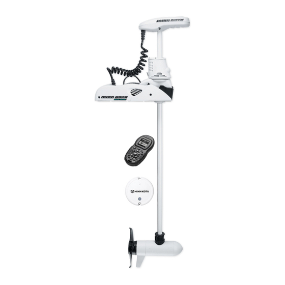
MINN KOTA RIPTIDE ULTERRA Installation Instructions Manual
Bow-mount trolling motor
Hide thumbs
Also See for RIPTIDE ULTERRA:
- User manual ,
- Owner's manual (72 pages) ,
- Quick start up manual (2 pages)
Table of Contents
Advertisement
Available languages
Available languages
Quick Links
Advertisement
Table of Contents

Related Manuals for MINN KOTA RIPTIDE ULTERRA


Summary of Contents for MINN KOTA RIPTIDE ULTERRA
- Page 1 RIPTIDE ULTERRA ™ BOW-MOUNT TROLLING MOTOR Installation Instructions...
-
Page 2: Motor Information
THANK YOU Thank you for choosing Minn Kota. We believe that you should spend more time fishing and less time positioning your boat. That’s why we build the smartest, toughest, most intuitive trolling motors on the water. Every aspect of a Minn Kota trolling motor is thought out and rethought until it’s good enough to bear our name. -
Page 3: Safety Considerations
WARNING You are responsible for the safe and prudent operation of your vessel. We have designed your Minn Kota product to be an accurate and reliable tool that will enhance boat operation and improve your ability to catch fish. This product does not relieve you from the responsibility for safe operation of your boat. -
Page 4: Know Your Boat
KNOW YOUR BOAT Port Starboard Inboard Outboard Keel Port Starboard Gunwale Transom Stern Gunwale Stern Hull 4 | minnkotamotors.com ©2019 Johnson Outdoors Marine Electronics, Inc. -
Page 5: Installation
INSTALLING THE RIPTIDE ULTERRA Your new Riptide Ulterra comes with everything you’ll need to directly install it to the boat. This motor can be directly mounted to the boat or it may be coupled with a Minn Kota quick release bracket for ease of mounting and removal. For installation with a quick release bracket, refer to the installation instructions provided with the bracket. - Page 6 INSTALLING THE RIPTIDE ULTERRA MOUNTING CONSIDERATIONS It is recommended that the motor be mounted as close to the keel or centerline of the boat as possible. Make sure the area under the mounting location is clear to drill holes View accessories and install nuts and washers.
- Page 7 INSTALLING THE RIPTIDE ULTERRA Under the Left Sideplate, the Extension Damper obstructs access to the left front Mounting Hole. Using a small Screw Driver, remove the two 5/16" e-clips holding the Extension Damper in place. Once the e-clips are removed, slide the Extension...
- Page 8 INSTALLING THE RIPTIDE ULTERRA ITEM(S) NEEDED #7 x 6 WARNING CAUTION Do not deploy the motor until it is fully mounted to the boat. Failure to allow 1-1/2" of clearance of the Shaft when mounting Illustrations are for reference only. Deploying your motor may cause failures when the motor stows and deploys.
- Page 9 NOTICE: The Long Bolts, Flat Washers and Nylock that run along side of the Base Extrusion when installing and Nut are not used when installing the Riptide Ulterra tightening the motor mounting bolts. with a Quick Release Bracket. minnkotamotors.com | 9...
- Page 10 Washer and Rubber Washer and into place. NOTICE: The Short Bolts are not used when installing the Riptide Ulterra directly to the boat. Slide the Base Extrusion into place under the Bolts that were just installed. If installing with a Quick Release Bracket, the Base...
- Page 11 Clipped Washer, Base Extrusion and into a Quick Release Bracket. NOTICE: The Long Bolts, Flat Washers and Nylock Nut are not used when installing the Riptide Ulterra with a Quick Release Bracket. Hex Head Bolt Clipped If installing directly to the boat deck, install the...
- Page 12 INSTALLING THE RIPTIDE ULTERRA At this point in the installation process the Motor should be secured to the deck of the boat, and the Motor can now be reassembled. The Extension Damper can be slid back in place on the Damper Pins.
- Page 13 Link system. If no connections are present, your motor may or may not be installed with i-Pilot. Please follow the Minn Kota recommendations on routing the cables to optimize mobility and maximize functionality.
- Page 14 ROUTING -PILOT LINK CABLES The i-Pilot Link cable should be fed all the way Control Head through the Coil Cord. They should exit the Coil Cord at the bottom of the Coil Cord, where it connects to the Motor Mount. i-Pilot Link NOTICE:...
- Page 15 INSTALLING THE PROP Installing the Prop ITEM(S) NEEDED #19 x 1 #17 x 1 #20 x 1 #18 x 1 CAUTION Drive Pin Armature Shaft Disconnect the motor from the battery before beginning any prop work. Propeller Take the Drive Pin (Item #18) and slide it through the Hole in the Armature Shaft.
- Page 16 DEPLOYING THE MOTOR WITH I-PILOT QUICK STOW & DEPLOY Deploying the Motor with i-Pilot Press the Home button. Use the Menu Up and Menu Down buttons to find the Deploy menu at the bottom of the display screen. NOTICE: The Deploy menu at the bottom of the display screen can only be found when the motor is stowed.
- Page 17 DEPLOYING THE MOTOR WITH I-PILOT LINK Use the Right Softkey to select the Stow menu. Once selected the motor will automatically stow. WARNING As soon as the Stow menu is selected, the motor will automatically stow. Be sure the motor is clear from obstructions and has a clear path of travel.
- Page 18 DEPLOYING THE MOTOR WITH I-PILOT LINK Once in the Ulterra Menu, find the Deploy button and select it. The Deploy button requires a double press to engage. WARNING As soon as the Deploy button is selected, the motor will automatically deploy. Be sure the motor is clear from obstructions and has a clear path of travel.
- Page 19 STOWING THE MOTOR WITH I-PILOT LINK Stowing the Motor with i-Pilot Link Press the Home button. Scroll through the Content Area using either your finger or the Screen Navigation button to find the Ulterra button. Select the Ulterra button using either your finger or by pressing the Ok button to open the Ulterra Menu.
-
Page 20: Battery Wiring & Installation
CAUTION These guidelines apply to general rigging to support your Minn Kota motor. Powering multiple motors or additional electrical devices from the same power circuit may impact the recommended conductor gauge and circuit breaker size. If you are using wire longer than that provided with your unit, follow the conductor gauge and circuit breaker sizing table below. -
Page 21: Selecting The Correct Batteries
Lithium Ion batteries. However, they are specifically designed to run on traditional lead acid batteries (flooded, AMG or GEL). Lithium Ion batteries maintian higher voltages for longer periods of time than lead acid. Therefore, running a Minn Kota trolling motor at speeds higher than 85% for a prolonged peiod could cause permanent damage to the motor. - Page 22 CONNECTING THE BATTERIES IN SERIES The negative (-) connection must be connected to the negative terminal of the same battery that the trolling motor negative lead connects to. In the diagrams below this battery is labeled “Low Side” Battery. Connecting to any other trolling motor battery will input positive voltage into the “ground”...
- Page 23 Keep leadwire wing nut connections tight and solid to battery terminals. • Locate battery in a ventilated compartment. This completes the installation of your Riptide Ulterra. A complete Owner’s Manual can be downloaded at minnkotamotors.com. minnkotamotors.com | 23 ©2019 Johnson Outdoors Marine Electronics, Inc.
-
Page 24: Recommended Accessories
Stop buying new batteries and start taking care of the ones you’ve got. Many chargers can actually damage your battery over time – creating shorter run times and shorter overall life. Digitally controlled Minn Kota chargers are designed to provide the fastest charge that protect and extend battery life. - Page 25 RIPTIDE ULTERRA ™ MOTEUR DE PÊCHE À LA TRAÎNE MONTÉ SUR L’ÉTRAVE Instructions d’Installation...
-
Page 26: Numéro De Série
Pour le service : communiquer avec Minn Kota au (800) 227-6433; retourner le moteur au Centre de service de l’usine de Minn Kota; envoyer ou apporter le moteur à un centre de service agréé de Minn Kota. Une liste de centres de service agréés est disponible sur notre site Web, à... -
Page 27: Consignes De Sécurité
AVERTISSEMENT Vous seul êtes responsable de la navigation sécuritaire et prudente sur votre bateau. Nous avons conçu votre Minn Kota pour qu’il soit un outil précis et fiable qui vous permettra d’améliorer l’utilisation de votre bateau et d’accroître votre capacité de pêcher des poissons. Ce produit ne vous exonère pas de la responsabilité... -
Page 28: Connaissez Votre Bateau
CONNAISSEZ VOTRE BATEAU Étrave Bâbord Tribord En-bord Hors-bord Quille Bâbord Tribord Plat-bord Tableau Arrière Stern Plat-bord Étrave Poupe Coque 28 | minnkotamotors.com ©2019 Johnson Outdoors Marine Electronics, Inc. -
Page 29: Installation
INSTALLATION DU RIPTIDE ULTERRA Votre nouveau Riptide Ulterra est offert avec tout ce dont vous aurez besoin pour le montage direct au bateau. Ce moteur peut être monté directement sur le bateau ou couplé avec un support à dégagement rapide Minn Kota pour un montage et un démontage simples. - Page 30 INSTALLATION DU RIPTIDE ULTERRA FACTEURS DE MONTAGE Il est recommandé de monter le moteur aussi près que possible de l’axe du bateau. Vérifiez que Découvrez les la zone sous l’emplacement pour percer des trous et installer des rondelles et des écrous est accessoires dégagée.
- Page 31 INSTALLATION DU RIPTIDE ULTERRA Sous la plaque latérale gauche, la prolongation de l’amortisseur bloque l’accès au trou de montage avant gauche. À l’aide d’un petit tournevis, retirez les deux Serre-câbles de 5/16 po (8 mm) qui tiennent la prolongation de l’amortisseur en place. Lorsque les Serre-câble...
- Page 32 INSTALLATION DU RIPTIDE ULTERRA ARTICLE(S) REQUIS #7 x 6 ATTENTION AVERTISSEMENT Ne pas laisser un espace libre de 1-1 / 2 po de l'arbre lors du Ne déployez pas le moteur tant que l’installation n’est pas montage peut provoquer des défaillances lors de l'arrimage terminée sur le bateau.
- Page 33 INSTALLATION DU RIPTIDE ULTERRA m. Montez le moteur sur le bateau à l’aide de la quincaillerie fournie. Placez d’abord la quincaillerie d’installation sur le côté du support où se trouve l’inclinaison motorisée. C’est sur le côté opposé de support, où la prolongation de l’amortisseur a été...
- Page 34 INSTALLATION DU RIPTIDE ULTERRA Si l’installation est directement sur le pont du bateau, Inclinaison installez le moteur à l’aide des boulons longs (article Motorisée nº 2), la rondelle taillée (article nº 4), la rondelle plate (article nº 5) et l’écrou Nylock (article nº 6).
- Page 35 INSTALLATION DU RIPTIDE ULTERRA ARTICLE(S) REQUIS #5 x 3 #2 x 3 #4 x 3 #6 x 3 #3 x 3 ATTENTION AVIS : Pour prévenir le grippage de la quincaillerie en acier inoxydable, n’utilisez pas d’outils haute vitesse pour l’installation. Le fait de mouiller les vis Faites preuve de vigilance pour éviter de pincer ou...
- Page 36 INSTALLATION DU RIPTIDE ULTERRA À ce stade du processus d’installation, le support devrait être fixé au pont du bateau; le moteur peut maintenant être rassemblé. La prolongation de l’amortisseur peut être glissée à sa place sur le moteur. Cela doit se faire de façon à ce que l’arbre de l’amortisseur pointe vers l’intérieur du bateau.
- Page 37 équipé du système i-Pilot Link. S’il n’y a aucune connexion, votre moteur peut être installé ou non avec i-Pilot. Veuillez suivre les recommandations de Minn Kota sur l’acheminement des câbles afin d’optimiser et maximiser la fonctionnalité.
- Page 38 ACHEMINEMENT DES CâBLXES POUR L’ -PILOT LINK Le câble du i-Pilot Link doit être passé entièrement Tête de au travers du cordon enroulé. Il doit sortir du cordon contrôle enroulé au bas de ce dernier, où il se connecte au support du moteur.
-
Page 39: Installation De L'hélice
INSTALLATION DE L’HÉLICE Installation de l’Hélice ARTICLE(S) REQUIS #19 x 1 #17 x 1 #20 x 1 #18 x 1 ATTENTION Arbre Armature Ergot d’Entraînement Débranchez le moteur de la batterie avant d’effectuer tout travail ou entretien sur l’hélice. Hélice Prenez l’ergot d’entraînement (article nº... - Page 40 ARRIMAGE ET DÉPLOIEMENT RAPIDES ARRIMAGE ET DÉPLOIEMENT RAPIDES Déploiement du Moteur avec i-Pilot Appuyez sur le bouton Accueil Utilisez la flèche vers le haut et la flèche vers le pour trouver le menu Déployer (Deploy) au bas de l’écran. AVIS : Le menu Déployer (Deploy) au bas de l’écran n’est disponible que lorsque le moteur est arrimé.
- Page 41 ARRIMAGE ET DÉPLOIEMENT RAPIDES Utilisez la touche de fonction droite pour accéder au menu Arrimer (Stow). Après la sélection, le moteur s’arrimera automatiquement. AVERTISSEMENT Dès que le menu Arrimer (Stow) est sélectionné, le moteur s’arrimera automatiquement. Assurez-vous que le moteur peut se déplacer librement.
- Page 42 ARRIMAGE ET DÉPLOIEMENT RAPIDES Lorsque vous êtes au Menu Ulterra, trouvez le bouton Déployer (Deploy) et sélectionnez-le. L e bouton Déployer (Deploy) doit être poussé deux fois pour activer. AVERTISSEMENT Dès que le bouton Déployer (Deploy) est sélectionné, le moteur se déploiera automatiquement. Assurez-vous que le moteur peut se déplacer librement.
- Page 43 ARRIMAGE ET DÉPLOIEMENT RAPIDES Arrimage du Moteur avec i-Pilot Link Appuyez sur le bouton Accueil (Home). Faites défiler la zone de contenu avec le doigt ou le bouton de navigation de l’écran pour trouver le bouton Ulterra Sélectionnez le bouton Ulterra avec le doigt ou en appuyant sur le bouton OK pour ouvrir le...
-
Page 44: Installation Des Batteries Et Du Câblage
ATTENTION Ces lignes directrices s’appliquent au gréement général pour soutenir le moteur de Minn Kota. L’alimentation de multiples moteurs ou d’autres appareils électriques, à partir du même circuit d’alimentation, peut infl uer sur le gabarit de conducteurs et le dimensionnement des disjoncteurs recommandé. - Page 45 Utilisation de Chargeurs à C.C. ou Alternateurs Votre moteur de pêche à la traîne Minn Kota peut être conçu avec un fil de masse interne pour réduire les interférences avec d’autres sonars. La plupart des systèmes de charge alternateurs ne tiennent pas compte de ce fil de masse et connectent les bornes négatives des batteries du moteur de pêche à...
- Page 46 CONNEXION DES BATTERIES EN SÉRIE électrique étant donné que les interférences provenant du propulseur électrique sont inévitables. Lorsque vous connectez un accessoire supplémentaire à l’une des batteries du propulseur électrique, ou lorsque vous effectuez des connexions entre les batteries du propulseur électrique et d’autres systèmes de batterie sur le bateau, assurez-vous de respecter attentivement les indications ci-dessous.
- Page 47 Gardez le serrage des écrous de papillon de raccordement solide et bien serré autour des bornes de la batterie. • Installez la batterie dans un compartiment ventilé. L’installation de votre Riptide Ulterra est terminée. Un manuel complet du propriétaire peut être téléchargé à minnkotamotors.com. minnkotamotors.com | 47...
-
Page 48: Accessoires Recommandés
à la longue, pouvant entraîner une autonomie réduite et une durée de vie plus courte. Les chargeurs Minn Kota à commande numérique assurent une charge rapide pour une protection et une durée de vie prolongée.
Need help?
Do you have a question about the RIPTIDE ULTERRA and is the answer not in the manual?
Questions and answers