MINN KOTA Riptide Ulterra Owner's Manual
Hide thumbs
Also See for Riptide Ulterra:
- User manual ,
- Owner's manual (72 pages) ,
- Installation instructions manual (49 pages)
Table of Contents
Advertisement
Advertisement
Table of Contents

Related Manuals for MINN KOTA Riptide Ulterra


Summary of Contents for MINN KOTA Riptide Ulterra
- Page 1 RIPTIDE ULTERRA ™ ® WITH i-PILOT ® BOW-MOUNT TROLLING MOTOR OWNER'S MANUAL...
-
Page 2: Introduction
A registration card is enclosed or you can complete registration on our website at minnkotamotors.com. NOTE: Do not return your Minn Kota motor to your retailer. Your retailer is not authorized to repair or replace this unit. You may obtain service REMEMBER TO KEEP YOUR RECEIPT AND IMMEDIATELY REGISTER YOUR TROLLING MOTOR. -
Page 3: Table Of Contents
TAbLE Of COnTEnTs Introduction Two-Year Limited Warranty Warranty on Minn Kota i-Pilot® Wireless GPS Trolling System Warranty on Minn Kota Saltwater Trolling Motors Features Installation 7-10 Battery & Wiring Installation 11-12 Boat Rigging & Product Installation Conductor Gauge and Circuit Breaker Sizing Table... -
Page 4: Two-Year Limited Warranty
KOTA LImITED TWO-YEAR WARRAnTY On THE EnTIRE PRODUCT JOME warrants to the original retail purchaser only that the purchaser’s new Minn Kota i-Pilot® or i-Pilot® Link™ Wireless GPS Trolling System Accessory will be materially free from defects in materials and workmanship appearing within two (2) years after the date of purchase. JOME will (at its option) either repair or replace, free of charge, any parts found by JOME to be defective during the term of this warranty. -
Page 5: Warranty On Minn Kota Saltwater Trolling Motors
KOTA LImITED LIfETImE WARRAnTY On COmPOsITE sHAfT JOME warrants to the original retail purchaser only that the composite shaft of the purchaser’s Minn Kota trolling motor will be materially free from defects in materials and workmanship appearing within the original purchaser’s lifetime. JOME will provide a new composite shaft, free of charge, to replace any composite shaft found by JOME to be defective during the term of this warranty. -
Page 6: Features
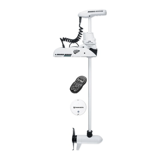
fEATUREs mOTOR fEATUREs Integrated i-Pilot Control Head Power Trim i-PILOT ULTERRA REmOTE Auto Stow/Deploy For complete details on this remote, see page 16 of this manual. Lifetime Warranty Flexible Composite Shaft Trim Up Trim Down Stow/Deploy Weedless Wedge 2 Propeller Cool Quiet Power Motor Specifications subject to change without notice. -
Page 7: Installation
Your new Riptide Ulterra comes out of the box with everything you’ll need for direct to boat mounting. This motor can be direct mounted to the boat or coupled with a Minn Kota quick release bracket for ease of mounting and removal. For compatible quick release mounting brackets and to locate your nearest dealer, visit minnkotamotors.com. - Page 8 InsTALLATIOn Ulterra Installation Guide Parts Included: Description Qty. Screw, 1/4-20 x 2” HH Screw, 1/4-20 x 0.5 HH Washer-Clipped, 1/4”, 1” OD Nut, 1/4-20 Nylock SS Washer, 1/4” Flat 18-8 SS Washer-Mounting, Rubber Tools and Resources Required: • Drill • 5/16”...
- Page 9 For warranty information please visit www.minnkotamotors.com WARNING: This product contains chemicals known to the State of California to cause cancer and birth defects or other reproductive harm. minnkotamotors.com | 9 ©2015 Johnson Outdoors Marine Electronics, Inc. Minn Kota Consumer & Technical Service 121 Power Drive...
-
Page 10: Mounting Options
InsTALLATIOn mOUnTIng OPTIOns The user has the option of stowing with the prop oriented in or out to accommodate diff erent boat cover confi gurations. Follow the procedure below to change prop orientation. Turn power on and deploy motor using the stow/deploy button on the remote (see the Manual Control section or Ulterra Functions for deploying instructions). -
Page 11: Battery & Wiring Installation
CAUTION: These guidelines apply to general rigging to support your Minn Kota motor. Powering multiple motors or additional electrical devices from the same power circuit may impact the recommended conductor gauge and circuit breaker size. If you are using wire longer than that provided with your unit, follow the conductor gauge and circuit breaker sizing table below. -
Page 12: Selecting The Correct Batteries
Breaker Sizing Table” in the previous section to fi nd the appropriate circuit breaker or fuse for your motor. For motors requiring a 60-amp breaker, the Minn Kota MKR-19 60-amp circuit breaker is recommended. COnnECTIng THE bATTERIEs In sERIEs (If REQUIRED fOR YOUR mOTOR) -
Page 13: Motor Wiring Diagram
mOTOR WIRIng DIAgRAm NOTE: This is a universal, multi-voltage diagram. Double-check your motor's voltage for proper connections. Over-Current Protection Devices not shown in this illustration. Control Head Red Slip Ring + Black Slip Ring - Red Trim Motor + Black Trim Motor - Gear Sensor Accessory Trim Module... -
Page 14: Getting Started
gETTIng sTARTED gETTIng sTARTED WITH THE ULTERRA mOTOR mOTOR COnTROL PAnEL POWER On The Ulterra Trolling Motor must be powered “on” manually. The remote will not turn the motor on. The power button is located on the base of the motor. Pressing the power button will turn on Ulterra. The red STATUS light and the green SYSTEM READY light will both be illuminated when powered on. -
Page 15: Getting Started Wit The I-Pilot Remote
gETTIng sTARTED sECTIOn TITLE gETTIng sTARTED gETTIng sTARTED WITH THE i-PILOT REmOTE KnOWIng YOUR REmOTE LAYOUT The i-Pilot remote is divided into four sections: Manual Control, Tracks, Spot-Lock, and Cruise Control/AutoPilot. Buttons in the Manual Control section of the remote do not require a GPS signal to operate and give you full, immediate control over steering, speed and prop functions similar to a CoPilot. - Page 16 gETTIng sTARTED REmOTE COnTROL QUICK REfEREnCE gUIDE TRACKs mAnUAL COnTROL Track to End Navigates to the nearest location Steer Left on a previously recorded track and follows it to its end. Track to Start Navigates to the nearest location Steer Right on a previously recorded track and follows it to its start.
-
Page 17: Knowing Your I-Pilot Controller
gETTIng sTARTED gETTIng sTARTED REmOTE bATTERY REPLACEmEnT 1. Make sure hands are clean, dry and static free. Discharge any static electricity by touching a metal object that is grounded. NOTE: Static electricity can damage the circuit board. 2. With the remote upside down, use a large coin to rotate the battery door counterclockwise until either of the Unlock icons align with the arrow FIGURE A (see Figure B). - Page 18 gETTIng sTARTED gETTIng sTARTED AUDIO mODEs The i-Pilot Controller also contains an internal speaker which can be programmed to work in two diff erent audio modes. The speaker is programmed to operate in audio mode one from the factory. To enable diff erent audio modes hold down at the same time for three seconds.
-
Page 19: System Startup
gETTIng sTARTED gETTIng sTARTED POWER The i-Pilot controller will turn on whenever the trolling motor has power. For Terrova and Riptide ST motors this is when the green system ready light is on. For PowerDrive V2 and Riptide SP motors this is whenever the motor is connected to power. POWER *For this reason it is very important to disconnect a PowerDrive V2 or Riptide SP motor from power when not in use or battery The i-Pilot controller will turn on whenever the trolling motor has power connected and has been turned on. -
Page 20: Manual Control (I-Pilot)
mAnUAL COnTROL mAnUAL COnTROL fUnCTIOnALITY This section describes all Manual Control functions of i-Pilot. A manual function is one in which the operator takes full control of the function such as manually steering the motor in a desired direction or manually adjusting the prop speed to the desired setting, trimming, stowing and deploying, or manually adjusting the prop speed. - Page 21 mAnUAL COnTROL TRImmIng UP AnD DOWn There will be times when you will need to move your motor up or down depending on how your boat is responding. You can trim up to avoid hitting underwater objects and you can trim down if your prop is coming out of the water. Trim the motor up or down with the i-Pilot remote by pressing NOTE: The prop will temporarily stop while trimming the motor and resume once trimming is stopped.
-
Page 22: Gps Motor Control (I-Pilot)
gPs mOTOR COnTROL sECTIOn TITLE UnDERsTAnDIng HOW THE i-PILOT sYsTEm WORKs nAVIgATIOn i-Pilot uses GPS satellite signals as well as digital compass data to know where it is, where it is heading and the direction the motor is pointing. Since i-Pilot depends on GPS satellite signals for navigation, a minimum GPS signal level of one bar is required in order for GPS navigation controls to be enabled. -
Page 23: Spot-Lock
sECTIOn TITLE sPOT-LOCK HOW sPOT-LOCK WORKs sPOT-LOCK Spot-Lock uses a single point as a reference for the spot you want to stay on. This point is recorded and stored into one of the six memory locations when the Spot-Lock button is pushed. Around the Spot-Lock location i-Pilot uses an arrival circle to determine prop speed and direction. - Page 24 sPOT-LOCK sPOT-LOCK sPOT-LOCK EngAgIng sPOT-LOCK EngAgIng sPOT-LOCK 1. Press on the remote. 2. The Memory Location icon will fl ash on the remote LCD for three seconds, allowing you to choose a 1. Press on the remote. memory location by pressing .
-
Page 25: Cruise Control
CRUIsE COnTROL sECTIOn TITLE HOW CRUIsE COnTROL WORKs CRUIsE COnTROL i-Pilot automatically controls the motor speed to maintain a constant GPS speed. EngAgIng CRUIsE COnTROL 1. Press on the remote. 2. The current GPS speed will fl ash, displaying your current speed as the target GPS speed on the remote LCD for three seconds. -
Page 26: Autopilot/Advanced Autopilot
sECTIOn TITLE AUTOPILOT HOW AUTOPILOT WORKs Two diff erent versions of AutoPilot are available: AutoPilot and Advanced AutoPilot. There are distinct diff erences between the two AutoPilots and how they control your boat. AUTOPILOT AutoPilot uses an internal compass to provide heading lock. When AutoPilot is on, it keeps the motor pointed in the same compass direction. -
Page 27: Autopilot/Advanced Autopilot
AUTOPILOT EngAgIng ADVAnCED AUTOPILOT AnD AUTOPILOT 1. To engage Advanced AutoPilot, press once. To engage AutoPilot, press and hold for two seconds. 2. The Advanced AutoPilot or AutoPilot icon will be displayed on the remote LCD. Advanced AutoPilot 3. To adjust desired heading, manually steer motor to new heading. i-Pilot will lock onto new heading. DIsEngAgIng ADVAnCED AUTOPILOT AnD AUTOPILOT will disengage AutoPilot. -
Page 28: Track Recording/Playback
TRACK RECORDIng / PLAYbACK sECTIOn TITLE HOW TRACK RECORDIng AnD PLAYbACK WORK TRACK RECORDIng AnD PLAYbACK When the Track Record button is pressed, i-Pilot starts to record GPS position data in the form of track points. The distance between these points varies based on the speed of the boat and the GPS signal strength. - Page 29 TRACK RECORDIng / PLAYbACK TRACK RECORDIng / PLAYbACK RECORDIng A TRACK 1. Press on the remote. 2. The Memory Location icon will fl ash on the remote LCD for three seconds, allowing you to choose a RECORDIng A TRACK memory location by pressing .
-
Page 30: Track Recording/Playback
TRACK RECORDIng / PLAYbACK REPLAYIng A TRACK (TRACK TO sTART / TRACK TO EnD) 1. Manually navigate the boat to within a quarter mile of the saved track. Due to safety reasons, i-Pilot will not re-engage a saved track greater than a quarter mile away. 2. -
Page 31: Alternative Stowing Procedures
If Ulterra does not reset, repeat the procedure. If the second attempt fails, please contact your local authorized service center or call Minn Kota service at (800) 227-6433. NOTE: If the lower unit of the motor is trimmed within 6 inches of the mounting base and the boat hull is obstructing the motor’s turning radius, manually turn the head of the motor so that the lower unit is perpendicular to the motor ramps prior to beginning this procedure. -
Page 32: Stowing From The Motor
mAnUAL sTOW PROCEDURE In the unlikely event that the motor will not stow from either the remote or foot pedal command, the following alternative stow methods should solve the issue: 1. Trim/Stow Reset Procedure (see “Alternate Stowing Methods” section) 2. Stowing from the Motor (see “Alternate Stowing Methods” section) 3. - Page 33 mAnUAL sTOW PROCEDURE 3. Pull manual trim handle out while lifting up on the trim housing until shaft and trim module can be pulled up by hand. (Figure 17) Figure 17 Figure 17 Trim Housing Trim Housing Trim Handle Trim Handle 4.
-
Page 34: Adjustments
ADjUsTmEnTs ADjUsTIng THE LIfT bELT Periodically slack may appear in the main lift belt, and it may occasionally require small adjustments to maintain belt tension. Using a 5/32” allen wrench turn the socket head cap screw, located on the bottom of the control head, clockwise (see Figure 23) until belt is fi nger tight and you can force fi nger under belt. -
Page 35: Propeller Replacement
sERVICE & mAInTEnAnCE PROPELLER REPLACEmEnT Propeller TOOLS AND RESOURCES REQUIRED: • Box End Wrench - 1/2” for motors with 70 lbs thrust or lower. - 9/16” for motors with 80 lbs thrust or higher. • Screwdriver (optional) Anode/Nut Washer CAUTION: Disconnect the motor from the battery before beginning any prop work or maintenance. -
Page 36: Troubleshooting
TROUbLEsHOOTIng ULTERRA Motor fails to run or lacks power: • Check battery connections for proper polarity. • Are batteries charged? • Make sure terminals and wires are clean and corrosion free. Use fi ne sandpaper or emery cloth to clean terminals. •... - Page 37 TROUbLEsHOOTIng i-PILOT gEnERAL TROUbLEsHOOTIng Problem: The motor is making erratic steering corrections while in AutoPilot, Spot-Lock or Track to Start/End. Solution: Be sure to keep all ferrous metallic objects away from the i-Pilot controller as they will have an impact on the built-in compass.
-
Page 38: Frequently Asked Questions
AUTHORIZED sERVICE CEnTERs Minn Kota has over 300 authorized service centers in the United States and Canada where you can purchase parts or get your products repaired. Please visit our Authorized Service Center page on our website to locate a service center in your area. - Page 39 prop is off . Q: Which quick release brackets are compatible with Ulterra The following quick release brackets can be used with UIterra: MKA-32, MKA-16-02, RTA 17 and RTA 21. Q: Is there a manual Stow and Deploy procedure? Yes. There is a manual method for stowing Ulterra. See the Emergency Stow Procedure section for instructions. Q: When Ulterra is deployed, at what depth does the deploy stop? Ulterra will always deploy to the most recent depth that was used.
- Page 40 No, Spot-Lock and Spot-Lock Recall are fully automatic functions that take full control of motor steering and speed. Q: Where can I purchase additional remotes? Your local Minn Kota retailer should carry additional remotes. Q: If I turn off the remote, will i-Pilot continue to operate? Yes.
-
Page 41: Parts Diagram
80/112 LBS THRUST - 24/36 VOLT - 54”/60”/72” SHAFT This page provides Minn Kota® WEEE compliance disassembly instructions. For more information about where you should dispose of your waste equipment for recycling and recovery and/or your European Union member state requirements, please contact your dealer or distributor from which your product was purchased. -
Page 42: Parts List
PARTs LIsT RIPTIDE ULTERRA 80/112 LBS THRUST - 24/36 VOLT - 54”/60”/72” SHAFT ITEm PART nUmbER DEsCRIPTIOn ITEm PART nUmbER DEsCRIPTIOn 2777030 24 V MOTOR 54" SW 2263011 E-RING 3/8 DIA. SHAFT 2777031 24 V MOTOR 60" SW 2321702 WASHER-FLAT .375 NYLON 2777032 24 V MOTOR 54"... - Page 43 PARTs LIsT RIPTIDE ULTERRA 80/112 LBS THRUST - 24/36 VOLT - 54”/60”/72” SHAFT ITEm PART nUmbER DEsCRIPTIOn ITEm PART nUmbER DEsCRIPTIOn 2202910 STRAIN RLF, HEYCO SR 6N3-4 179† 2776506 STEERING HOUSING ASSY 24 V, SW 2774080 MAIN CONTROL BOARD, 24V, 60", N AMERICA...
- Page 44 PARTs LIsT RIPTIDE ULTERRA 80/112 LBS THRUST - 24/36 VOLT - 54”/60”/72” SHAFT ITEm PART nUmbER DEsCRIPTIOn ITEm PART nUmbER DEsCRIPTIOn 2997824 TRIM HOUSING ASSEMBLY - 60” (EUROPE) 2305402 SHRINK TUBE .374 ID X 2.25" LONG 2997825 TRIM HOUSING ASSEMBLY - 72” (EUROPE)
-
Page 45: Compliance Statements
Minn Kota motors are not subject to the disposal regulations EAG-VO (electric devices directive) that implements the WEEE directive. Nevertheless never dispose of your Minn Kota motor in a garbage bin but at the proper place of collection of your local town council. - Page 46 COmPLIAnCE sTATEmEnTs fCC COmPLIAnCE This device complies with Part 15 of the FCC rules. Operation is subject to the following two conditions: This device may not cause harmful interference. 2. This device must accept any interference that may be received, including interference that may cause undesired operation. Changes or modifi cations not expressly approved by Johnson Outdoors Marine Electronics, Inc.
- Page 47 nOTEs minnkotamotors.com | 47 ©2015 Johnson Outdoors Marine Electronics, Inc.
- Page 48 Stop buying new batteries and start taking care of the ones you’ve got. Many chargers can actually damage your battery over time – creating shorter run times and shorter overall life. Digitally controlled Minn Kota chargers are designed to provide the fastest charge that protect and extend battery life.
Need help?
Do you have a question about the Riptide Ulterra and is the answer not in the manual?
Questions and answers