MINN KOTA ULTERRA Owner's Manual
Bow-mount trolling motor
Hide thumbs
Also See for ULTERRA:
- User manual ,
- Owner's manual (98 pages) ,
- Installation instructions manual (84 pages)
Table of Contents
Advertisement
Advertisement
Table of Contents

Related Manuals for MINN KOTA ULTERRA


Summary of Contents for MINN KOTA ULTERRA
- Page 1 ULTERRA™ BOW-MOUNT TROLLING MOTOR OWNER'S MANUAL...
-
Page 2: Serial Number
Countless hours of research and testing provide you the Minn Kota advantage that can truly take you “Anywhere. Anytime.” We don’t believe in shortcuts. We are Minn Kota. And we are never done helping you catch more fish. -
Page 3: Table Of Contents
Change the Prop Orientation ..................... 26 Adjusting the Lift Belt ........................29 Greasing the Latch Pin and Power Tilt Motor Shaft ............29 Stowing from the Ulterra Motor ....................30 Trim/Stow Reset Procedure ....................... 31 Manually Stowing the Ulterra ......................32 USING THE FOOT PEDAL ...................... -
Page 4: Safety Considerations
WARNING You are responsible for the safe and prudent operation of your vessel. We have designed your Minn Kota product to be an accurate and reliable tool that will enhance boat operation and improve your ability to catch fish. This product does not relieve you from the responsibility for safe operation of your boat. -
Page 5: Warranty
Minn Kota Limited Lifetime Warranty on Composite Shaft JOME warrants to the original retail purchaser only that the composite shaft of the purchaser’s Minn Kota trolling motor will be materially free from defects in materials and workmanship appearing within the original purchaser’s lifetime. JOME will provide a new composite shaft, free of charge, to replace any composite shaft found by JOME to be defective during the term of this warranty. -
Page 6: Know Your Boat
KNOW YOUR BOAT Port Starboard Inboard Outboard Keel Port Starboard Gunwale Transom Stern Gunwale Stern Hull 6 | minnkotamotors.com ©2016 Johnson Outdoors Marine Electronics, Inc. -
Page 7: Features
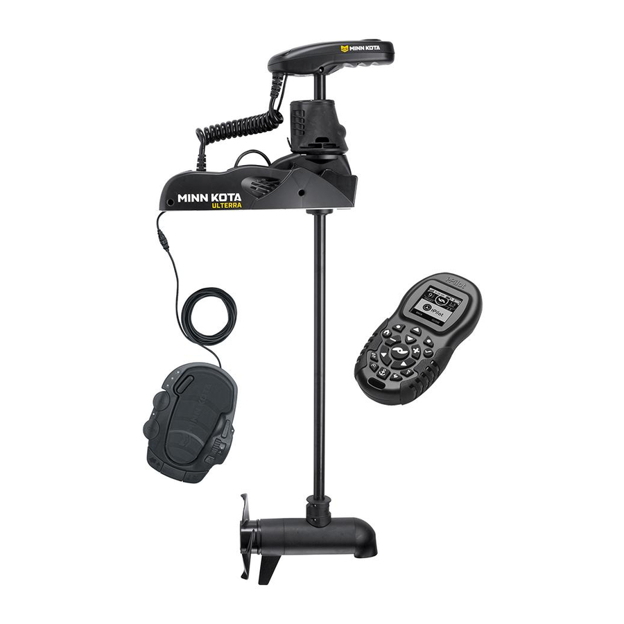
FEATURES Integrated i-Pilot Power Button Control Head Status Indicator System Ready Indicator Power Trim Indicator Panel Motor Mount Auto Stow/Deploy Lifetime Warranty Flexible Composite Shaft Multi-Function Foot Pedal Cool Quiet Power Motor Weedless Wedge 2 Propeller NOTE: Specifications subject to change without notice. This diagram is for reference only and may differ from your actual motor. -
Page 8: Installation
INSTALLING THE ULTERRA Your new Ulterra comes with everything you’ll need to directly install it to the boat. This motor can be directly mounted to the boat or it may be coupled with a Minn Kota quick release bracket for ease of mounting and removal. For installation with a quick release bracket, refer to the installation instructions provided with the bracket. -
Page 9: Installing The Ulterra
INSTALLING THE ULTERRA MOUNTING CONSIDERATIONS It is recommended that the motor be mounted as close to the keel or centerline of View accessories the boat as possible. Make sure the area under the mounting location is clear to drill available for your holes and install nuts and washers. - Page 10 Deck of Boat installation section. NOTE: The Emergency Strap (Item #9) is used for Manually Stowing the Ulterra. The Emergency Keel Strap is not secured during installation. Store it on your boat in the event that you would need to manually stow the motor. To learn how, please refer to the "Manually Stowing the Ulterra"...
- Page 11 INSTALLING THE ULTERRA ITEM(S) NEEDED #8 x 6 WARNING Do not deploy the motor until it is fully mounted to the boat. Illustrations are for reference only. Deploying your motor before it is mounted to the boat may cause injury.
- Page 12 Base Extrusion when installing Nylock Nut are not used when installing the and tightening the motor mounting bolts. Ulterra with a Quick Release Bracket. 12 | minnkotamotors.com ©2016 Johnson Outdoors Marine Electronics, Inc.
- Page 13 Rubber Washer and into place. NOTE: The Short Bolts are not used when installing the Ulterra directly to the boat. p. Slide the Base Extrusion into place under the Bolts that were just installed. q. If installing with a Quick Release Bracket,...
- Page 14 Flat Washer (Item #6) and then securing with Long Bolts a Nylock Nut (Item #7). Clipped Washer NOTE: The Short Bolts are not used when installing the Ulterra directly to the boat. Rubber Washer Flat Washer Nylock Nut Boat Deck Mounting Holes 14 | minnkotamotors.com...
- Page 15 INSTALLING THE ULTERRA v. At this point in the installation process the Motor should be secured to the deck of the boat, and the Motor can now be reassembled. The Extension Damper can be slid back in place on the Damper Pins.
-
Page 16: Routing Universal Sonar & I-Pilot Link Cables
Universal Sonar. If two cables are present, one is to connect the Universal Sonar, and the other is to connect the i-Pilot Link connection. Please follow the Minn Kota recommendations on routing the cables to optimize mobility and maximize functionality. - Page 17 ROUTING UNIvERSAL SONAR & -PILOT LINK CABLES a. Deploy the Motor. Control Head b. Locate the Universal Sonar and/or the i-Pilot Link i-Pilot Link cable(s), at the base of the Control Head. Universal Sonar CAUTION Not following the recommended wire routing for the Coil Cord Universal Sonar and/or i-Pilot Link cable(s), if equipped, may cause damage to the product and void your product...
-
Page 18: Connecting A Universal Sonar Extension Cable
The Universal Sonar Cable may not be long enough to reach the fish finder. If the cable length does not reach the desired fish finder installation location, a 14.5’ extension cable is available. Minn Kota recommends using the MKR-US2-11. a. Deploy the Motor. -
Page 19: Battery & Wiring Installation
CA UTION These guidelines apply to general rigging to support your Minn Kota motor. Powering multiple motors or additional electrical devices from the same power circuit may impact the recommended conductor gauge and circuit breaker size. If you are using wire longer than that provided with your unit, follow the conductor gauge and circuit breaker sizing table below. -
Page 20: Selecting The Correct Batteries
Minn Kota recommends using Minn Kota brand chargers to recharge the batteries connected to your Minn Kota trolling motor, as they have been engineered to work with motors that include a bonding wire. -
Page 21: Connecting The Batteries In Series
CONNECTING THE BATTERIES IN SERIES The negative (-) connection must be connected to the negative terminal of the same battery that the trolling motor negative lead connects to. In the diagrams below this battery is labeled “Low Side” Battery. Connecting to any other trolling motor battery will input positive voltage into the “ground”... - Page 22 CONNECTING THE BATTERIES IN SERIES 36 Volt Systems Three 12 volt batteries are required. The batteries must be wired in series, only as directed in wiring diagram, to provide 36 volts. 1. Make sure that the motor is switched +36 Volts to trolling motor off (speed selector on “0”).
-
Page 23: Motor Wiring Diagram
MOTOR WIRING DIAGRAM ULTERRA WITH i-PILOT OR i-PILOT LINK The following Motor Wiring Diagram applies to all Ulterra models that come factory installed with either i-Pilot or i-Pilot Link. Universal Sonar is an optional feature that may come factory installed. -
Page 24: Using & Adjusting The Motor
Power Button The Ulterra must be powered “on” and “off” manually. The remote will not turn the motor “on” or “off”. The Power button located on the base of the motor on the Indicator Panel. Press the Power button to turn the motor “on”. When the motor is in... - Page 25 The Emergency Strap should be secured every time the motor is manually stowed to prevent damage from high wind, rough water or vibrations, including while the boat is trailered. See the “Manually Stowing the Ulterra” section of the manual for more information on when the Emergency Strap is needed. Belt Collar The Belt Collar holds the lower portion of the Lift Belt in place.
-
Page 26: Change The Prop Orientation
CHANGE THE PROP ORIENTATION MOTOR ADJUSTMENTS Change the Prop Orientation When the motor is mounted onto the boat, the orientation of the Prop may be changed to either Inboard or Outboard to accommodate different boat cover configurations. Complete the following steps to change prop orientation. WARNING When the motor is powered “off”... - Page 27 CHANGE THE PROP ORIENTATION d. Locate the Trim Release Handle on the Side of Trim Housing the Trim Housing. Grasp the Trim Release Handle and pull it out. Trim Release WARNING Handle When using the Trim Handle or moving the Trim Housing, keep fingers clear of all hinges, pivot points and all moving parts above and below the Trim Housing.
- Page 28 CHANGE THE PROP ORIENTATION h. Once in the proper orientation, lower the Trim Trim Housing Housing and Shaft onto the Steering Housing. Trim Release Handle Let the Trim Release Handle move back in place. Trim Housing Shaft Steering Housing Trim Release Handle Reconnect the Power Cables to the battery and make sure the breaker, if equipped, is turned “on”.
-
Page 29: Adjusting The Lift Belt
Greasing the Latch Pin and Power Tilt Motor Shaft In order for the Ulterra to continue running at optimum performance, it is recommended that the Latch Pin and the Motor Shaft for the Power Tilt be greased every season. It is recommended to use a marine grade grease. -
Page 30: Stowing From The Ulterra Motor
Latch Pin Lower Unit Stowing from the Ulterra Motor In the unlikely event your i-Pilot or i-Pilot Link remote becomes non-functioning, you can stow the Ulterra from the base of the motor. a. Locate the Indicator Panel at the base of the Mount. -
Page 31: Trim/Stow Reset Procedure
Trim/Stow Reset Procedure In the unlikely event Ulterra will not trim or stow, the following procedure will reset the motor and restore functionality. If Ulterra does not reset, repeat the procedure. If the second attempt fails, please contact your local authorized service center or call Minn Kota service at (800) 227-6433. -
Page 32: Manually Stowing The Ulterra
1. Trim/Stow Reset Procedure 2. Stowing from the Ulterra Motor 3. If your batteries lose power to the level that the motor will not stow, the motor will most likely stall at a 45 degree angle. - Page 33 MANUALLY STOWING THE ULTERRA b. Using a #2 Phillips Screwdriver, loosen the screw on the Manual Tilt Knob. c. The Manual Tilt Knob holds two Metal Plates together. Using a Flat Blade Screwdriver pry up on the Manual Tilt Knob until it releases from the Metal Plates.
- Page 34 MANUALLY STOWING THE ULTERRA g. While the Trim Housing and Shaft are lifted up, release the Latch Pin Bracket. Trim Housing h. Lift the Trim Housing, Shaft and Lower Unit up, and rotate it. Latch Pin Pull the Lower Unit onto the Mount Ramps.
- Page 35 MANUALLY STOWING THE ULTERRA While the motor is in the stowed position, use a #3 Phillips Screwdriver, to replace the Right Sideplate, if desired. Do this by replacing the two screws that hold the sideplate in place. Screw Right Sideplate Screw minnkotamotors.com | 35...
-
Page 36: Using The Foot Pedal
Indicator Panel will not be illuminated when in Normal Mode. MODE Ulterra Mode When in Ulterra Mode, the buttons at the bottom of the Foot Pedal function to Trim Up, Trim Down, and Stow/Deploy. The amber light on the Indicator Panel will be illuminated during Ulterra Mode. - Page 37 WARNING You are responsible for the safe and prudent operation of your vessel. We have designed Ulterra to be an accurate and reliable tool that will enhance boat operation and improve your ability to catch fish. This product does not relieve you from the responsibility for safe operation of your boat.
- Page 38 Mode is determined by the remote when AutoPilot is initiated from the Foot Pedal. AutoPilot can be used in both Standard and Ulterra Modes. AutoPilot can also be controlled using the remote. For more specific directions on how to use AutoPilot,...
-
Page 39: Stowing And Deploying The Motor With The Foot Pedal
Indicator is on. c. On the Foot Pedal, press the Mode Button until the amber LED in the center of the Indicator Panel on the Foot Pedal is illuminated. This puts the Foot Pedal in Ulterra Mode. AUTOPILOT SPOT-LOCK MODE... -
Page 40: Adjusting The Depth Of The Motor (Trim) With The Foot Pedal
On the Foot Pedal, press the MODE button until the amber LED in the center of the Indicator Panel on the Foot Pedal is illuminated. This puts the Foot Pedal in Ulterra Mode. NOTE: You can only trim your motor while in Ulterra Mode. -
Page 41: Service & Maintenance
SERVICE & MAINTENANCE PROPELLER REPLACEMENT TOOLS AND RESOURCES REQUIRED • 9/16" Open End Wrench • Flat Blade Screwdriver INSTALLATION a. Disconnect the motor from all sources of power prior to changing the propeller. Drive Pin Armature Shaft b. Hold the propeller and loosen the Prop Nut with a pliers or a wrench. -
Page 42: General Maintenance
GENERAL MAINTENANCE GENERAL MAINTENANCE • After use, the entire motor should be rinsed with freshwater. This series of motors is not equipped for saltwater exposure. • The composite shaft requires periodic cleaning and lubrication for proper retraction and deployment. A coating of an aqueous based silicone spray will improve operation. -
Page 43: Frequently Asked Questions
You can reference the parts list located in your manual to identify the specific part numbers. Email Us You can email our consumer service department with questions regarding your Minn Kota products. To email your question, visit minnkotamotors.com and click on “Support”. -
Page 44: Compliance Statements
Minn Kota motors are not subject to the disposal regulations EAG-VO (electric devices directive) that implements the WEEE directive. Nevertheless never dispose of your Minn Kota motor in a garbage bin but at the proper place of collection of your local town council. - Page 45 ENvIRONMENTAL RATINGS Ambient operating temperature range: -10C to 50C Ambient operating humidity range: 5% to 95% Maximum operating altitude: 10,000 feet ULTERRA COMPLIANCE RADIO OPERATION CONTROLLER i-Pilot Equipped Motors • Frequency band: 915 MHz to 921 MHz •...
-
Page 46: Parts Diagram & Parts List
80/112 LBS THRUST - 24/36 VOLT - 45"/60"/72" SHAFT The parts diagram and parts list provides Minn Kota® WEEE compliance disassembly instructions. For more information about where you should dispose of your waste equipment for recycling and recovery and/or your European Union member state requirements, please contact your dealer or distributor from which your product was purchased. - Page 47 SEAL & O-RING KIT *8OLB THRUST* 2881450 SEAL & O-RING KIT 112 *112LB THRUST* 2774162 MOTOR KIT, iPILOT 1.6 ULTERRA *i-PILOT RECEIVER* 2774166 MOTOR KIT, iPILOT 3.0 ULTERRA *i-PILOT LINK RECEIVER* 2994075 REMOTE ASSY, IPILOT 1.6 2994076 REMOTE ASSY, IPILOT LINK *LINK ONLY* Item...
- Page 48 PARTS DIAGRAM & PARTS LIST Item Part # Description Quantity 640-126 LEADWIRE RED 10AWG 71" XLP *4* *80LB THRUST* *60* 640-118 LEADWIRE RED 10 AWG 56 XLP *4* *80LB THRUST* *45* 640-145 LEADWIRE RED 10AWG 75 7/8" GPT *4.5* *112LB THRUST* *60* 640-149 LEADWIRE RED 10AWG 88"...
- Page 49 PARTS DIAGRAM & PARTS LIST Item Part # Description Quantity 582-013 CLIP, RETAINING SHORT *4* *80LB THRUST* 582-016 CLIP-RETAINING, SONAR *4.5* *112LB THRUST* 973-025 SPACER - BRUSHPLATE *4* *80LB THRUST* 990-051 WASHER - STEEL THRUST 990-052 WASHER - NYLATRON 2302104 SCREW-#6-20 X 3/8 THD CUTS,RIE 230-038 CABLE CLAMP...
- Page 50 PARTS DIAGRAM & PARTS LIST Item Part # Description Quantity 2375901 ADAPTER, USB DC POWER LINK 2373241 CABLE, USB REMOTE CHARGER LINK 2211415 CABLE-EXTENSION, PD/AP 110" 2372100 SCREW-#8-18 X 5/8 THD* (SS 2065400 WIRE INSULATOR-LGE 1-3/4,BLUE 2375400 SHRINK TUBE-1/4OD X 1-3/4 2218200 FUSE HOLDER ASSEMBLY 2395520...
- Page 51 PARTS DIAGRAM & PARTS LIST ULTERRA STEERING HOUSING & TRIM HOUSING Steering Housing & Trim Housing Parts Diagram 326 314 minnkotamotors.com | 51 ©2016 Johnson Outdoors Marine Electronics, Inc.
- Page 52 PARTS DIAGRAM & PARTS LIST Steering Housing & Trim Housing Parts List Assembly Part # Description Quantity 2996521 ASM, STEERING 24V *80LB THRUST* 2996522 ASM, STEERING 36V *112 LB THRUST* 2997803 ASSY, T RIM MODULE, FW, 60" 2997820 ASSY, T RIM MODULE, FW, 72" 2997807 ASSY, T RIM MODULE, FW, 45"...
- Page 53 PARTS DIAGRAM & PARTS LIST Item Part # Description Quantity 2321510 COLLAR-DRIVE,BOTTOM 2321704 WASHER-THRUST, STEERING 2321720 SHIM,O-RING 2324608 O-RING,224,PD PRO STR HSG 2327308 BEARING-BALL,SEALED,6809-2RS 2324604 O-RING, CASE SEAL 2308601 BREATHER FILTER, DR.HOUSING 2323408 SCREW-#8-32 X 2.0 SHCS SS 2323410 SCREW-#8-32 X .75 SHCS SS 2202626 PIN-LATCH, SS 2322702...
- Page 54 PARTS DIAGRAM & PARTS LIST Item Part # Description Quantity ✖ SCREW-#4-24 X 1/4 PHCR SS TY B PIN, BELT PULLEY ✖ ✖ PIN, 2' X 1/4" PIN-DOWEL, 1/8" ✖ ✖ BRACKET, DRIVE BLOCK BLOCK, TUBE DRIVE ✖ ✖ GEAR/PULLEY-WORM, CLUSTER ASM ✖...
- Page 55 PARTS DIAGRAM & PARTS LIST Item Part # Description Quantity 2373440 SCREW-#4-24 X 1/4 PHCR SS 2051710 SPLIT LOCK WASHER 3MM 2372103 SCREW-X6 X .375 PLASTITE SS ✖ This part is included in an assembly and cannot be ordered individually. Not shown on Parts Diagram.
- Page 56 PARTS DIAGRAM & PARTS LIST ULTERRA FOOT PEDAL Foot Pedal Parts Diagram 56 | minnkotamotors.com ©2016 Johnson Outdoors Marine Electronics, Inc.
- Page 57 PARTS DIAGRAM & PARTS LIST Foot Pedal Parts List Assembly Part # Description Quantity 2994740 FOOT PEDAL ASSY, ULTERRA 2994859 BAG ASY-TERROVA/V2,RUB.BUMPERS Item Part # Description Quantity 2204500 BASE PLATE-ULTERRA / TERROVA PCB ASSY, ULTERRA ✖ 2373440 SCREW-#4-24 X 1/4 PHCR SS TY B...
- Page 58 PARTS DIAGRAM & PARTS LIST ULTERRA MOUNT Mount Parts Diagram 58 | minnkotamotors.com ©2016 Johnson Outdoors Marine Electronics, Inc.
- Page 59 PARTS DIAGRAM & PARTS LIST Mount Parts List Assembly Part # Description Quantity 2994917 BAG ASSY, ULTERRA MTG HARDWARE 2880350 SENSOR WIRE W/BUTT CONNECTORS 2777900 CAM W/MAGNET, SPRING PIN 2774080 MAIN CTRL BD, US/AU/CA, 24V, 60" *80LB THRUST* *60* 2774081 MAIN CTRL BD, US/AU/CA, 24V, 45"...
- Page 60 PARTS DIAGRAM & PARTS LIST Item Part # Description Quantity 2201722 WASHER-#6, .625 OD, ZP STEEL 2373440 SCREW-#4-24 X 1/4 PHCR SS TY B 2053411 SCREW-#4-40 X 1/4 PPH ZP 2263453 SCREW-1/4-20 X 1" SHCS S/S 2200825 CLIP, SENSOR CABLE 2208800 DAMPER, HYBRID, 80# 2208802...
-
Page 61: Notes
NOTES minnkotamotors.com | 61 ©2016 Johnson Outdoors Marine Electronics, Inc. -
Page 62: Recommended Accessories
Stop buying new batteries and start taking care of the ones you’ve got. Many chargers can actually damage your battery over time – creating shorter run times and shorter overall life. Digitally controlled Minn Kota chargers are designed to provide the fastest charge that protect and extend battery life.
Need help?
Do you have a question about the ULTERRA and is the answer not in the manual?
Questions and answers