Table of Contents
Advertisement
Advertisement
Table of Contents
Troubleshooting

Related Manuals for MINN KOTA RIPTIDE TERROVA 1363707


Summary of Contents for MINN KOTA RIPTIDE TERROVA 1363707
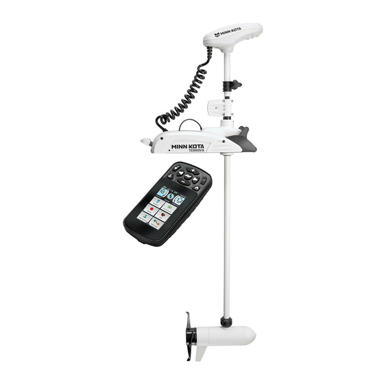
- Page 1 RIPTIDE TERROVA BOW-MOUNT TROLLING MOTOR OWNER'S MANUAL...
-
Page 2: Serial Number
Countless hours of research and testing provide you the Minn Kota advantage that can truly take you “Anywhere. Anytime.” We don’t believe in shortcuts. We are Minn Kota. And we are never done helping you catch more fish. -
Page 3: Table Of Contents
Table of ConTenTs TABLE OF CONTENTS SAFETY CONSIDERATIONS .....................4 WARRANTY ............................5 KNOW YOUR BOAT ........................6 FEATURES ............................7 INSTALLATION ..........................8 Installing the Riptide Terrova ......................9 Routing the i-Pilot Link Cable ..................... 13 BATTERY & WIRING INSTALLATION ................15 Boat Rigging & Product Installation ..................15 Conductor Gauge and Circuit Breaker Sizing Table.............. -
Page 4: Safety Considerations
WARNING You are responsible for the safe and prudent operation of your vessel. We have designed your Minn Kota product to be an accurate and reliable tool that will enhance boat operation and improve your ability to catch fish. This product does not relieve you from the responsibility for safe operation of your boat. -
Page 5: Warranty
Minn Kota Limited Lifetime Warranty on Composite Shaft JOME warrants to the original retail purchaser only that the composite shaft of the purchaser’s Minn Kota trolling motor will be materially free from defects in materials and workmanship appearing within the original purchaser’s lifetime. JOME will provide a new composite shaft, free of charge, to replace any composite shaft found by JOME to be defective during the term of this warranty. -
Page 6: Know Your Boat
KNOW YOUR BOAT Port Starboard Inboard Outboard Keel Port Starboard Gunwale Transom Stern Gunwale Stern Hull ©2016 Johnson Outdoors Marine Electronics, Inc. -
Page 7: Features
FEATURES AutoPilot Push-to-Test Power Battery Meter POWER AUTOPILOT BATTERY METER Power TEST WITH MOTOR OFF Adjustable Depth Collar TEST Button Depth Collar Knob Indicator Panel Lift Assist Housing Steering Housing Stow Deploy Lever Fall Away Ramps Lifetime Warranty Flexible Composite Shaft Lift Assist Collar Cool Quiet Power... -
Page 8: Installation
Your new RiptideTerrova comes with everything you’ll need to directly install it to the boat. This motor can be directly mounted to the boat or coupled with a Minn Kota quick release bracket for ease of mounting and removal. For installation with a quick release bracket, refer to the installation instructions provided with the bracket. -
Page 9: Installing The Riptide Terrova
INSTALLING THE RIPTIDE TERROVA MOUNTING CONSIDERATIONS It is recommended that the motor be mounted as close to the centerline of the boat as possible. Make sure the area under the mounting location is clear to drill holes and install nuts and washers. Make sure the motor rest is positioned far enough beyond the edge of the boat. - Page 10 INSTALLING THE RIPTIDE TERROVA c. Remove the Right Sideplate. d. Swing the Left Sideplate out and away from the Base Extrusion. Base Extrusion Left Sideplate Right Sideplate e. Make sure that the Power Cables from the battery are disconnected, or that the breaker, Power Cables if equipped, is "off".
- Page 11 INSTALLING THE RIPTIDE TERROVA ITEM(S) NEEDED #4 x 6 g. When the motor is in the deployed position, make sure that the Shaft is 1-1/2" out past the Gunwale of the boat. The lower unit, when stowed and deployed must not encounter any obstructions. h.
- Page 12 INSTALLING THE RIPTIDE TERROVA ITEM(S) NEEDED #1 x 6 #2 x 6 #3 x 6 #4 x 6 k. Put a 1/4-20 x 3 1/2" (Item #1) screw in each Screw of the drilled locations. The screw should pass through the Base Extrusion and the boat deck. If the rubber washers (Item #4) are used, they should sit between the Base Extrusion and boat deck.
-
Page 13: Routing The I-Pilot Link Cable
Link system. If no connections are present, your motor may or may not be installed with i-Pilot. Please follow the Minn Kota recommendations on routing the cables to optimize mobility and maximize functionality. - Page 14 ROUTING THE -PILOT LINK CABLE a. Place the motor in the deployed position. Control Head b. Locate the i-Pilot Link cable, at the base of the Control Head. i-Pilot Link CAUTION Not following the recommended wire routing for the Coil Cord i-Pilot Link cable, if equipped, may cause damage to the product and void your product warranty.
-
Page 15: Battery & Wiring Installation
CA UTION These guidelines apply to general rigging to support your Minn Kota motor. Powering multiple motors or additional electrical devices from the same power circuit may impact the recommended conductor gauge and circuit breaker size. If you are using wire longer than that provided with your unit, follow the conductor gauge and circuit breaker sizing table below. -
Page 16: Selecting The Correct Batteries
Minn Kota recommends using Minn Kota brand chargers to recharge the batteries connected to your Minn Kota trolling motor, as they have been engineered to work with motors that include a bonding wire. -
Page 17: Connecting The Batteries
CONNECTING THE BATTERIES IN SERIES The negative (-) connection must be connected to the negative terminal of the same battery that the trolling motor negative lead connects to. In the diagrams below this battery is labeled “Low Side” Battery. Connecting to any other trolling motor battery will input positive voltage into the “ground”... -
Page 18: Connecting The Batteries In A Series
CONNECTING THE BATTERIES IN SERIES 36 Volt Systems CONNECTING THE BATTERIES IN SERIES CONNECTING THE BATTERIES IN SERIES Three 12 volt batteries are required. The batteries must be wired in series, only as directed in wiring diagram, to provide 36 (IF REQUIRED FOR YOUR MOTOR) (IF REQUIRED FOR YOUR MOTOR) volts. - Page 19 CONNECTING THE BATTERIES IN SERIES 36 Volt Systems Three 12 volt batteries are required. The batteries must be wired in series, only as directed in wiring diagram, to provide 36 volts. 1. Make sure that the motor is switched +36 Volts to trolling motor off (speed selector on “0”).
-
Page 20: Motor Wiring Diagram
Motor Wiring DiagraM RIPTIDE TERROVA The following Motor Wiring Diagram applies to all RiptideTerrova models that do not come factory installed with i-Pilot or i-Pilot Link. CoPilot may come factory installed, but can also be installed as an after market accessory. A Foot Pedal can be installed as an after market accessory. - Page 21 MOTOR WIRING DIAGRAM RIPTIDE TERROVA WITH i-PILOT OR i-PILOT LINK The following Motor Wiring Diagram applies to all Riptide Terrova models that come factory installed with either i-Pilot or i-Pilot Link. A Foot Pedal can be installed as an after market accessory. i-Pilot Black M- Black B-...
-
Page 22: Using & Adjusting The Motor
USING & ADJUSTING THE MOTOR MOUNT FEATURES Become familiar with the features of the motor to maximize the capabilities this product offers. Depth Collar Knob Steering Housing Lift Assist Collar Lower Unit Lift Assist Housing Depth Collar Shaft Fall Away Ramp AutoPilot Power POWER AUTOPILOT... -
Page 23: Stowing And Deploying The Motor
ADjUSTING THE DEPTH OF THE MOTOR CAUTION For safety reasons, disconnect the motor from the battery/batteries when the motor is not in use or while the battery/batteries are being charged. If the motor control is left on and the propeller rotation is blocked, severe motor damage can result. AutoPilot The AutoPilot Indicator is located on the Indicator Panel on the Mount. -
Page 24: Push-To-Test Battery Meter
ADjUSTING THE DEPTH OF THE MOTOR PUSH-TO-TEST BATTERY METER This motor is equipped with a Pust-to-Test Battery Meter. Push-to-Test Indicator Battery Meter The LED located on the Indicator Panel on the Mount of the POWER AUTOPILOT Panel motor. The Battery Meter provides an accurate display of the BATTERY METER TEST WITH MOTOR OFF remaining charge in the battery. -
Page 25: Adjusting The Depth Of The Motor
ADjUSTING THE DEPTH OF THE MOTOR MOTOR ADjUSTMENTS Adjusting the Depth of the Motor Once the boat is on the water, it may be necessary to adjust the Lower Unit up or down to achieve an optimum depth for motor performance. -
Page 26: Adjusting The Lower Unit For A Secure Stow
ADjUSTING THE LATCH COLLAR Adjusting the Lower Unit for a Secure Stow When the Motor is stowed, the Lower Unit should rest on the Fall Away Ramps, a part of the Motor Mount. It is recommended to secure the motor using the following instructions to avoid damage to the motor and shaft from vibrations during transport. a. -
Page 27: Installing An External Transducer
INSTALLING AN ExTERNAL TRANSDUCER Installing an External Transducer Your trolling motor may be pre-installed with a Universal Sonar transducer system. An external transducer is not included with your trolling motor. An external transducer can be installed onto the motor. a. Mount the External Transducer according to directions provided with the transducer. -
Page 28: Copilot
COPILOT CONTROLLING THE MOTOR WITH COPILOT Review the complete CoPilot section of this manual to become familiar with this feature. High Speed Bypass Decrease Speed AutoPilot ON/OFF Steer Left Increase Speed Prop ON/OFF Steer Right Prop ON/OFF This button is located in the middle of the remote. It turns the propeller on or off. Press the button once to turn the propeller ON; press button a second time to turn it OFF. -
Page 29: Copilot General Operation
COPILOT COPILOT GENERAL OPERATION Operating with the Remote and Foot Pedal • The CoPilot and foot pedal can be used for motor control simultaneously. • The foot pedal and CoPilot remote operate on a first-in-line priority basis. If a button is pressed and held down on the foot pedal and a button with the same function is then pressed on the remote, the foot pedal will have priority. -
Page 30: Audio Modes
COPILOT AUDIO MODES There are three receiver Audio Modes available. The unit is factory set to Audio Mode 2. To switch from one audio mode to another, simultaneously press and hold the increase and decrease speed buttons for one second. The receiver will respond with 1, 2 or 3 audible beeps indicating the corresponding receiver audio mode change. -
Page 31: Adding/Removing Remotes
COPILOT ADDING/REMOVING REMOTES The CoPilot remote came from the factory already "Learned" by the CoPilot receiver. Any additional remotes must be "Learned" by the receiver. The receiver stores all "Learned" information even when the motor is disconnected from a power source. To "Learn"... -
Page 32: Replacing The Battery
COPILOT b. Press and hold the Learn Button and power up the CoPilot receiver by reconnecting the Power Cables, or by making sure that the breaker, if equipped, is "on". c. Continue to hold the Learn Button down for 10 seconds. - Page 33 COPILOT d. Reassemble the remote. Begin by removing the board from the front of the remote case. This is Remote the same board that holds the battery. Leave the Case Front Keypad in place on the front of the remote. e.
-
Page 34: Service & Maintenance
SERVICE & MAINTENANCE PROPELLER REPLACEMENT TOOLS AND RESOURCES REQUIRED • 9/16” Open End Wrench • Flat Blade Screwdriver INSTALLATION a. Disconnect the motor from all sources of power prior to changing the propeller. Drive Pin Armature Shaft b. Hold the propeller and loosen the Prop Nut with a pliers or a wrench. -
Page 35: General Maintenance
SERVICE & MAINTAINANCE GENERAL MAINTENANCE • After every use, the entire motor should be rinsed with freshwater, then wiped down with a cloth dampened with an aqueous based silicone spray. Do not spray water into the ventilation openings in the head of the motor. •... -
Page 36: Troubleshooting The Copilot
SERVICE & MAINTAINANCE TROUBLESHOOTING THE COPILOT Cause Effect Solution The battery is discharged. Replace battery. Receiver may not have "learned" the remote. Remote needs to be learned. See the Adding/ Removing Remotes section of this manual to learn the remote. With the foot pedal connected, the MOM-CON The foot pedal switch must be placed in Momentary Remote is not transmitting. -
Page 37: Compliance Statements
Minn Kota motors are not subject to the disposal regulations EAG-VO (electric devices directive) that implements the WEEE directive. Nevertheless never dispose of your Minn Kota motor in a garbage bin but at the proper place of collection of your local town council. - Page 38 Model: CoPilot This is only applicable to motors factory installed with CoPilot • Contains IC: 4397A-M05COPLT • Contains FCC ID: M05COPLT FCC COMPLIANCE This device complies with Part 15 of the FCC rules. Operation is subject to the following two conditions: This device may not cause harmful interference.
-
Page 39: Parts Diagram & Parts List
55/80/112 LBS THRUST - 12/24/36 VOLT - 54”/60”/72" SHAFT The parts diagram and parts list provides Minn Kota® WEEE compliance disassembly instructions. For more information about where you should dispose of your waste equipment for recycling and recovery and/or your European Union member state requirements, please contact your dealer or distributor from which your product was purchased. - Page 40 PARTS DIAGRAM & PARTS LIST Motor Parts List Assembly Part # Description Quantity 2779034 MTR/TUBE ASM 55# 54" RT TRV BT *MOTOR & TUBE* *54* *3.625* 2777034 MTR/TUBE ASM 80# 54" TRV BT *MOTOR & TUBE* *54* *4* 2777083 MTR/TUBE 112# 60" RT TRV BT *MOTOR & TUBE* *60* *4.5* 2777036 MTR/TUBE ASM 80# 60"...
- Page 41 PARTS DIAGRAM & PARTS LIST Item Part # Description Quantity 2256300 TIE WRAP-5.5" BLACK 2260906 KNOB-SOFT GRIP,HG/DR,SS 2292501 CONTROL BOX, SW ST 2332102 SCREW-#10-24 X 1-3/4 PPH SS 2333101 NUT-HEX #10-24 UNC-2B NYL SS 2224705 INSERT-PLUG, WHT, I PILOT*SMALL HOLE* *i-PILOT* 2224703 INSERT-PLUG, PD/AP WHITE *NO HOLE* ✖...
- Page 42 PARTS DIAGRAM & PARTS LIST Item Part # Description Quantity 640-049 LEADWIRE BLK 10AWG 88.50" GPT 640-023 LEADWIRE BLK 10 AWG 69" GPT 640-045 LEADWIRE BLK 10 AWG 76.5 GPT 640-025 LEADWIRE BLK 10 AWG 66 3/4 XLP 640-022 LEADWIRE BLK 10 AWG 72.5 XLP ✖...
- Page 43 PARTS DIAGRAM & PARTS LIST Item Part # Description Quantity 830-027 SCREW - SELF-THREAD 10-32X2.25 *80LB THRUST* *4.0* 2053410 SCREW-#8-32 X 1/2 TRI-LOBE HEX *112LB THRUST* *4.5* 830-008 THRU BOLT 10-32 x 9.205 *55LB THRUST* *3.625* 830-094 THRU BOLT 12-24 X10.31 *80LB THRUST* *4.0* *112LB THRUST* *4.5* 830-094 THRU BOLT 12-24 x 10.31 *80LB THRUST* *4.0* 990-067...
- Page 44 PARTS DIAGRAM & PARTS LIST RIPTIDE TERROVA STEERING HOUSING Steering Housing Parts Diagram WW XX 44 | ©2016 Johnson Outdoors Marine Electronics, Inc.
- Page 45 PARTS DIAGRAM & PARTS LIST Steering Housing Parts List Assembly Part # Desctiption Quantity STEERING HSG ASM 12V SW 2997064 STEERING HSG ASM 24V SW 2997065 STEERING HSG ASM 36V SW 2997063 LIFT ASSIST, 55# SW 2992730 LIFT ASSIST, 80# SW 2992731 LIFT ASSIST, 112# SW 2992732...
- Page 46 PARTS DIAGRAM & PARTS LIST Item Part # Desctiption Quantity 2321510 COLLAR-DRIVE,BOTTOM 2321720 SHIM,O-RING 2324608 O-RING,224, STR HSG 2321530 LINER OUTPUT TUBE, LIFT ASSIST 2324604 O-RING, CASE SEAL ✖ HOUSING-STEERING, TOP, SW 2323408 SCREW-#8-32 X 2.0 SHCS SS 2322601 PIN-LATCH, SS 2321702 WASHER-FLAT .375 NYLON 2263011...
- Page 47 PARTS DIAGRAM & PARTS LIST RIPTIDE TERROVA MOUNT Mount Parts Diagram 498 538 548 | 47 ©2016 Johnson Outdoors Marine Electronics, Inc.
- Page 48 PARTS DIAGRAM & PARTS LIST Mount Parts List Assembly Part # Desctiption Quantity 2774066 CTRL BRD, 24/36V TRV BT w/SHRNK 2774067 CTRL BRD, 12V TRV BT w/SHRNK *i-PILOT/i-PILOT LINK* 2774069 CTRL, BRD, 24/36V IP TRV BT, SHRNK *i-PILOT/i-PILOT LINK* 2994864 BAG ASSY-TERROVA/V2,MNTG HDW Item Part #...
- Page 49 PARTS DIAGRAM & PARTS LIST Item Part # Desctiption Quantity 2322716 SPRING, EXTENSION, T2 2321700 WASHER #10 SS 2323422 SCREW-#10-24 X .25" PPH SS MCH 2322921 STAND-OFF, ALUM. ANODIZED 2321927 PLATE-SKID, LEFT 2323403 SCREW-1/4-20 X.375 MCH SS CRPH 2320218 COVER, HANDLE COSMETIC SW 2383446 SCREW-#8-16 X .50"...
- Page 50 PARTS DIAGRAM & PARTS LIST Item Part # Description Quantity 2301720 WASHER-MOUNTING - RUBBER 2305410 SHRINK TUBE-.315 OD X 2.25" *SALTWATER* 2305415 SHRINK TUBE-.472 ID X 2.25" *SALTWATER* 2305403 SHRINK TUBE-.500 IDX1.0" ADHSV *SALTWATER* 2332104 SCREW-1/4-20 X 5/8 S/S 2323402 SCREW-1/4-20 X .375 T-L, ZP ✖...
-
Page 51: Notes
Stop buying new batteries and start taking care of the ones you’ve got. Many chargers can actually damage your battery over time – creating shorter run times and shorter overall life. Digitally controlled Minn Kota chargers are designed to provide the fastest charge that protect and extend battery life.
Need help?
Do you have a question about the RIPTIDE TERROVA 1363707 and is the answer not in the manual?
Questions and answers