MINN KOTA ULTERRA Owner's Manual
Bow-mount trolling motor
Hide thumbs
Also See for ULTERRA:
- User manual ,
- Owner's manual (98 pages) ,
- Installation instructions manual (84 pages)
Advertisement
Quick Links
Advertisement

Related Manuals for MINN KOTA ULTERRA


Summary of Contents for MINN KOTA ULTERRA
- Page 1 ULTERRA™ BOW-MOUNT TROLLING MOTOR Owner's Manual...
- Page 2 Thank you for choosing Minn Kota. We believe that you should spend more time fishing and less time positioning your boat. That’s why we build the smartest, toughest, most intuitive trolling motors on the water. Every aspect of a Minn Kota trolling motor is thought out and rethought until it’s good enough to bear our name.
- Page 3 Changing the Prop Orientation ..................44 Adjusting the Lift Belt ....................47 Greasing the Latch Pin and Power Tilt Motor Shaft ............47 Stowing from the Ulterra Motor ................... 48 Trim/Stow Reset Procedure ..................49 Manually Stowing the Ulterra ..................50 ADVANCED GPS NAVIGATION WIRELESS REMOTE ................
- Page 4 WARNING You are responsible for the safe and prudent operation of your vessel. We have designed your Minn Kota product to be an accurate and reliable tool that will enhance boat operation and improve your ability to catch fish. This product does not relieve you from the responsibility for safe operation of your boat.
- Page 5 Minn Kota Limited Two-Year Warranty on the Entire Product JOME warrants to the original retail purchaser only that the purchaser’s new Minn Kota freshwater trolling motor will be materially free from defects in materials and workmanship appearing within two (2) years after the date of purchase. JOME will (at its option) either repair or replace, free of charge, any parts found by JOME to be defective during the term of this warranty.
- Page 6 KNOW YOUR BOAT Starboard Starboard Port Port Inboard Inboard Outboard Outboard Keel Keel Port Port Starboard Starboard Gunwale Gunwale Transom Transom Stern Stern Gunwale Gunwale Stern Stern Hull Hull 6 | minnkotamotors.com ©2023 Johnson Outdoors Marine Electronics, Inc.
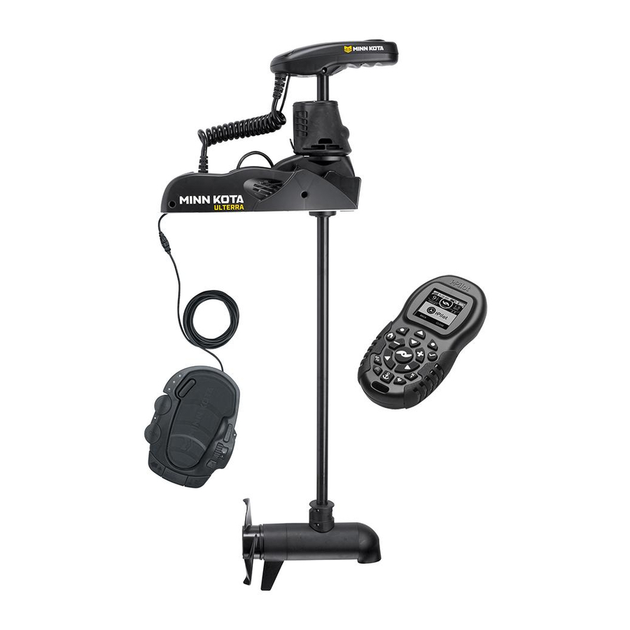
- Page 7 Advanced GPS Navigation Navigation Power Button Power Button Status Status Indicator Indicator System Ready Indicator System Ready Indicator ULTERRA Indicator Panel Indicator Panel Power Trim Power Trim Motor Mount Motor Mount Auto Stow/Deploy Auto Stow/Deploy Lifetime Warranty Lifetime Warranty Flexible Composite Shaft...
- Page 8 INSTALLING THE ULTERRA Your new Ulterra comes with everything you’ll need to directly install it to the boat. This motor can be directly mounted to the boat or it may be coupled with a Minn Kota quick release bracket for ease of mounting and removal. For installation with a quick release bracket, refer to the installation instructions provided with the bracket.
- Page 9 Screw Screw Screw Screw Screw Screw NOTICE: This motor weighs approximately 70 lbs. Minn Kota recommends having a second person help with Stowed Stowed Deployed Deployed the installation. Remove the Right Sideplate to access the Mounting Slots. Remove the Left Sideplate to access the Mounting Holes.
- Page 10 Deck of Boat NOTICE: The Emergency Strap (Item #9) is used for manually stowing the Ulterra. The Emergency Strap is not secured during installation. Store it on your boat in the event that you would need to manually stow the motor.
- Page 11 INSTALLING THE ULTERRA ITEM(S) NEEDED #8 x 6 WARNING Failure to allow 1-1/2" of clearance for the Shaft NOTICE: when mounting may cause failures when the motor stows and deploys. Follow recommended mounting considerations Illustrations are for reference only. Do not deploy the motor to avoid obstructions when operating the motor.
- Page 12 NOTICE: The Short Bolts (Item #4) are only used when installing the Ulterra to a quick release bracket. If installing the Ulterra to a quick release bracket, please refer to the instructions that came with the bracket for more information. Quick release bracket installation instructions can also be viewed online at minnkotamotors.com.
- Page 13 NOTICE: The Short Bolts (Item #4) are only used Washer Washer when installing the Ulterra to a quick release bracket. If installing the Ulterra to a quick release Mounting Mounting Holes Holes bracket, please refer to the instructions that came...
- Page 14 INSTALLING THE ULTERRA At this point in the installation process, the Motor should be secured to the deck of the boat and can now be reassembled. The Extension Damper can be slid back in place on the Damper Pins. This should...
- Page 15 Feature & Cable Identification The Ulterra is pre-installed with Advanced GPS Navigation - including the ability to connect via Ethernet to a Humminbird unit. It is also installed with sonar, either Dual Spectrum CHIRP or Built-in MEGA Down Imaging. Dual Spectrum CHIRP and Built-in MEGA Down Imaging will be installed in combination with Advanced GPS Navigation.
- Page 16 CRITICAL CABLE ROUTING Dual Spectrum CHIRP or Built-in MEGA Down Imaging is Dual Spectrum CHIRP Built-in MEGA Down Imaging pre-installed on your trolling motor. One Sonar Accessory Cable will exit the base of the Control Head and run down the center of the Coil Cord.
- Page 17 FEATURE & CABLE MANAGEMENT Feature & Cable Management DUAL SPECTRUM CHIRP Your trolling motor may be pre-installed with a transducer system Dual Spectrum CHIRP featuring Humminbird’s Dual Spectrum CHIRP. CHIRP stands for “Compressed High Intensity Radar Pulse”. Dual Spectrum CHIRP is a 2D sonar transducer with a temperature sensor that is integrated into the lower unit of the trolling motor.
- Page 18 DUAL SPECTRUM CHIRP The integrated design of the Dual Spectrum CHIRP transducer protects it in the lower unit of the trolling motor from underwater hazards and prevents tangles and damage to the transducer cables. In certain situations, air bubbles may adhere to the surface of the Dual Spectrum CHIRP transducer and a ect the performance.
- Page 19 If using cable ties, do not over-tighten. Any excess cable should be bundled in a loose loop of no less than 4” in diameter. The connection cable should be routed to the fish finder following Minn Kota recommendations on routing the cables to optimize mobility and maximize functionality.
- Page 20 DUAL SPECTRUM CHIRP Verify the length of your motor shaft to determine if 60" Shaft 45" Shaft Advanced GPS Advanced GPS Critical Cable Routing applies to your trolling motor. Navigation Navigation If the trolling motor shaft is 60 inches long, adjust Advanced GPS Advanced GPS the Dual Spectrum CHIRP Cable to exit the Coil...
- Page 21 BUILT-IN MEGA DOWN IMAGING ITEM(S) NEEDED #22 or 23 x 1 If installing directly to a Helix Adapter Cable, align Fourteen Pin Fourteen Pin Receptacle Receptacle the pins on the accessory cable or extension cable Connector Connector with the receptacle on the Helix Adapter Cable (Item #22 or 23).
- Page 22 BUILT-IN MEGA DOWN IMAGING Considerations for Connecting and Routing Built-in MEGA Down Imaging If Built-in MEGA Down Imaging is pre-installed on your trolling motor, one Built-in MEGA Down Imaging accessory cable will exit the base of the Control Head and run down the center of the Coil Cord. Built-in MEGA Down Imaging requires cables to be connected to an output device such as a Humminbird®...
- Page 23 BUILT-IN MEGA DOWN IMAGING CAUTION Failure to follow the recommended wire routing for installed features, if equipped, may cause damage to the product and void your product warranty. Route cables away from pinch points or other areas that may cause them to bend in sharp angles. Routing the cables in any way other than directed may cause damage to the cables by being pinched or severed.
- Page 24 BUILT-IN MEGA DOWN IMAGING Verify the length of your motor shaft to determine 60" Shaft 45" Shaft Advanced GPS Advanced GPS if Critical Cable Routing applies to your trolling Navigation Navigation motor. If the trolling motor shaft is 60 inches long, Advanced GPS Advanced GPS adjust the Built-in MEGA Down Imaging Cable to...
- Page 25 BUILT-IN MEGA DOWN IMAGING ITEM(S) NEEDED #22 or 23 x 1 If installing directly to a Helix Adapter Cable, align Fourteen Pin Fourteen Pin Receptacle Receptacle the pins on the accessory cable or extension cable Connector Connector with the receptacle on the Helix Adapter Cable (Item #22 or 23).
- Page 26 ADVANCED GPS NAVIGATION Your Minn Kota trolling motor and Humminbird fish finder communicate with each other to change the way you fish. Advanced GPS Navigation o ers a large array of features including controlling speed, steering, Spot-Lock, and the ability to record and retrace paths on the water, all at your fingertips.
- Page 27 Head next to the Coil Cord. Coil Coil Cord Cord NOTICE: Ulterra trolling motors with Advanced GPS Navigation are also equipped with Sonar. Sonar is pre-installed from the factory and may be either Dual Power Power Spectrum CHIRP or Built-in MEGA Down Imaging. A...
- Page 28 ADVANCED GPS NAVIGATION ITEM(S) NEEDED #15 x 1 Identify the keyed Receptacle on the Ethernet Control Head Control Head Advanced GPS Advanced GPS Cable (Item #15). It will be keyed to fit with the Eight Ethernet Ethernet Advanced GPS Advanced GPS Pin Advanced GPS Ethernet Connector below the Connector Connector...
- Page 29 ADVANCED GPS NAVIGATION Take the Sonar Cable and unwind it from the inside Control Head Control Head of the Coil Cord, working from the Mount towards the Control Head. Once loose, the Sonar Cable will Advanced GPS Advanced GPS run parallel to the Coil Cord, but hang freely. Once Ethernet Connector Ethernet Connector all cables are connected, the final installation will...
- Page 30 Cable Cable Cable to secure the connection. Helix Adapter Cable Helix Adapter Cable NOTICE: Minn Kota provides one Helix Adapter Cable (AS EC QDE - Ethernet Adapter Cable - 720074-1) with every trolling motor equipped with Advanced GPS Navigation. Ethernet...
Need help?
Do you have a question about the ULTERRA and is the answer not in the manual?
Questions and answers