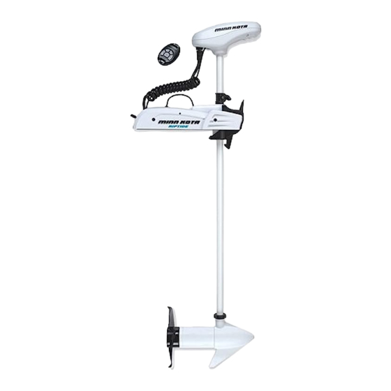
MINN KOTA RIPTIDE POWERDRIVE Owner's Manual
Bow-mount trolling motor
Hide thumbs
Also See for RIPTIDE POWERDRIVE:
- Owner's manual (88 pages) ,
- Installation instructions manual (53 pages) ,
- Owner's manual (104 pages)
Table of Contents
Advertisement
Quick Links
Advertisement
Table of Contents
Troubleshooting

Related Manuals for MINN KOTA RIPTIDE POWERDRIVE


Summary of Contents for MINN KOTA RIPTIDE POWERDRIVE
- Page 1 RIPTIDE POWERDRIVE BOW-MOUNT TROLLING MOTOR Owner's Manual...
- Page 2 Countless hours of research and testing provide you the Minn Kota advantage that can truly take you “Anywhere. Anytime.” We don’t believe in shortcuts. We are Minn Kota. And we are never done helping you catch more fish.
-
Page 3: Table Of Contents
WARRANTY ..........................5 KNOW YOUR BOAT ........................6 FEATURES ..........................7 INSTALLATION ........................8 Installing the Riptide PowerDrive ..................9 Installing the Prop ......................14 Identifying Trolling Motor Features and their Associated Cables ........15 Advanced GPS Navigation ..................... 16 Securing Connection Cables .................. -
Page 4: Safety Considerations
WARNING You are responsible for the safe and prudent operation of your vessel. We have designed your Minn Kota product to be an accurate and reliable tool that will enhance boat operation and improve your ability to catch fish. This product does not relieve you from the responsibility for safe operation of your boat. -
Page 5: Warranty
Minn Kota Limited Two-Year Warranty on the Entire Product JOME warrants to the original retail purchaser only that the purchaser’s new Minn Kota saltwater trolling motor will be materially free from defects in materials and workmanship appearing within two (2) years after the date of purchase. JOME will (at its option) either repair or replace, free of charge, any parts found by JOME to be defective during the term of this warranty. -
Page 6: Know Your Boat
KNOW YOUR BOAT Port Starboard Inboard Outboard Keel Port Starboard Gunwale Transom Stern Gunwale Stern Hull 6 | minnkotamotors.com ©2023 Johnson Outdoors Marine Electronics, Inc. -
Page 7: Features
FEATURES Advanced GPS Navigation Indicator Panel Depth Collar Knob Push-to-Test Battery Adjustable Meter Depth Collar Steering Housing Tilt Lock Lever Deploy-Assist Lever Lifetime Warranty Flexible Composite Shaft Latch Collar Cool Quiet Power Motor Propeller NOTICE: Specifications subject to change without notice. This diagram is for reference only and may differ from your actual motor. minnkotamotors.com | 7 ©2023 Johnson Outdoors Marine Electronics, Inc. -
Page 8: Installation
Your new Riptide PowerDrive comes with everything you’ll need to directly install it to the boat. This motor can be directly mounted to the boat or coupled with a Minn Kota quick release bracket for ease of mounting and removal. For installation with a quick release bracket, refer to the installation instructions provided with the bracket. -
Page 9: Installing The Riptide Powerdrive
PowerDrive is "on". When the Power Cables are disconnected from the battery, the Riptide PowerDrive is "off". If the Power Cables are connected to a breaker, the Riptide PowerDrive is "on" when the breaker is "on" and "off" when the breaker is "off". - Page 10 INSTALLING THE RIPTIDE POWERDRIVE Place the mount on an elevated, level surface such as a workbench or the tailgate of a pickup. The motor, as removed from the box, should be in the Stowed Stowed Deployed Deployed stowed position. Remove the four sideplate screws using a #3 or #2 Phillips screwdriver.
- Page 11 INSTALLING THE RIPTIDE POWERDRIVE Place the mount as close to the centerline or keel of the boat as possible. The motor can be installed on either the Port or Starboard side of the boat based on personal preference. Check placement with the motor in the stowed and deployed positions.
- Page 12 INSTALLING THE RIPTIDE POWERDRIVE ITEM(S) NEEDED #4 x 6 #1 x 6 Put a 1/4-20 x 3-1/2" (Item #1) Mounting Bolt in each of the drilled locations. The Mounting Bolt Mounting Bolt should pass through the Base Extrusion and the boat deck.
- Page 13 INSTALLING THE RIPTIDE POWERDRIVE m. Replace the Right Sideplate. Swing the Left Sideplate back into its correct position on the Base Extrusion. Base Extrusion Base Extrusion Left Left Right Sideplate Right Sideplate Sideplate Sideplate Replace the four Sideplate Screws using a #3 or #2 Phillips screwdriver.
-
Page 14: Installing The Prop
INSTALLING THE PROP Installing the Prop CAUTION Prop Prop Washer Washer Drive Drive Disconnect the motor from the battery before Prop Prop beginning any prop work or maintenance. While holding the Shipping Spacer with a pliers or vise grip, remove the Prop Nut, Red Shipping Washer, Prop Washer and Spacer, being careful Shipping Shipping... -
Page 15: Identifying Trolling Motor Features And Their Associated Cables
Do not over tighten as this can damage the prop. IDENTIFYING TROLLING MOTOR FEATURES AND THEIR ASSOCIATED CABLES Feature & Cable Identification The Riptide PowerDrive is pre-installed with Advanced GPS Advanced GPS Navigation Navigation - including the ability to connect via Ethernet to a... -
Page 16: Advanced Gps Navigation
ADVANCED GPS NAVIGATION Your Minn Kota trolling motor and Humminbird fish finder communicate with each other to change the way you fish. Advanced GPS Navigation offers a large array of features including controlling speed, steering, Spot-Lock, and the ability to record and retrace tracks on the water, all at your fingertips. - Page 17 ADVANCED GPS NAVIGATION GPS Ethernet Connection Control Head Control Head Advanced GPS Advanced GPS Ethernet Ethernet Connector Connector To Helix Helix Adapter Helix Adapter Cable (if needed) Cable (if needed) Advanced Advanced GPS Cable GPS Cable Ethernet Cable Ethernet Cable (provided) (provided) Advanced...
- Page 18 ADVANCED GPS NAVIGATION ITEM(S) NEEDED #14 x 1 Take the Ethernet Cable (Item #14) and identify the Receptacle Receptacle Receptacle on either end. It will be keyed to fit with Eight Pin Eight Pin Connector Connector the Eight Pin Advanced GPS Ethernet Connector below the Control Head.
- Page 19 ADVANCED GPS NAVIGATION Minn Kota recommends routing the NOTICE: Receptacle Receptacle Ethernet Cable through the Coil Cord when making the Ethernet connection. The cable will Control Control be installed from the Mount to the Control Head Head Head Ethernet Cable...
- Page 20 Cable Cable Helix Adapter Cable Helix Adapter Cable Cable to secure the connection. NOTICE: Minn Kota provides one Helix Adapter Cable (AS EC QDE - Ethernet Adapter Cable - 720074-1) with every trolling motor equipped with Advanced GPS Navigation. Ethernet...
-
Page 21: Securing Connection Cables
SECURING ACCESSORY CABLES Securing Accessory Cables Before securing the cables, please review the "Identifying If only one cable is present below the Control NOTICE: Trolling Motor Features and Their Associated Cables" section of Head, this installation is not applicable. this document. When identifying features, it is very important to secure the cables if two or more connections are present below the Control Head. - Page 22 SECURING ACCESSORY CABLES ITEM(S) NEEDED #16 x 1 Check the Accessory Cables and confirm that the cables that are connected run parallel down the center of the Coil Cord. While the motor is in the stowed position, Control Control GPS Ethernet GPS Ethernet straighten the Accessory Cables so they run Head...
- Page 23 SECURING ACCESSORY CABLES Continue placing Cable Ties around the Coil Cord Coil Cord Accessory Cables until the cables exit the Coil Control Control Head Head Cord next to the Mount, when the Motor is in the Cable Tie Cable Tie stowed position.
-
Page 24: Battery & Wiring Installation
CAUTION These guidelines apply to general rigging to support your Minn Kota motor. Powering multiple motors or additional electrical devices from the same power circuit may impact the recommended conductor gauge and circuit breaker size. If you are using wire longer than that provided with your unit, follow the conductor gauge and circuit breaker sizing table below. -
Page 25: Selecting The Correct Batteries
Lithium Ion batteries. However, they are specifically designed to run on traditional lead acid batteries (flooded, AGM or GEL). Lithium Ion batteries maintain higher voltages for longer periods of time than lead acid. Therefore, running a Minn Kota trolling motor at speeds higher than 85% for a prolonged period could cause permanent damage to the motor. -
Page 26: Connecting The Batteries
CONNECTING THE BATTERIES The negative (-) connection must be connected to the negative terminal of the same battery that the trolling motor negative lead connects to. In the diagrams below this battery is labeled “Low Side” Battery. Connecting to any other trolling motor battery will input positive voltage into the “ground”... -
Page 27: Connecting The Batteries In A Series
CONNECTING THE BATTERIES IN SERIES CONNECTING THE BATTERIES IN SERIES (IF REQUIRED FOR YOUR MOTOR) 24 Volt Systems Two 12 volt batteries are required. The batteries must be wired in +24 Volts to trolling motor +24 Volts to trolling motor series, only as directed in wiring diagram, to provide 24 volts. -
Page 28: Motor Wiring Diagram
MOTOR WIRING DIAGRAM RIPTIDE POWERDRIVE WITH ADVANCED GPS NAVIGATION The following Motor Wiring Diagram applies to all Riptide PowerDrive models that come factory installed with Advanced GPS Navigation. Advanced GPS Navigation Accessory Black M- Attachment Control Head Red M+ Advanced... -
Page 29: Using & Adjusting The Motor
The Riptide PowerDrive has no power switch. When the Power Cables are connected to a battery, the Riptide PowerDrive is "on". When the Power Cables are disconnected from the battery, the Riptide PowerDrive is "off". If the Power Cables are connected to a breaker that is connected to the battery, the Riptide PowerDrive is "on"... -
Page 30: Stowing And Deploying The Motor
STOWING AND DEPLOYING THE MOTOR Latch Collar WARNING The Latch Collar is located on the motor shaft just above the Lower Unit. It functions to help secure the motor in place while When stowing or deploying the motor, keep fingers clear of all it is stowed. -
Page 31: Adjusting The Depth Of The Motor
ADJUSTING THE DEPTH OF THE MOTOR MOTOR ADJUSTMENTS Adjusting the Depth of the Motor Once the boat is on the water, it may be necessary to adjust the Lower Unit up or down to achieve an optimum depth for motor performance. -
Page 32: Adjusting The Latch Collar
ADJUSTING THE LATCH COLLAR Adjusting the Latch Collar Once the motor has been used, it may be necessary to adjust the Latch Collar up or down. The ideal adjustment is a slightly loose fit that completely captures the Latch Collar in the Deploy Assist Lever when stowed. With the motor in the stowed position, locate the Screw Latch Collar. -
Page 33: Installing An External Transducer
INSTALLING AN EXTERNAL TRANSDUCER Installing an External Transducer An external transducer is not included with your trolling motor. An external transducer can be installed onto the motor. Mount the External Transducer according to directions provided with the transducer. Motor Control Head Leave enough slack in the Transducer Cable between the Lower Unit and Motor Control Head to Coil Cord... -
Page 34: Adjusting The Lower Unit For A Secure Stow
ADJUSTING THE LOWER UNIT FOR A SECURE STOW Adjusting the Lower Unit for a Secure Stow When the Motor is stowed, the Lower Unit should rest on the Mount Ramp, a part of the Motor Mount. It is recommended to secure the motor using the following instructions to avoid damage to the motor and shaft from vibrations during transport. -
Page 35: Service & Maintenance
SERVICE & MAINTENANCE PROPELLER REPLACEMENT TOOLS AND RESOURCES REQUIRED • 9/16” Open End Wrench • Flat Blade Screwdriver INSTALLATION Disconnect the motor from all sources of power prior to changing the propeller. Drive Pin Drive Pin Armature Armature Shaft Shaft Hold the propeller and loosen the Prop Nut with a pliers or a wrench. -
Page 36: General Maintenance
GENERAL MAINTENANCE GENERAL MAINTENANCE After every use, the entire motor should be rinsed with freshwater, then wiped down with a cloth dampened with an aqueous-based silicone spray. • Do not spray water into the ventilation openings in the head of the motor. •... -
Page 37: For Further Troubleshooting And Repair
Authorized Service Centers Minn Kota has over 800 authorized service centers in the United States and Canada where you can purchase parts or get your products repaired. Please visit our website to locate a service center in your area. -
Page 38: Compliance Statements
Minn Kota motors are not subject to the disposal regulations EAG-VO (electric devices directive) that implements the WEEE directive. Nevertheless never dispose of your Minn Kota motor in a garbage bin but at the proper place of collection of your local town council. - Page 39 FCC COMPLIANCE FCC COMPLIANCE This device complies with Part 15 of the FCC rules. Operation is subject to the following two conditions: This device may not cause harmful interference. This device must accept any interference that may be received, including interference that may cause undesired operation. Changes or modifi cations not expressly approved by Johnson Outdoors Marine Electronics, Inc.
-
Page 40: Parts Diagram & Parts List
RIPTIDE POWERDRIVE - 55/70 LBS THRUST - 12/24 VOLT - 48”/54” SHAFT The parts diagram and parts list provides Minn Kota® WEEE compliance disassembly instructions. For more information about where you should dispose of your waste equipment for recycling and recovery and/or your European Union member state requirements, please contact your dealer or distributor from which your product was purchased. - Page 41 PARTS DIAGRAM & PARTS LIST Control Head Parts List Assembly Part # Description Notes Quantity 2770243 CVR KIT, ADV GPS NAV, RT TRV *GPS COVER & DECALS ONLY* 2774109 CONTROLLER, ADV GPS NAV, RT PD *GPS RECEIVER* 2996300 TIE WRAP ASM, 60" Item Part # Description...
- Page 42 PARTS DIAGRAM & PARTS LIST Item Part # Description Notes Quantity 2394910 INSTRC. SHEET, MICRO REMO *GPS* *MICRO* 2206300 TIE WRAP, LOW PROFILE 4" 2294950 OBN & REMOTE PAIR INSTRUCT 2295810 TAG, ID 2207131 STANDARD QS SETUP GUIDE Not shown on Parts Diagram. ✖...
- Page 43 PARTS DIAGRAM & PARTS LIST RIPTIDE POWERDRIVE MOTOR 12 Volt 3.625" 55lb Thrust Motor Parts Diagram minnkotamotors.com | 43 ©2023 Johnson Outdoors Marine Electronics, Inc.
- Page 44 PARTS DIAGRAM & PARTS LIST 12 Volt 3.625" 55lb Motor Parts List Assembly Part # Description Notes Quantity 2097091 MTR ASY 12V 3.62 VS 55# *SALTWATER* 1378131 PROP IND 2091160 (WDLS WDGII) 2888460 SEAL & O-RING KIT *3.625* 1378126 PROP IND 2061125 WDLS WDG *NOT INCLUDED FROM THE FACTORY* Item Part #...
- Page 45 PARTS DIAGRAM & PARTS LIST Item Part # Description Notes Quantity 2307317 BEAD-FERRITE, SHORT 640-107 LEADWIRE RED 10AWG 65-1/2" GPT 640-008 LEADWIRE BLK 10AWG 63-1/2" GPT 2061125 PROP (65 WEEDLESS WEDGE) *NOT INCLUDED FROM THE FACTORY* Not shown on Parts Diagram. ✖...
- Page 46 PARTS DIAGRAM & PARTS LIST 24 Volt 3.625" 70lb Motor Parts Diagram 46 | minnkotamotors.com ©2023 Johnson Outdoors Marine Electronics, Inc.
- Page 47 PARTS DIAGRAM & PARTS LIST 24 Volt 3.625" 70lb Motor Parts List Assembly Part # Description Notes Quantity 2096069 MTR ASY 24V 3.62 VS 70#SW *SALTWATER* 1378131 PROP IND 2091160 (WDLS WDGII) 2888460 SEAL & O-RING KIT *3.625* 1378126 PROP IND 2061125 WDLS WDG *NOT INCLUDED FROM THE FACTORY* Item Part #...
- Page 48 PARTS DIAGRAM & PARTS LIST Item Part # Description Notes Quantity 640-106 LEADWIRE RED 10 AWG 64 GPT 640-008 LEADWIRE BLK 10AWG 63-1/2" GPT 2061125 PROP (65 WEEDLESS WEDGE) *NOT INCLUDED FROM THE FACTORY* Not shown on Parts Diagram. ✖ This part is included in an assembly and cannot be ordered individually.
- Page 49 PARTS DIAGRAM & PARTS LIST RIPTIDE POWERDRIVE STEERING HOUSING Steering Housing Parts Diagram minnkotamotors.com | 49 ©2023 Johnson Outdoors Marine Electronics, Inc.
- Page 50 PARTS DIAGRAM & PARTS LIST Steering Housing Parts List Assembly Part # Description Notes Quantity 2771827 DRIVE HOUSING ASSY, RT SP Item Part # Description Notes Quantity 2777050 MOTOR DR.HSG PD/AP 12,24V 2302543 CASE-UPPER,ALUM, SW - WHITE 2302562 CASE-LOWER, ALUM, SW - WHITE 2303408 SCREW-#8-32 TYPE F TORX PH SS 2308601...
- Page 51 PARTS DIAGRAM & PARTS LIST RIPTIDE POWERDRIVE MOUNT Mount Parts Diagram minnkotamotors.com | 51 ©2023 Johnson Outdoors Marine Electronics, Inc.
- Page 52 PARTS DIAGRAM & PARTS LIST Mount Parts List Assembly Part # Description Notes Quantity 2994864 BAG ASSEMBLY - (BOLT, NUT, WASHERS) 2884058 CONTROL BOARD-24V V2 W AP W/SHRNK *70LB* 2884057 CONTROL BOARD-12V V2 W/AP W/SHRNK *55LB* Item Part # Description Notes Quantity 2301937...
- Page 53 PARTS DIAGRAM & PARTS LIST Item Part # Description Notes Quantity 2305415 SHRINK TUBE-.472 ID X 2.25" *SALTWATER* 2305403 SHRINK TUBE-.500 IDX1.0" ADHSV *SALTWATER* 2263462 SCREW-1/4-20 X 2" S/S PPH ADJT 2261713 WASHER-1/4 FLAT 18-8 SS 2263103 NUT-1/4-20 NYLOCK SS 2301720 WASHER-MOUNTING - RUBBER 2375400...
- Page 54 Stop buying new batteries and start taking care of the ones you’ve got. Many chargers can actually damage your battery over time – creating shorter run times and shorter overall life. Digitally controlled Minn Kota chargers are designed to provide the fastest charge that protect and extend battery life.
Need help?
Do you have a question about the RIPTIDE POWERDRIVE and is the answer not in the manual?
Questions and answers