
Related Manuals for Crestron DIN-TSTAT-FCU


Summary of Contents for Crestron DIN-TSTAT-FCU
- Page 1 DIN-TSTAT-FCU DIN-Rail Heating and Cooling Fan-Coil Thermostat Setup and Commissioning Guide Crestron Electronics, Inc.
- Page 2 Other trademarks, registered trademarks, and trade names may be used in this document to refer to either the entities claiming the marks and names or their products. Crestron disclaims any proprietary interest in the marks and names of others. Crestron is not responsible for errors in typography or photography.
-
Page 3: Table Of Contents
Contents Introduction Supported FCUs......................1 Specifications ........................ 1 Port Descriptions ......................2 Safety Notes ........................3 Device Parameters Regulation Algorithms FCU Wiring and Control Initialization ........................7 Water temperature ......................7 Initial Operating Parameters ................... 8 Modulated 0-10 Vac Valve ..................... 8 Modulated OP-CL 24 Vac Valve .................. - Page 4 Accessing USB Port ....................27 USB Driver Installation Procedure ................29 Install the DIN-TSTAT-FCU Configuration Tool Using the DIN-TSTAT-FCU Configuration Tool Menu Overview ......................34 File Menu ......................34 ComPort Menu ..................... 35 Device Menu ......................35 Configure the DIN-TSTAT-FCU ..................40 Toolbar Bar ......................
-
Page 5: Introduction
DIN-TSTAT-FCU: DIN-Rail Fan-Coil Thermostat Introduction The Crestron fan-coil controller DIN-TSTAT-FCU is a universal 2-pipe, 3-speed fan-coil unit ® (FCU) controller designed for use in two-pipe applications. A wide range of I/O resources and various FCU types are supported. Supported FCUs... -
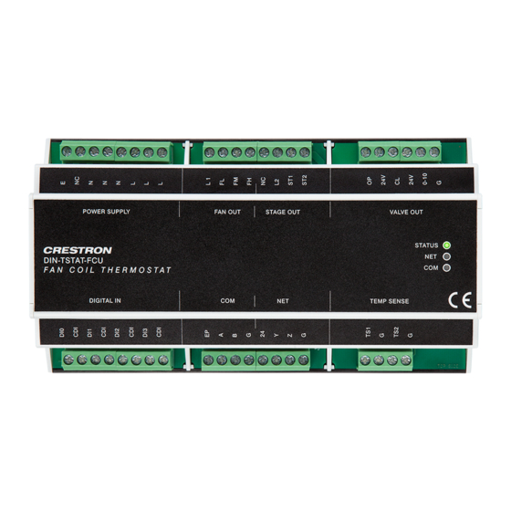
Page 6: Port Descriptions
20 A and the current through one relay must not be greater than 16 A. Port Descriptions The illustration below depicts the port arrangements of the DIN-TSTAT-FCU. The following table lists a description of the ports. -
Page 7: Safety Notes
The device contains electrical and electronic components and is not allowed to be disposed of as household refuse. All locally valid regulations and requirements must be observed. Setup and Commissioning Guide – DOC. 8207A DIN-TSTAT-FCU: DIN-Rail Fan-Coil Thermostat • 3... -
Page 8: Device Parameters
Device Parameters Using the DIN-TSTAT-FCU Commissioning Tool, configure the DIN-TSTAT-FCU according to the FCU type, valve parameters, and other requirements. Parameters are divided into common and specific to each FCU type. The common parameter to all FCUs that are subdivided by regulation, communication, and alarm parameters. - Page 9 Alarm 2 delay – Alarm 2 delay 2000 Alarm 3 enable – Alarm 3 enable – Alarm 3 polarity Alarm 3 active level (Continued on the following page) Setup and Commissioning Guide – DOC. 8207A DIN-TSTAT-FCU: DIN-Rail Fan-Coil Thermostat • 5...
-
Page 10: Regulation Algorithms
Regulation Algorithms The DIN-TSTAT-FCU is a universal fan-coil controller designed for two-pipe HVAC systems. The device controls the fan used for forcing air flow over the water coil and controls the valve used to adjust the water flow rate through the coil. The fan speed of the fan-coil unit is regulated with three speeds: low, medium, and high. -
Page 11: Fcu Wiring And Control
On power up, the device has an initialization period where the system is stabilized before temperature regulation can take place. The DIN-TSTAT-FCU’s normal operation can be interrupted if it receives an alarm signal or if the water temperature is inappropriate. -
Page 12: Initial Operating Parameters
∆T = �������������������� ���� �������� ���� ���� ���������������� × 0.5 °C EXPLANATION ������������ ���� ���� �������� ���� ���� ���� �������� ���������������� ���� ���� ���� ���� ∆T × 100% 1000 8 • DIN-TSTAT-FCU: DIN-Rail Fan-Coil Thermostat Setup and Commissioning Guide – DOC. 8207A... - Page 13 FAN OUT STAGE OUT VALVE OUT STATUS DIN-TSTAT-FCU TEMP SENSE DIGITAL IN COM: NET: TEMP SENSE: To the To the From the room control temperature controller system sensor Setup and Commissioning Guide – DOC. 8207A DIN-TSTAT-FCU: DIN-Rail Fan-Coil Thermostat • 9...
-
Page 14: Modulated Op-Cl 24 Vac Valve
1000 − ������������ ���� ���� �������� ���� ���� ���� �������� ���������������� ���� ���� ���� ���� ���� = ������������ ���� ���� �������� ���� �������� ���� ���� �������� ���� ���� × 1000 t when valve is closing 10 • DIN-TSTAT-FCU: DIN-Rail Fan-Coil Thermostat Setup and Commissioning Guide – DOC. 8207A... - Page 15 FAN OUT STAGE OUT VALVE OUT STATUS DIN-TSTAT-FCU DIGITAL IN TEMP SENSE COM: NET: TEMP SENSE: To the To the From the room control temperature controller system sensor Setup and Commissioning Guide – DOC. 8207A DIN-TSTAT-FCU: DIN-Rail Fan-Coil Thermostat • 11...
-
Page 16: Spring-Loaded 24 Vac Valve
∆T = �������������������� ���� �������� ���� ���� ���������������� × 0.5 °C PARAMETER EXPLANATION ������������ ���� ���� �������� ���� ���� ���� �������� ���������������� ���� ���� ���� ���� ∆T × 100% 1000 12 • DIN-TSTAT-FCU: DIN-Rail Fan-Coil Thermostat Setup and Commissioning Guide – DOC. 8207A... - Page 17 STAGE OUT VALVE OUT STATUS DIN-TSTAT-FCU DIGI T AL IN TEMP SENSE COM: NET: TEMP SENSE: To the To the From the room control temperature controller system sensor Setup and Commissioning Guide – DOC. 8207A DIN-TSTAT-FCU: DIN-Rail Fan-Coil Thermostat • 13...
-
Page 18: Modulated Op-Cl 230 Vac Valve
1000 − ������������ ���� ���� �������� ���� ���� ���� �������� ���������������� ���� ���� ���� ���� ���� = ������������ ���� ���� �������� ���� �������� ���� ���� �������� ���� ���� × 1000 t when valve is closing 14 • DIN-TSTAT-FCU: DIN-Rail Fan-Coil Thermostat Setup and Commissioning Guide – DOC. 8207A... - Page 19 STAGE OUT VALVE OUT STATUS DIN-TSTAT-FCU DIGI T AL IN TEMP SENSE COM: NET: TEMP SENSE: To the To the From the room control temperature controller system sensor Setup and Commissioning Guide – DOC. 8207A DIN-TSTAT-FCU: DIN-Rail Fan-Coil Thermostat • 15...
-
Page 20: Spring-Loaded 230 Vac Valve
∆T = �������������������� ���� ���� ���� ���� ���� ���������������� × 0.5 °C PARAMETER EXPLANATION ������������ ���� ���� �������� ���� ���� ���� �������� ���������������� ���� ���� ���� ���� ∆T Ymin = × 100% 1000 Ymin 16 • DIN-TSTAT-FCU: DIN-Rail Fan-Coil Thermostat Setup and Commissioning Guide – DOC. 8207A... - Page 21 POWER SUPP L Y VALVE OUT STATUS DIN-TSTAT-FCU DIGI T AL IN TEMP SENSE COM: NET: TEMP SENSE: To the To the From the room control temperature controller system sensor Setup and Commissioning Guide – DOC. 8207A DIN-TSTAT-FCU: DIN-Rail Fan-Coil Thermostat • 17...
-
Page 22: 1-2 Stage Direct-Expansion System
% Sp- set point ∆T – Step of temperature difference (∆T=N*0.5 °C, N is settable parameter) S2 – Stage 2 ON S1 – Stage 1 ON 18 • DIN-TSTAT-FCU: DIN-Rail Fan-Coil Thermostat Setup and Commissioning Guide – DOC. 8207A... - Page 23 STAGE OUT VALVE OUT STATUS DIN-TSTAT-FCU DIGI T AL IN TEMP SENSE COM: NET: TEMP SENSE: To the To the From the room control temperature controller system sensor Setup and Commissioning Guide – DOC. 8207A DIN-TSTAT-FCU: DIN-Rail Fan-Coil Thermostat • 19...
-
Page 24: Fan Speed Control
SpC – Set point for cooling ∆T – Step of temperature difference (∆T = �������������������� ���� �������� ���� ���� ���������������� × 0.5 °C) T – Room temperature 20 • DIN-TSTAT-FCU: DIN-Rail Fan-Coil Thermostat Setup and Commissioning Guide – DOC. 8207A... -
Page 25: Alarms
Temperature Probes DIN-TSTAT-FCU device has two resistance measuring inputs for NTC probes. First input is used for room temperature measurement. The second input can be used for water temperature monitoring. For the best results, use 20K NTC probes. -
Page 26: Cresnet ® Communications
0.5 W. Communication The device is reported as a DIN-TSTAT-FCU on the Cresnet network. The serial number is the same as serial number on the device label. While Cresnet communication is active, the NET LED is ON. -
Page 27: Joins
Analog Setpoint Output Joins JOIN TYPE JOIN NAME JOIN NUMBER Digital Mode_Heat_FB Digital Mode_Cool_FB Digital Mode_Off_FB Digital Is_Cooling_FB Digital Is_Heating_FB Digital Fan_High_FB (continued on the following page) Setup and Commissioning Guide – DOC. 8207A DIN-TSTAT-FCU: DIN-Rail Fan-Coil Thermostat • 23... -
Page 28: Light And Poll
2. The device blinks its NET LED to indicate that it is in Light and Poll mode. 3. Press the NET button to acknowledge the SLP command. This ends the Light and Poll procedure by sending an End Light and Poll (ELP) command. 24 • DIN-TSTAT-FCU: DIN-Rail Fan-Coil Thermostat Setup and Commissioning Guide – DOC. 8207A... -
Page 29: Aux Port
The auxiliary port has four pins marked EP, A, B, G, where EP is external power supply, A and B are + and – communication signals lines, and G is ground. Setup and Commissioning Guide – DOC. 8207A DIN-TSTAT-FCU: DIN-Rail Fan-Coil Thermostat • 25... -
Page 30: Communication
While communication is active, the COM LED blinks. If communication is error-free COM LED blinks fast, and each error will introduce a delay of 1s between the LED flashes. 26 • DIN-TSTAT-FCU: DIN-Rail Fan-Coil Thermostat Setup and Commissioning Guide – DOC. 8207A... -
Page 31: Registers
DIN-TSTAT-FCU over USB. Accessing USB Port USB port is located under the cover of the DIN-TSTAT-FCU. To open the cover, use a 2 mm wide flat screwdriver to gently pry the cover open using the four slots that are marked below. - Page 32 Releasing the Lid Accessing the USB Port 28 • DIN-TSTAT-FCU: DIN-Rail Fan-Coil Thermostat Setup and Commissioning Guide – DOC. 8207A...
-
Page 33: Usb Driver Installation Procedure
USB driver installation procedure is necessary only if the USB driver is not installed automatically after the USB cable is inserted. Before the USB driver is installed, please install DIN-TSTAT-FCU Configuration Tool. The USB driver installation procedure explained in this section is for Windows ®... - Page 34 6. Browse to the location that the DIN-TSTAT-FCU Configuration Tool is installed and then click Next. The default location is C:\Program Files (x86)\Crestron\DIN-TSTAT-FCU Configuration Tool. 7. If the Windows Security window appears, click Install this driver software anyway 30 • DIN-TSTAT-FCU: DIN-Rail Fan-Coil Thermostat...
-
Page 35: Install The Din-Tstat-Fcu Configuration Tool
Install the DIN-TSTAT-FCU Configuration Tool To install the DIN-TSTAT Configuration Tool, do the following: 1. Double-click the DIN-TSTAT-FCU Configuration Tool.exe file to begin installation. Setup and Commissioning Guide – DOC. 8207A DIN-TSTAT-FCU: DIN-Rail Fan-Coil Thermostat • 31... - Page 36 2. Enter the installation destination in the “Setup -Select Destination Location” window. The default installation destination “C:\Program Files (x86)\Crestron\DIN-TSTAT-FCU Configuration Tool”. Click Next. 3. In the “Setup – Select Start Menu Folder,” set the installation options for creating a shortcut for the configuration tool in the Start Menu folder. Click Next.
- Page 37 4. In the “Setup – Select Additional Tasks” window, select or clear the Create a desktop shortcut check box to create a shortcut to the DIN-TSTAT-FCU Configuration tool on your desktop. Click Next. 5. The DIN-TSTAT-FCU Configuration tool is installed. Upon completion, a summary window is displayed gives the option to start the application.
-
Page 38: Using The Din-Tstat-Fcu Configuration Tool
Launch DIN-TSTAT-FCU Configuration Tool check box to open the program after exiting the installation process. Click Finish to exit the installation process. Using the DIN-TSTAT-FCU Configuration Tool The DIN-TSTAT-FCU Configuration Tool sets the parameters for the DIN-TSTAT-FCU. Menu Overview The menu bar contains File, ComPort, Device, and Help menus that provide access to various setup and operation features. -
Page 39: Comport Menu
Click the Scan Ports button to identify and list all used ports in the system. Select the port that the DIN-TSTAT-FCU uses to communicate from the drop-down list. Click OK to save the settings and exit the menu. Click Cancel to discard the settings and exit. - Page 40 2. Click the Update button to load the firmware onto the DIN-TSTAT-FCU. OS Update The “OS Update” window allows an updated OS to be loaded to the DIN-TSTAT-FCU. The information about the current OS in the device is displayed in the “OS Info” section of the window.
- Page 41 NOTE: The USB cable must be removed and then reinserted into the DIN-TSTAT-FCU before continuing. 5. Click Scan ports, and then select the port with which the DIN-TSTAT-FCU is associated. 6. Click Next. 7. Click Update to start the OS update process.
- Page 42 The USB cable must be removed and then reinserted into the DIN-TSTAT-FCU before continuing. 3. Press Scan and then select the port with which the DIN-TSTAT-FCU is associated. 38 • DIN-TSTAT-FCU: DIN-Rail Fan-Coil Thermostat Setup and Commissioning Guide – DOC. 8207A...
- Page 43 Restart The “Restart” window allows the device to be restarted. When restarted, the DIN-TSTAT-FCU is put into idle state, and then put into a normal operating state. Help Menu The Help menu contains About, DIN-TSTAT-FCU specifications, and Program Help options.
-
Page 44: Configure The Din-Tstat-Fcu
Configure the DIN-TSTAT-FCU NOTE: When the DIN-TSTAT-FCU Configuration Tool is run for the first time, it searches for available ports. If only one port is discovered, it connects to the DIN-TSTAT-FCU associated with that port. Upon subsequent starts, it loads the port used during the last session. -
Page 45: Monitoring
Stop - Stops the monitoring process. All functionalities are enabled. Monitoring table: Name – the name of the variable. Value – the read value from the device. Setup and Commissioning Guide – DOC. 8207A DIN-TSTAT-FCU: DIN-Rail Fan-Coil Thermostat • 41... -
Page 46: Variable Forcing
Force to force the value. To stop forcing the value and return it to the previous state, click Deforce. Troubleshooting Error Code Using Cresnet, the DIN-TSTAT-FCU can report certain errors. The errors are bit coded in FCU_type join as presented in the table below. Error Codes ERROR... -
Page 47: Troubleshooting
Troubleshooting The following provides corrective actions for possible trouble situations. If further assistance is required, please contact a Crestron customer service representative. DIN-TSTAT-FCU Troubleshooting TROUBLE POSSIBLE CAUSE(S) ACTION The LED indicators Power is not being Check the ac and Cresnet wiring. - Page 48 The wrong operating Using the DIN-TSTAT-FCU Configuration mode is active. Tool in Monitoring mode, check the Selected mode value. (continued on the following page) 44 • DIN-TSTAT-FCU: DIN-Rail Fan-Coil Thermostat Setup and Commissioning Guide – DOC. 8207A...
- Page 49 Stage 1 or 2 relay output variables. Use the forcing option to place the outputs in the desired state regardless of the current regulation state. (continued on the following page) Setup and Commissioning Guide – DOC. 8207A DIN-TSTAT-FCU: DIN-Rail Fan-Coil Thermostat • 45...
- Page 50 Tool in Monitoring mode, check the binary input and alarm statuses. Use the force option to place the input in the desired state. (Continued on the following page) 46 • DIN-TSTAT-FCU: DIN-Rail Fan-Coil Thermostat Setup and Commissioning Guide – DOC. 8207A...
- Page 51 Using the DIN-TSTAT-FCU Configuration Tool in Monitoring mode, check the binary input and the alarm statuses. Use the force option to place the input in the desired state. Setup and Commissioning Guide – DOC. 8207A DIN-TSTAT-FCU: DIN-Rail Fan-Coil Thermostat • 47...
- Page 52 Crestron Electronics, Inc. Setup and Commissioning Guide – DOC. 8207A 15 Volvo Drive Rockleigh, NJ 07647 (2048992) Tel: 888.CRESTRON 08.17 Fax: 201.767.7576 Specifications subject to www.crestron.com change without notice.
Need help?
Do you have a question about the DIN-TSTAT-FCU and is the answer not in the manual?
Questions and answers