Table of Contents
Advertisement
Quick Links
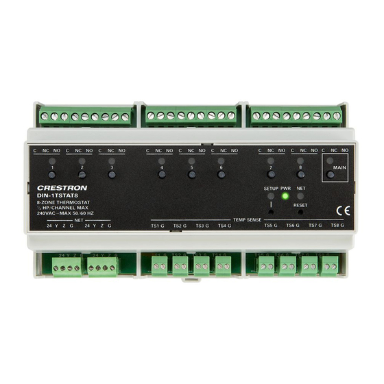
DIN-1TSTAT8
8-Zone Radiant Heat Thermostat, DIN Rail Mount
Installation Guide
Description
Control up to eight radiant heating zones using one DIN-TSTAT8 thermostat. The
thermostat mounts remotely allowing low-profile remote temperature sensors to be
installed in each zone. Easily adjust the temperature setting in each heat zone with a
Crestron
touchscreen, handheld remote, or mobile app.
®
The thermostat controls up to eight SPDT heat zone valves and one SPDT main control
valve. Use normally closed (NC) or normally open (NO) control valves that are rated at
1/2 HP at 240 VAC, 50/60 Hz.
Failsafe Mode maintains the temperature in each zone to provide comfort and to prevent
frozen pipes if the user setpoint is temporarily lost.
Additional Resources
Visit the product page on the Crestron website (www.crestron.com) for
additional information and the latest firmware updates. Click the QR
code or use a QR reader application on your mobile device to scan the
QR image.
Install the DIN-1TSTAT8
NOTE: Observe the following points when installing the DIN-1TSTAT8.
• Use the DIN-1TSTAT8 in an electrical panel with DIN rail mounting provisions.
• Mount the DIN-1TSTAT8 in a well-ventilated area.
• Do not block the venting holes.
• Certain third-party DIN cabinets provide space for an informational label
between each DIN rail row. Crestron's Engraver software (version 4.0 or later)
can generate appropriate labels for all Crestron DIN rail products.
Mount the DIN-1TSTAT8 to the DIN rail (not included):
1. Hang the DIN-1TSTAT8 on the top of the DIN rail.
2. Press the bottom toward the DIN rail and snap it into place.
DIN rail release
Remove the DIN-1TSTAT8 from the DIN rail:
1. Turn off power to the thermostat and the heating system.
2. Remove all connections from the DIN-1TSTAT8.
3. Use a small, flat-head screwdriver to pull the DIN rail release tab down.
4. Tilt the bottom of the DIN-1TSTAT8 away from the bottom of the DIN rail and then
remove the thermostat.
Wire the DIN-1TSTAT8
Make the following connections to the thermostat.
C (common), NC (normally closed), and
NO (normally open) to relays 1-8
Cresnet control from a control system
and to daisy-chained Cresnet device
Zone Valve and Main Valve Connections (1-8, MAIN)
1. Wire the eight zone valves to the 1-8 terminals on the thermostat. Connect one zone
valve per heat zone. Each zone valve must have a corresponding temperature sensor
connected.
2. Wire the main control valve to the MAIN terminal on the thermostat. Do not connect
a zone valve to the MAIN port.
• For 2-wire, normally open valves, connect the NO terminal on the thermostat to
• For 3-wire valves, connect the NO terminal on the thermostat to the OPEN
DIN-1TSTAT8
For zone valve specifications and wiring, refer to the documentation provided by the valve
manufacturer.
230 VAC
DIN Rail
N
(not included)
Temperature Sensor Connections (TEMP SENSE)
Wire the eight temperature sensors to the TEMP SENSE terminals. Connecting a
temperature sensor input enables the use of the corresponding zone valve. Connect one
temperature sensor per heat zone. Crestron recommends using CAT3 (up to 76 meters
(250 feet)) or CAT5 up to 152 meters (500 feet)) network cable. If other wire is used, the
total capacitance must be less than 7,000 pF (up to 152 meters (500 feet).
NOTE: When wiring the temperature sensors:
• Use a separate run of wire for each sensor. If using multi-conductor cable, use
• Do not run temperature sensor lines parallel to any other wiring. Cross cables at
• In situations where ordinary two-conductor thermostat wire (18 to 20 gauge) has
Cresnet Connections (NET)
Wire the Crestron control system, and other daisy-chained Cresnet devices, to the NET
terminals on the thermostat.
1-8:
NET:
Temperature sensor (TS) input from
the OPEN terminal on the valve.
terminal on the valve and then connect the NC terminal on the thermostat to the
CLOSE terminal on the valve.
Valve
Open
L
Com
M
Close
only one pair per cable.
right angles.
been installed, it may be used for runs up to 30 meters (100 feet). This is not a
preferred method of installation.
MAIN:
C (common), NC (normally closed), and
NO (normally open) to the main valve
MAIN
TEMP SENSE:
remote temperature sensors
Wiring is typical for
the zone valves
and the main valve.
MAIN
Advertisement
Table of Contents

Related Manuals for Crestron DIN-1TSTAT8


Summary of Contents for Crestron DIN-1TSTAT8
- Page 1 3. Use a small, flat-head screwdriver to pull the DIN rail release tab down. MAIN 4. Tilt the bottom of the DIN-1TSTAT8 away from the bottom of the DIN rail and then remove the thermostat. Temperature Sensor Connections (TEMP SENSE) Wire the eight temperature sensors to the TEMP SENSE terminals.
- Page 2 Crestron disclaims compliance could void the user’s authority to operate the equipment. any proprietary interest in the marks and names of others. Crestron is not responsible for errors in typography or photography.
Need help?
Do you have a question about the DIN-1TSTAT8 and is the answer not in the manual?
Questions and answers