Crestron Horizon HZ-THSTAT Product Manual
Wireless thermostat
Hide thumbs
Also See for Horizon HZ-THSTAT:
- Quick start manual (14 pages) ,
- Product manual (179 pages)
Table of Contents
Advertisement
Advertisement
Table of Contents

Related Manuals for Crestron Horizon HZ-THSTAT


Summary of Contents for Crestron Horizon HZ-THSTAT
- Page 1 HZ-THSTAT Horizon® Wireless Thermostat Product Manual Crestron Electronics, Inc.
- Page 2 Other trademarks, registered trademarks, and trade names may be used in this document to refer to either the entities claiming the marks and names or their products. Crestron disclaims any proprietary interest in the marks and names of others. Crestron is not responsible for errors in typography or photography.
-
Page 3: Table Of Contents
Contents Overview Supported Systems Specifications Dimensions Installation System Connections R CONNECTIONS Switch Thermistor Curve Wiring Diagrams Single Stage Heat-Only System without Common Wire Single Stage Heat/Cool System without Common Wire Single Stage Heat/Cool System Single Stage Heat Pump with Aux Heat 2 Stage Heat Pump with 2 Stage Aux Heat Dual Stage Heat/Cool System with Separate References and Humidification Wiring a Local Power Source... - Page 4 Display Wireless Network Location Diagnostics About Reboot Restore Device System Setup System Type Definitions Radiant Floor Heating Definitions Heat/Cool, 1 or 2 Stages, Forced Air or Radiant System Type System Performance User Controls Sensor Setup Humidistat Setup Heat Pump, 1 or 2 Stages, Aux Heat or Dual Fuel System Type System Performance User Controls...
- Page 5 System Performance User Controls Sensor Setup Humidstat Setup 2 Stage Heat (Stage 1 Radiant Floor)/1 Stage Cool Heat Pump with 1 Stage Aux Heat Radiant Floor System Type System Performance User Controls Sensor Setup Humidistat Setup 2 Stage Heat (Stage 1 Radiant Floor Warming/Space Heating)/1 Stage Cool Radiant Floor System Type System Performance...
- Page 6 iv • Contents Product Manual — Doc. 8622B...
-
Page 7: Overview
The RGB backlit status light bar indicates HVAC calls. The thermostat behavior can be customized separately for day and night operating modes. With Crestron Toolbox® software, the thermostat can be configured and debugged remotely, and the thermostat configurations can be saved and accessed for reference. Detailed system logging offers the opportunity to diagnose HVAC, sensor, or network issues. -
Page 8: Specifications
1, 2, or 3 stage heat (stage 1 radiant floor with or without floor warming), 1 or 2 stage cool dual fuel heat pump with 1 stage aux heat NOTES: 2-stage heating: Unlike traditional furnaces that turn on and run at full capacity with each demand for heating, 2-stage heat operates like two separate furnaces to maintain a more consistent temperature in the home. - Page 9 Specification Details Communications WiFi® communications 802.11/b/g/n (2.4 GHz) Buttons Raises the room’s setpoint by 1ºF, 1ºC, or 0.5ºC, depending on the active temperature scale Down Lowers the room’s setpoint by 1ºF, 1ºC, or 0.5ºC, depending on the active temperature scale Display Type Transflective LCD, backlit...
-
Page 10: Dimensions
Dimensions 4 • HZ-THSTAT Product Manual — Doc. 8622B... -
Page 11: Installation
Installation NOTE: Installers should have a strong working knowledge of HVAC systems. The thermostat can be mounted directly to drywall, a low voltage mounting bracket (not included), or to an electrical box (not included) for new or old work applications. For mounting and installation instructions, refer to the HZ-THSTAT Quick Start. -
Page 12: System Connections
System Connections Use the connections on the backplate to wire the thermostat to the HVAC system. Connections and Controls Description (1) Common from HVAC system 24VAC transformer. Used to power the device. (1) Reference for heat calls (W/W2) when using two separate reference connections. Used to power the device. - Page 13 CAUTION: To avoid a possible short circuit, ensure excess wire is pushed back through the hole in the backplate. NOTES: This device is rated for 24VAC operation. For installations without a common wire, the HZA-CONV-THSTAT-2WIRE 2-wire power adapter (sold separately) may be used. Refer to the Wiring Diagrams (on page 9) section for wiring details.
-
Page 14: R Connections Switch
R CONNECTIONS Switch The thermostat pulls power from both R terminals and the C terminal. The position of the R Connections switch decides which R connection is routed to the heat calls (W/W2). NOTES: When using the HZA-CONV-THSTAT-2WIRE, always make connections to the R/RC terminals and set the switch to R/RC ONLY. -
Page 15: Thermistor Curve
Thermistor Curve The thermostat is compatible with Crestron remote sensors and 10K thermistors. Refer to the table for information on the supported thermistor temperature curve. Temperature k-ohm -30°F (-34.4°C) 185.42 0°F (-17.8°C) 81.72 40°F (4.4°C) 26.11 80°F (26.7°C) 9.37 90°F (32.2°C) 7.41... -
Page 16: Single Stage Heat-Only System Without Common Wire
Single Stage Heat-Only System without Common Wire NOTE: This wiring is also applicable for a Radiant Floor Only (Floor Warming and/or Space Heating) system without Common Wire. 10 • HZ-THSTAT Product Manual — Doc. 8622B... -
Page 17: Single Stage Heat/Cool System Without Common Wire
Single Stage Heat/Cool System without Common Wire Product Manual — Doc. 8622B HZ-THSTAT • 11... -
Page 18: Single Stage Heat/Cool System
Single Stage Heat/Cool System 12 • HZ-THSTAT Product Manual — Doc. 8622B... -
Page 19: Single Stage Heat Pump With Aux Heat
Single Stage Heat Pump with Aux Heat Product Manual — Doc. 8622B HZ-THSTAT • 13... -
Page 20: Stage Heat Pump With 2 Stage Aux Heat
2 Stage Heat Pump with 2 Stage Aux Heat 14 • HZ-THSTAT Product Manual — Doc. 8622B... -
Page 21: Dual Stage Heat/Cool System With Separate References And Humidification
Dual Stage Heat/Cool System with Separate References and Humidification Product Manual — Doc. 8622B HZ-THSTAT • 15... -
Page 22: Wiring A Local Power Source
Wiring a Local Power Source NOTE: If the HVAC system only requires one reference, a 24VAC power source can be used to power the device locally. 16 • HZ-THSTAT Product Manual — Doc. 8622B... -
Page 23: Radiant Floor Only (Floor Warming And/Or Space Heating)
Radiant Floor Only (Floor Warming and/or Space Heating) Product Manual — Doc. 8622B HZ-THSTAT • 17... -
Page 24: Stage Heat (Stage 1 Radiant Floor)/1 Stage Cool Or 1 Stage Heat/1 Stage Cool With Floor Warming
2 Stage Heat (Stage 1 Radiant Floor)/1 Stage Cool or 1 Stage Heat/1 Stage cool with Floor Warming 18 • HZ-THSTAT Product Manual — Doc. 8622B... -
Page 25: Stage Heat (Stage 1 Radiant Floor)/1 Stage Cool Heat Pump With 1 Stage Aux Heat Or 1 Stage Heat/1 Stage Cool Heat Pump With 1 Stage Aux Heat And Floor Warming
2 Stage Heat (Stage 1 Radiant Floor)/1 Stage Cool Heat Pump with 1 Stage Aux Heat or 1 Stage Heat/1 Stage Cool Heat Pump with 1 Stage Aux Heat and Floor Warming Product Manual — Doc. 8622B HZ-THSTAT • 19... -
Page 26: Stage Heat (Stage 1 Radiant Floor)/2 Stage Cool Heat Pump With 1 Stage Aux Heat Or 2 Stage Heat/2 Stage Cool Heat Pump With 1 Stage Aux Heat And Floor Warming
3 Stage Heat (Stage 1 Radiant Floor)/2 Stage Cool Heat Pump with 1 Stage Aux Heat or 2 Stage Heat/2 Stage Cool Heat Pump with 1 Stage Aux Heat and Floor Warming 20 • HZ-THSTAT Product Manual — Doc. 8622B... -
Page 27: Remote Thermostat Setup
Setup, configure, and update the thermostat remotely via Crestron Toolbox™ software, which provides the same configuration options as the HZ-THSTAT. Create template configurations to easily setup multiple thermostats at one time. Crestron Toolbox software provides access to detailed logs NOTES: ... -
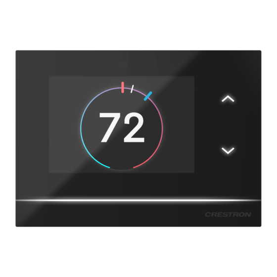
Page 28: Thermostat Operation
Thermostat Operation The HZ-THSTAT has a 3.5 in. LCD touchscreen display used for configuring the thermostat to the HVAC system and monitoring the temperature and humidity. NOTE: The screenshots below show the thermostat with the Wi-Fi® network connected. 22 • HZ-THSTAT Product Manual —... - Page 29 Product Manual — Doc. 8622B HZ-THSTAT • 23...
-
Page 30: Lightbar And Up/Down Buttons
The previous screenshots were taken from a white thermostat in day mode. Almond and Black thermostats have Almond and Dark themes, respectively. In night mode, White and Almond thermostats switch to a dark theme and appear as shown below. Lightbar and Up/Down Buttons The RGB lightbar and capacitive Up/Down buttons change colors based on the call: ... -
Page 31: Weather
The Up/Down buttons are used to change the heat and cool setpoints and to access the Installer Settings. When using the Up/Down buttons in Dual Setpoint mode, the thermostat attempts to assume which setpoint the user wants to adjust. To adjust a different setpoint, use the gauge or tap the desired setpoint handle and tap the Up/Down buttons to move it. -
Page 32: Side Menu
Side Menu The Side menu provides the end user easy access to system controls. To open the Side menu, swipe the screen from the right side of the screen toward the center, and tap the desired menu option. The Side menu options shown by default are MODE, FAN, and HUMIDITY. FLOOR appears as a menu item if Radiant Floor is set to Floor Warming or Floor Warm/Space Heat. - Page 33 MODE: Select the desired Mode for the configured system. Select Cool to control the cooling system. Select Heat to control the heating system. Select Aux Heat (only for Heat Pump systems) to shut off the Heat Pump and force heat only mode using the Auxiliary Heat stages.
-
Page 34: Brightness Slider, Settings, And Installer Settings
HUMIDITY: Tap HUMIDITY to turn the Humidistat on or off. Either Humidify or Dehum (dehumidify) will show depending on whether Humidification of Dehumidification is set in Humidistat Setup. FLOOR: Tap FLOOR to turn the Floor Warming system on or off. FLOOR only appears if Radiant Floor is set to Floor Warming or Floor Warm/Space Heat. - Page 35 To open the SETTINGS screen: 1. On the Brightness slider, tap the gear icon. 2. Tap Display or Wireless Network to adjust the settings. These are easy-to-access settings for the end user. Refer to Display (on the next page)and Wireless Network (on page 32) details.
-
Page 36: Display
To open INSTALLER SETTINGS: From the SETTINGS screen, tap the following sequence on the Up/Down button: Up, Up, Down, Down. Refer to Installer Settings (on page 33) for details. Display Use the DISPLAY screens to adjust the display and backlight settings for both day and night themes. - Page 37 Day and Night Display settings: Timeout: Tap to enable or disable timeout settings for the Display, Lightbar, and capacitive buttons when there is no user interaction. Wake On Motion: Tap to enable or disable the Wake on Motion feature. Enable to wake the thermostat from timeout when motion or proximity to the sensor is detected.
-
Page 38: Wireless Network
Wireless Network The WIRELESS NETWORK provides quick access to limited network settings and information. For more wireless network settings, refer to Installer Settings (on the facing page). Wireless Networks: Lists the available networks. Tap Refresh to update the list of available networks. ... -
Page 39: Installer Settings
Tap on a listed network to set it as the preferred network, change the password, or delete the network. Installer Settings Installer Settings provides in-depth settings data for configuring the thermostat. The topics include: Product Manual (on the next page) ... -
Page 40: Product Manual
Product Manual PRODUCT MANUAL provides a QR code to this Product Manual. Scan the QR code with a smart device to access the Product Manual at any time. System Configuration Use SYSTEM CONFIGURATION to configure the thermostat to work with the connected HVAC system. -
Page 41: End User Access
End User Access END USER ACCESS allows the installer to limit access to the Fan Control, Humidistat Control, and Radiant Floor menu options available on the home screen Side menu and the Radiant Floor or Humidistat pages on the home screen. Tap the toggle beside Fan Control, Humidistat Control, or Radiant Floor Control to remove it from the Side menu. -
Page 42: Location
IP Table Setup allows the thermostat to be connected to a control system. An IP Table is a lookup table used by Crestron Ethernet devices to map between IP IDs and IP addresses. Refer to the control system documentation for details. -
Page 43: Diagnostics
NOTE: United States residents only can enter the Postal Code. Residents outside the United States can enter the latitude and longitude. Diagnostics Use DIAGNOSTICS to test the HVAC system calls, review call log summaries, sensor log summaries, or review system settings. ... -
Page 44: About
Sensor Summary: Provides more details about the local and remote sensors. As with Min/Max/Average temperature/humidity and error counts, information can be filtered by Day, Week, or Month and specific days, weeks, or months. System Overview: Details System Configuration at a glance. About Displays firmware version, update methods, and product information. -
Page 45: Restore Device
Restore Device To restore the thermostat to factory settings, tap Yes. Tap No to return to INSTALLER SETTINGS. Product Manual — Doc. 8622B HZ-THSTAT • 39... -
Page 46: System Setup
System Setup The following are system type and radiant floor definitions. System Type Definitions One or Two Stage Heat/Cool Systems Unlike traditional furnaces that turn on and run at full capacity with each demand for heating, 2- stage furnaces operate like two separate furnaces. The unit begins to run in its first stage, and operates at a fraction of its heating capacity. - Page 47 Space Heating: Maintains a particular air temperature using the radiant floor heat to heat the space. Does not heat over the radiant floor maximum temperature even if this results in the space being under-heated. Connection to the radiant floor output relay is terminal ...
- Page 48 2 Stage Heat (Stage 1 Radiant Floor)/1 Stage Cool Heat Pump with 1 Stage Aux Heat (on page 101) 2 Stage Heat (Stage 1 Radiant Floor Warming/Space Heating)/1 Stage Cool (on page 113) 2 Stage Heat (Stage 1 Radiant Floor Warming/Space Heating)/1 Stage Cool Heat Pump with 1 Stage Aux Heat (on page 125) NOTES: ...
-
Page 49: Heat/Cool, 1 Or 2 Stages, Forced Air Or Radiant
Heat/Cool, 1 or 2 Stages, Forced Air or Radiant Navigate to the SYSTEM CONFIGURATION settings. System Type System Type: Select Heat/Cool NOTE: There are Heat Only and Cool Only options for a Heat Only or Cool Only system type. Fan In Heat: Select Yes or No. -
Page 50: System Performance
Cool Stages: Select 1 or 2. Default setting: 1. Number of cool-only (air conditioning) stages present. System Performance Heat Anticipator: Select 1, 2, 3, 4, 5, or 6. Default setting: 3. For example, to adjust space heating system cycling characteristics., select 1 for more frequent cycles and faster responses or 6 for less frequent cycles and slower responses. - Page 51 Accumulated Staging Index: Select 1, 2, 3, 4, 5, or 6. Default setting: 3. Triggers next stage to meet demand in instances where the previous stage cannot reach the Interstage Differential or achieve the desired setpoint. For example, select 1 for a faster trigger to the next stage or 5 for a slower trigger to the next stage.
-
Page 52: User Controls
User Controls Auto Setpoint: Select Dual, Single, or Disabled. Default setting: Dual. Defines Auto mode. Dual: Auto mode uses heat and cool setpoints. Single: Auto mode uses single (auto) setpoint. Disabled: Auto mode is disabled. NOTE: Auto Setpoint cannot be accessed in Heat Only or Cool Only system. - Page 53 Lower Setpoint: Select 38 - 79 for Fahrenheit (3 - 27 for Celsius).Default setting: 38 for Fahrenheit (3 for Celsius) Limits minimum heat setpoint the end user can set. Upper Setpoint: Select 48 - 89 for Fahrenheit (8 - 32 for Celsius). Default setting: 89 for Fahrenheit (32 for Celsius) Limits the maximum heat setpoint the end user can set.
- Page 54 Lower Setpoint: Select 38 - 89 for Fahrenheit (3 - 32 for Celsius). Default setting: 59 for Fahrenheit (15 for Celsius). Limits minimum auto setpoint the end user can set. Upper Setpoint: Select 48 - 99 for Fahrenheit (8 - 37 for Celsius). Default setting: 99 for Fahrenheit (37 for Celsius).
-
Page 55: Sensor Setup
NOTE: Auto Deadband cannot be accessed in the following instances: Heat Only systems Cool Only systems Auto Setpoint is set to Disable. Sensor Setup Local Sensor Usage: Select Omit or Space. Default setting: Space. Defines how the local sensor is used by the thermostat. ... - Page 56 Local Sensor Temperature Trim: Select -6 to +6 for Fahrenheit (-3.0 to +3.0 for Celsius). Default setting: 0. Adjusts local sensor temperature measurement. TS1 Temperature Trim: Select -6 to +6 for Fahrenheit (-3.0 to +3.0 for Celsius). Default setting: 0. Adjusts temperature sensed by temperature sensor(s) attached to TS1 input.
- Page 57 Local Sensor Humidity Trim: Select -9.0 to +9.0. Default setting: 0. Adjusts local sensor humidity percentage. TS1 Humidity Trim: Select -9.0 to +9.0. Default setting: 0. Adjusts humidity percentage sensed by temperature/humidity sensor attached to TS1 input. TS2 Humidity Trim: Select -9.0 to +9.0. Default setting: 0. Adjusts humidity percentage sensed by temperature/humidity sensor attached to TS2 input.
-
Page 58: Humidistat Setup
Humidistat Setup Invert Call Logic: Tap the toggle to invert the call logic. Default: No. Reverses the logic controlling the switching of the HUM relay (NO/NC). Humidistat Setup: Select Humidification, Dehumidification, or Off. Default setting: Humidification. Sets the operating mode of the HUM relay. ... - Page 59 Lower Setpoint: Select 5 - 80. Default setting: 10. Limits minimum humidistat setpoint percentage. Upper Setpoint: Select 15 - 90. Default setting: 70. Limits maximum humidistat setpoint percentage. NOTE: The Upper Setpoint must be 10% higher than the Lower Setpoint. Product Manual —...
-
Page 60: Heat Pump, 1 Or 2 Stages, Aux Heat Or Dual Fuel
Heat Pump, 1 or 2 Stages, Aux Heat or Dual Fuel Navigate to the SYSTEM CONFIGURATION settings. System Type System Type: Select Heatpump w/ Aux or Dual Fuel Heatpump Heat Pump w/ Aux or Dual Fuel Heat Pump: Dual Fuel runs either the heat pump or the aux output, depending on outdoor temperature. -
Page 61: System Performance
Fan In Heat options change if Heat Stages is set to 2. Select one of the following options: Yes: Fan called for first and second stage (W/W2). W2 Only:Fan called for second stage (W2) only. No: Disable fan call operation for heat calls. ... - Page 62 Accumulated Staging Index: Select 1, 2, 3, 4, 5, or 6. Default setting: 3. Triggers next stage to meet demand in instances where the previous stage cannot reach the Interstage Differential or achieve the desired setpoint. For example, select 1 for a faster trigger to the next stage or 5 for a slower trigger to the next stage.
-
Page 63: User Controls
Auxiliary Heat Balance Point: Select N/A or 0 - 90 for Fahrenheit (-18 - 31 for Celsius). Default setting: N/A. Maximum outdoor temperature at which Auxiliary heat system supplements the heat pump (requires an outdoor temperature sensor). NOTES: Auxiliary Heat Balance Point: ... - Page 64 Lower Setpoint: Select 38 - 79 for Fahrenheit (3 - 27 for Celsius).Default setting: 38 for Fahrenheit (3 for Celsius) Limits minimum heat setpoint the end user can set. Upper Setpoint: Select 48 - 89 for Fahrenheit (8 - 32 for Celsius). Default setting: 89 for Fahrenheit (32 for Celsius) Limits the maximum heat setpoint the end user can set.
- Page 65 Lower Setpoint: Select 38 - 89 for Fahrenheit (3 - 32 for Celsius). Default setting: 59 for Fahrenheit (15 for Celsius). Limits minimum auto setpoint the end user can set. Upper Setpoint: Select 48 - 99 for Fahrenheit (8 - 37 for Celsius). Default setting: 99 for Fahrenheit (37 for Celsius).
-
Page 66: Sensor Setup
NOTE: Auto Deadband cannot be accessed in the following instances: Heat Only systems Cool Only systems Auto Setpoint is set to Disable. Sensor Setup Local Sensor Usage: Select Omit or Space. Default setting: Space. Defines how the local sensor is used by the thermostat. ... - Page 67 Local Sensor Temperature Trim: Select -6 to +6 for Fahrenheit (-3.0 to +3.0 for Celsius). Default setting: 0. Adjusts local sensor temperature measurement. TS1 Temperature Trim: Select -6 to +6 for Fahrenheit (-3.0 to +3.0 for Celsius). Default setting: 0. Adjusts temperature sensed by temperature sensor(s) attached to TS1 input.
- Page 68 Local Sensor Humidity Trim: Select -9.0 to +9.0. Default setting: 0. Adjusts local sensor humidity percentage. TS1 Humidity Trim: Select -9.0 to +9.0. Default setting: 0. Adjusts humidity percentage sensed by temperature/humidity sensor attached to TS1 input. TS2 Humidity Trim: Select -9.0 to +9.0. Default setting: 0. Adjusts humidity percentage sensed by temperature/humidity sensor attached to TS2 input.
-
Page 69: Humidistat Setup
Humidistat Setup Invert Call Logic: Tap the toggle to invert the call logic. Default: No. Reverses the logic controlling the switching of the HUM relay (NO/NC). Humidistat Setup: Select Humidification, Dehumidification, or Off. Default setting: Humidification. Sets the operating mode of the HUM relay. ... - Page 70 Lower Setpoint: Select 5 - 80. Default setting: 10. Limits minimum humidistat setpoint percentage. Upper Setpoint: Select 15 - 90. Default setting: 70. Limits maximum humidistat setpoint percentage. NOTE: The Upper Setpoint must be 10% higher than the Lower Setpoint. 64 •...
-
Page 71: Radiant Floor Only (Floor Warming)
Radiant Floor Only (Floor Warming) Navigate to the SYSTEM CONFIGURATION settings. Radiant Floor Radiant Type: Select Floor Warming Regulation Index: Select 1, 2, 3, 4, 5, or 6. Default setting: 3. For example, to adjust Floor Warming system cycling characteristics, select 1 for a narrow temperature regulation or 6 for a wide temperature regulation. -
Page 72: System Type
Lower Setpoint: Select 38 - 100 for Fahrenheit (3 - 38 for Celsius). Default setting: 38 for Fahrenheit (3 for Celsius). Limits minimum floor warming setpoint. Upper Setpoint : Select 48 - 110 for Fahrenheit (8 - 43 for Celsius). Default setting: 110 for Fahrenheit (43 for Celsius). -
Page 73: User Controls
User Controls Setpoint Units: Select 1F, 1C, or 0.5C. Default setting: 1F. Defines the temperature scale as Fahrenheit or Celsius, and determines the setpoint incrementation by 1°F, 1°C, or 0.5°C. NOTE: The Setpoint Units setting will also be applied to the sensor readings. ... -
Page 74: Sensor Setup
Sensor Setup NOTE: Requires a slab remote sensor (CHV-RSS, sold separately). Local Sensor Usage: Select Omit or Space. Default setting: Space. Defines how the local sensor is used by the thermostat. Omit: Omits channel from thermostat operation NOTE: Sensor temperature and humidity can be output to the network even if Omit is selected. - Page 75 Local Sensor Temperature Trim: Select -6 to +6 for Fahrenheit (-3.0 to +3.0 for Celsius). Default setting: 0. Adjusts local sensor temperature measurement. TS1 Temperature Trim: Select -6 to +6 for Fahrenheit (-3.0 to +3.0 for Celsius). Default setting: 0. Adjusts temperature sensed by temperature sensor(s) attached to TS1 input.
- Page 76 Local Sensor Humidity Trim: Select -9.0 to +9.0. Default setting: 0. Adjusts local sensor humidity percentage. TS1 Humidity Trim: Select -9.0 to +9.0. Default setting: 0. Adjusts humidity percentage sensed by temperature/humidity sensor attached to TS1 input. TS2 Humidity Trim: Select -9.0 to +9.0. Default setting: 0. Adjusts humidity percentage sensed by temperature/humidity sensor attached to TS2 input.
-
Page 77: Humidistat Setup
Humidistat Setup Invert Call Logic: Tap the toggle to invert the call logic. Default: No. Reverses the logic controlling the switching of the HUM relay (NO/NC). Humidistat Setup: Select Humidification, Dehumidification, or Off. Default setting: Humidification. Sets the operating mode of the HUM relay. ... - Page 78 Lower Setpoint: Select 5 - 80. Default setting: 10. Limits minimum humidistat setpoint percentage. Upper Setpoint: Select 15 - 90. Default setting: 70. Limits maximum humidistat setpoint percentage. NOTE: The Upper Setpoint must be 10% higher than the Lower Setpoint. 72 •...
-
Page 79: Radiant Floor Only (Space Heating)
Radiant Floor Only (Space Heating) Navigate to the SYSTEM CONFIGURATION settings. Radiant Floor Radiant Type: Select Space Heating Regulation Index: Select 1, 2, 3, 4, 5, or 6. Default setting: 3. For example, to adjust Floor Warming system cycling characteristics, select 1 for a narrow temperature regulation or 6 for a wide temperature regulation. -
Page 80: System Type
NOTE: These settings cannot be accessed for Space Heating. System Type System Type: Select None NOTE: When System Type is set to None, the following SYSTEM CONTROL settings cannot be accessed: Fan In Heat, Heat Stages, Cool Stages, Heat Pump Compressor Stages, and Heat Pump Auxiliary Stages. -
Page 81: User Controls
User Controls Setpoint Units: Select 1F, 1C, or 0.5C. Default setting: 1F. Defines the temperature scale as Fahrenheit or Celsius, and determines the setpoint incrementation by 1°F, 1°C, or 0.5°C. NOTE: The Setpoint Units setting will also be applied to the sensor readings. ... -
Page 82: Sensor Setup
Sensor Setup Local Sensor Usage: Select Omit or Space. Default setting: Space. Defines how the local sensor is used by the thermostat. Omit: Omits channel from thermostat operation NOTE: Sensor temperature and humidity can be output to the network even if Omit is selected. - Page 83 Local Sensor Temperature Trim: Select -6 to +6 for Fahrenheit (-3.0 to +3.0 for Celsius). Default setting: 0. Adjusts local sensor temperature measurement. TS1 Temperature Trim: Select -6 to +6 for Fahrenheit (-3.0 to +3.0 for Celsius). Default setting: 0. Adjusts temperature sensed by temperature sensor(s) attached to TS1 input.
- Page 84 Local Sensor Humidity Trim: Select -9.0 to +9.0. Default setting: 0. Adjusts local sensor humidity percentage. TS1 Humidity Trim: Select -9.0 to +9.0. Default setting: 0. Adjusts humidity percentage sensed by temperature/humidity sensor attached to TS1 input. TS2 Humidity Trim: Select -9.0 to +9.0. Default setting: 0. Adjusts humidity percentage sensed by temperature/humidity sensor attached to TS2 input.
-
Page 85: Humidistat Setup
Humidistat Setup Invert Call Logic: Tap the toggle to invert the call logic. Default: No. Reverses the logic controlling the switching of the HUM relay (NO/NC). Humidistat Setup: Select Humidification, Dehumidification, or Off. Default setting: Humidification. Sets the operating mode of the HUM relay. ... - Page 86 Lower Setpoint: Select 5 - 80. Default setting: 10. Limits minimum humidistat setpoint percentage. Upper Setpoint: Select 15 - 90. Default setting: 70. Limits maximum humidistat setpoint percentage. NOTE: The Upper Setpoint must be 10% higher than the Lower Setpoint. 80 •...
-
Page 87: Radiant Floor Only (Floor Warming/Space Heating)
Radiant Floor Only (Floor Warming/Space Heating) Navigate to the SYSTEM CONFIGURATION settings. Radiant Floor Radiant Type: Select Floor Warm/Space Heat Regulation Index: Select 1, 2, 3, 4, 5, or 6. Default setting: 3. For example, to adjust Floor Warming system cycling characteristics, select 1 for a narrow temperature regulation or 6 for a wide temperature regulation. -
Page 88: System Type
Lower Setpoint: Select 38 - 100 for Fahrenheit (3 - 38 for Celsius). Default setting: 38 for Fahrenheit (3 for Celsius). Limits minimum floor warming setpoint. Upper Setpoint : Select 48 - 110 for Fahrenheit (8 - 43 for Celsius). Default setting: 110 for Fahrenheit (43 for Celsius). -
Page 89: User Controls
User Controls Setpoint Units: Select 1F, 1C, or 0.5C. Default setting: 1F. Defines the temperature scale as Fahrenheit or Celsius, and determines the setpoint incrementation by 1°F, 1°C, or 0.5°C. NOTE: The Setpoint Units setting will also be applied to the sensor readings. ... -
Page 90: Sensor Setup
Sensor Setup NOTE: Requires a slab remote sensor (CHV-RSS, sold separately). Local Sensor Usage: Select Omit or Space. Default setting: Space. Defines how the local sensor is used by the thermostat. Omit: Omits channel from thermostat operation NOTE: Sensor temperature and humidity can be output to the network even if Omit is selected. - Page 91 Local Sensor Temperature Trim: Select -6 to +6 for Fahrenheit (-3.0 to +3.0 for Celsius). Default setting: 0. Adjusts local sensor temperature measurement. TS1 Temperature Trim: Select -6 to +6 for Fahrenheit (-3.0 to +3.0 for Celsius). Default setting: 0. Adjusts temperature sensed by temperature sensor(s) attached to TS1 input.
- Page 92 Local Sensor Humidity Trim: Select -9.0 to +9.0. Default setting: 0. Adjusts local sensor humidity percentage. TS1 Humidity Trim: Select -9.0 to +9.0. Default setting: 0. Adjusts humidity percentage sensed by temperature/humidity sensor attached to TS1 input. TS2 Humidity Trim: Select -9.0 to +9.0. Default setting: 0. Adjusts humidity percentage sensed by temperature/humidity sensor attached to TS2 input.
-
Page 93: Humidistat Setup
Humidistat Setup Invert Call Logic: Tap the toggle to invert the call logic. Default: No. Reverses the logic controlling the switching of the HUM relay (NO/NC). Humidistat Setup: Select Humidification, Dehumidification, or Off. Default setting: Humidification. Sets the operating mode of the HUM relay. ... - Page 94 Lower Setpoint: Select 5 - 80. Default setting: 10. Limits minimum humidistat setpoint percentage. Upper Setpoint: Select 15 - 90. Default setting: 70. Limits maximum humidistat setpoint percentage. NOTE: The Upper Setpoint must be 10% higher than the Lower Setpoint. 88 •...
-
Page 95: Stage Heat (Stage 1 Radiant Floor)/1 Stage Cool
2 Stage Heat (Stage 1 Radiant Floor)/1 Stage Cool Navigate to the SYSTEM CONFIGURATION settings. Radiant Floor Radiant Type: Select Space Heat Regulation Index: Select 1, 2, 3, 4, 5, or 6. Default setting: 3. For example, to adjust Floor Warming system cycling characteristics, select 1 for a narrow temperature regulation or 6 for a wide temperature regulation. -
Page 96: System Type
NOTE: These settings cannot be accessed for Space Heating. System Type System Type: Select Heat/Cool NOTE: There are Heat Only and Cool Only options for a Heat Only or Cool Only system type. Fan In Heat: Select Yes or No. Default setting: No. ... -
Page 97: System Performance
Cool Stages: Select 1. Number of cool-only (air conditioning) stages present. System Performance Heat Anticipator: Select 1, 2, 3, 4, 5, or 6. Default setting: 3. For example, to adjust space heating system cycling characteristics., select 1 for more frequent cycles and faster responses or 6 for less frequent cycles and slower responses. - Page 98 Accumulated Staging Index: Select 1, 2, 3, 4, 5, or 6. Default setting: 3. Triggers next stage to meet demand in instances where the previous stage cannot reach the Interstage Differential or achieve the desired setpoint. For example, select 1 for a faster trigger to the next stage or 5 for a slower trigger to the next stage.
-
Page 99: User Controls
User Controls Auto Setpoint: Select Dual, Single, or Disabled. Default setting: Dual. Defines Auto mode. Dual: Auto mode uses heat and cool setpoints. Single: Auto mode uses single (auto) setpoint. Disabled: Auto mode is disabled. NOTE: Auto Setpoint cannot be accessed in Heat Only or Cool Only system. - Page 100 Lower Setpoint: Select 38 - 79 for Fahrenheit (3 - 27 for Celsius).Default setting: 38 for Fahrenheit (3 for Celsius) Limits minimum heat setpoint the end user can set. Upper Setpoint: Select 48 - 89 for Fahrenheit (8 - 32 for Celsius). Default setting: 89 for Fahrenheit (32 for Celsius) Limits the maximum heat setpoint the end user can set.
- Page 101 Lower Setpoint: Select 38 - 89 for Fahrenheit (3 - 32 for Celsius). Default setting: 59 for Fahrenheit (15 for Celsius). Limits minimum auto setpoint the end user can set. Upper Setpoint: Select 48 - 99 for Fahrenheit (8 - 37 for Celsius). Default setting: 99 for Fahrenheit (37 for Celsius).
-
Page 102: Sensor Setup
NOTE: Auto Deadband cannot be accessed in the following instances: Heat Only systems Cool Only systems Auto Setpoint is set to Disable. Sensor Setup NOTE: Requires a slab remote sensor (CHV-RSS, sold separately). Local Sensor Usage: Select Omit or Space. Default setting: Space. Defines how the local sensor is used by the thermostat. - Page 103 Local Sensor Temperature Trim: Select -6 to +6 for Fahrenheit (-3.0 to +3.0 for Celsius). Default setting: 0. Adjusts local sensor temperature measurement. TS1 Temperature Trim: Select -6 to +6 for Fahrenheit (-3.0 to +3.0 for Celsius). Default setting: 0. Adjusts temperature sensed by temperature sensor(s) attached to TS1 input.
- Page 104 Local Sensor Humidity Trim: Select -9.0 to +9.0. Default setting: 0. Adjusts local sensor humidity percentage. TS1 Humidity Trim: Select -9.0 to +9.0. Default setting: 0. Adjusts humidity percentage sensed by temperature/humidity sensor attached to TS1 input. TS2 Humidity Trim: Select -9.0 to +9.0. Default setting: 0. Adjusts humidity percentage sensed by temperature/humidity sensor attached to TS2 input.
-
Page 105: Humidstat Setup
Humidstat Setup Invert Call Logic: Tap the toggle to invert the call logic. Default: No. Reverses the logic controlling the switching of the HUM relay (NO/NC). Humidistat Setup: Select Humidification, Dehumidification, or Off. Default setting: Humidification. Sets the operating mode of the HUM relay. ... - Page 106 Lower Setpoint: Select 5 - 80. Default setting: 10. Limits minimum humidistat setpoint percentage. Upper Setpoint: Select 15 - 90. Default setting: 70. Limits maximum humidistat setpoint percentage. NOTE: The Upper Setpoint must be 10% higher than the Lower Setpoint. 100 •...
-
Page 107: Heat
2 Stage Heat (Stage 1 Radiant Floor)/1 Stage Cool Heat Pump with 1 Stage Aux Heat Navigate to the SYSTEM CONFIGURATION settings. Radiant Floor Radiant Type: Select Space Heat Regulation Index: Select 1, 2, 3, 4, 5, or 6. Default setting: 3. For example, to adjust Floor Warming system cycling characteristics, select 1 for a narrow temperature regulation or 6 for a wide temperature regulation. -
Page 108: System Type
Max Temperature: Select 50 - 110 for Fahrenheit (10 - 43 for Celsius). Default setting: 110 for Fahrenheit (43 for Celsius). Used to prevent the floor from becoming too hot on long heat calls. NOTE: Max Temperature cannot be accessed for Floor Warming. NOTE: These settings cannot be accessed for Space Heating. -
Page 109: System Performance
NOTE: With Radiant Floor set to Space heat, the Heat Pump Compressor Stages does not need to be set. Heat Pump Compressor Stages: Choose 1. Number of heat pump compressor stages present Heat Pump Auxiliary Stages: Choose 1. Number of Auxiliary Heat stages present. System Performance ... - Page 110 Accumulated Staging Index: Select 1, 2, 3, 4, 5, or 6. Default setting: 3. Triggers next stage to meet demand in instances where the previous stage cannot reach the Interstage Differential or achieve the desired setpoint. For example, select 1 for a faster trigger to the next stage or 5 for a slower trigger to the next stage.
-
Page 111: User Controls
Auxiliary Heat Balance Point: Select N/A or 0 - 90 for Fahrenheit (-18 - 31 for Celsius). Default setting: N/A. Maximum outdoor temperature at which Auxiliary heat system supplements the heat pump (requires an outdoor temperature sensor). NOTES: Auxiliary Heat Balance Point: ... - Page 112 Lower Setpoint: Select 38 - 79 for Fahrenheit (3 - 27 for Celsius).Default setting: 38 for Fahrenheit (3 for Celsius) Limits minimum heat setpoint the end user can set. Upper Setpoint: Select 48 - 89 for Fahrenheit (8 - 32 for Celsius). Default setting: 89 for Fahrenheit (32 for Celsius) Limits the maximum heat setpoint the end user can set.
- Page 113 Lower Setpoint: Select 38 - 89 for Fahrenheit (3 - 32 for Celsius). Default setting: 59 for Fahrenheit (15 for Celsius). Limits minimum auto setpoint the end user can set. Upper Setpoint: Select 48 - 99 for Fahrenheit (8 - 37 for Celsius). Default setting: 99 for Fahrenheit (37 for Celsius).
-
Page 114: Sensor Setup
NOTE: Auto Deadband cannot be accessed in the following instances: Heat Only systems Cool Only systems Auto Setpoint is set to Disable. Sensor Setup NOTE: Requires a slab remote sensor (CHV-RSS, sold separately). Local Sensor Usage: Select Omit or Space. Default setting: Space. Defines how the local sensor is used by the thermostat. - Page 115 Local Sensor Temperature Trim: Select -6 to +6 for Fahrenheit (-3.0 to +3.0 for Celsius). Default setting: 0. Adjusts local sensor temperature measurement. TS1 Temperature Trim: Select -6 to +6 for Fahrenheit (-3.0 to +3.0 for Celsius). Default setting: 0. Adjusts temperature sensed by temperature sensor(s) attached to TS1 input.
- Page 116 Local Sensor Humidity Trim: Select -9.0 to +9.0. Default setting: 0. Adjusts local sensor humidity percentage. TS1 Humidity Trim: Select -9.0 to +9.0. Default setting: 0. Adjusts humidity percentage sensed by temperature/humidity sensor attached to TS1 input. TS2 Humidity Trim: Select -9.0 to +9.0. Default setting: 0. Adjusts humidity percentage sensed by temperature/humidity sensor attached to TS2 input.
-
Page 117: Humidistat Setup
Humidistat Setup Invert Call Logic: Tap the toggle to invert the call logic. Default: No. Reverses the logic controlling the switching of the HUM relay (NO/NC). Humidistat Setup: Select Humidification, Dehumidification, or Off. Default setting: Humidification. Sets the operating mode of the HUM relay. ... - Page 118 Lower Setpoint: Select 5 - 80. Default setting: 10. Limits minimum humidistat setpoint percentage. Upper Setpoint: Select 15 - 90. Default setting: 70. Limits maximum humidistat setpoint percentage. NOTE: The Upper Setpoint must be 10% higher than the Lower Setpoint. 112 •...
-
Page 119: Stage Heat (Stage 1 Radiant Floor Warming/Space Heating)/1 Stage Cool
2 Stage Heat (Stage 1 Radiant Floor Warming/Space Heating)/1 Stage Cool Navigate to the SYSTEM CONFIGURATION settings. Radiant Floor Radiant Type: Select Floor Warm/Space Heat Regulation Index: Select 1, 2, 3, 4, 5, or 6. Default setting: 3. For example, to adjust Floor Warming system cycling characteristics, select 1 for a narrow temperature regulation or 6 for a wide temperature regulation. -
Page 120: System Type
Lower Setpoint: Select 38 - 100 for Fahrenheit (3 - 38 for Celsius). Default setting: 38 for Fahrenheit (3 for Celsius). Limits minimum floor warming setpoint. Upper Setpoint : Select 48 - 110 for Fahrenheit (8 - 43 for Celsius). Default setting: 110 for Fahrenheit (43 for Celsius). -
Page 121: System Performance
Cool Stages: Select 1. Number of cool-only (air conditioning) stages present. System Performance Heat Anticipator: Select 1, 2, 3, 4, 5, or 6. Default setting: 3. For example, to adjust space heating system cycling characteristics., select 1 for more frequent cycles and faster responses or 6 for less frequent cycles and slower responses. - Page 122 Accumulated Staging Index: Select 1, 2, 3, 4, 5, or 6. Default setting: 3. Triggers next stage to meet demand in instances where the previous stage cannot reach the Interstage Differential or achieve the desired setpoint. For example, select 1 for a faster trigger to the next stage or 5 for a slower trigger to the next stage.
-
Page 123: User Controls
User Controls Auto Setpoint: Select Dual, Single, or Disabled. Default setting: Dual. Defines Auto mode. Dual: Auto mode uses heat and cool setpoints. Single: Auto mode uses single (auto) setpoint. Disabled: Auto mode is disabled. NOTE: Auto Setpoint cannot be accessed in Heat Only or Cool Only system. - Page 124 Lower Setpoint: Select 38 - 79 for Fahrenheit (3 - 27 for Celsius).Default setting: 38 for Fahrenheit (3 for Celsius) Limits minimum heat setpoint the end user can set. Upper Setpoint: Select 48 - 89 for Fahrenheit (8 - 32 for Celsius). Default setting: 89 for Fahrenheit (32 for Celsius) Limits the maximum heat setpoint the end user can set.
- Page 125 Lower Setpoint: Select 38 - 89 for Fahrenheit (3 - 32 for Celsius). Default setting: 59 for Fahrenheit (15 for Celsius). Limits minimum auto setpoint the end user can set. Upper Setpoint: Select 48 - 99 for Fahrenheit (8 - 37 for Celsius). Default setting: 99 for Fahrenheit (37 for Celsius).
-
Page 126: Sensor Setup
NOTE: Auto Deadband cannot be accessed in the following instances: Heat Only systems Cool Only systems Auto Setpoint is set to Disable. Sensor Setup NOTE: Requires a slab remote sensor (CHV-RSS, sold separately). Local Sensor Usage: Select Omit or Space. Default setting: Space. Defines how the local sensor is used by the thermostat. - Page 127 Local Sensor Temperature Trim: Select -6 to +6 for Fahrenheit (-3.0 to +3.0 for Celsius). Default setting: 0. Adjusts local sensor temperature measurement. TS1 Temperature Trim: Select -6 to +6 for Fahrenheit (-3.0 to +3.0 for Celsius). Default setting: 0. Adjusts temperature sensed by temperature sensor(s) attached to TS1 input.
- Page 128 Local Sensor Humidity Trim: Select -9.0 to +9.0. Default setting: 0. Adjusts local sensor humidity percentage. TS1 Humidity Trim: Select -9.0 to +9.0. Default setting: 0. Adjusts humidity percentage sensed by temperature/humidity sensor attached to TS1 input. TS2 Humidity Trim: Select -9.0 to +9.0. Default setting: 0. Adjusts humidity percentage sensed by temperature/humidity sensor attached to TS2 input.
-
Page 129: Humidistat Setup
Humidistat Setup Invert Call Logic: Tap the toggle to invert the call logic. Default: No. Reverses the logic controlling the switching of the HUM relay (NO/NC). Humidistat Setup: Select Humidification, Dehumidification, or Off. Default setting: Humidification. Sets the operating mode of the HUM relay. ... - Page 130 Lower Setpoint: Select 5 - 80. Default setting: 10. Limits minimum humidistat setpoint percentage. Upper Setpoint: Select 15 - 90. Default setting: 70. Limits maximum humidistat setpoint percentage. NOTE: The Upper Setpoint must be 10% higher than the Lower Setpoint. 124 •...
-
Page 131: Stage Heat (Stage 1 Radiant Floor Warming/Space Heating)/1 Stage Cool Heat Pump With 1 Stage Aux Heat
2 Stage Heat (Stage 1 Radiant Floor Warming/Space Heating)/1 Stage Cool Heat Pump with 1 Stage Aux Heat Navigate to the SYSTEM CONFIGURATION settings. Radiant Floor Radiant Type: Select Floor Warm/Space Heat Regulation Index: Select 1, 2, 3, 4, 5, or 6. Default setting: 3. For example, to adjust Floor Warming system cycling characteristics, select 1 for a narrow temperature regulation or 6 for a wide temperature regulation. -
Page 132: System Type
Max Temperature: Select 50 - 110 for Fahrenheit (10 - 43 for Celsius). Default setting: 110 for Fahrenheit (43 for Celsius). Used to prevent the floor from becoming too hot on long heat calls. NOTE: Max Temperature cannot be accessed for Floor Warming. ... -
Page 133: System Performance
NOTE: With Radiant Floor set to Space heat, the Heat Pump Compressor Stages does not need to be set. Heat Pump Compressor Stages: Choose 1. Number of heat pump compressor stages present Heat Pump Auxiliary Stages: Choose 1. Number of Auxiliary Heat stages present. System Performance ... - Page 134 Accumulated Staging Index: Select 1, 2, 3, 4, 5, or 6. Default setting: 3. Triggers next stage to meet demand in instances where the previous stage cannot reach the Interstage Differential or achieve the desired setpoint. For example, select 1 for a faster trigger to the next stage or 5 for a slower trigger to the next stage.
-
Page 135: User Controls
Auxiliary Heat Balance Point: Select N/A or 0 - 90 for Fahrenheit (-18 - 31 for Celsius). Default setting: N/A. Maximum outdoor temperature at which Auxiliary heat system supplements the heat pump (requires an outdoor temperature sensor). NOTES: Auxiliary Heat Balance Point: ... - Page 136 Lower Setpoint: Select 38 - 79 for Fahrenheit (3 - 27 for Celsius).Default setting: 38 for Fahrenheit (3 for Celsius) Limits minimum heat setpoint the end user can set. Upper Setpoint: Select 48 - 89 for Fahrenheit (8 - 32 for Celsius). Default setting: 89 for Fahrenheit (32 for Celsius) Limits the maximum heat setpoint the end user can set.
- Page 137 Lower Setpoint: Select 38 - 89 for Fahrenheit (3 - 32 for Celsius). Default setting: 59 for Fahrenheit (15 for Celsius). Limits minimum auto setpoint the end user can set. Upper Setpoint: Select 48 - 99 for Fahrenheit (8 - 37 for Celsius). Default setting: 99 for Fahrenheit (37 for Celsius).
-
Page 138: Sensor Setup
NOTE: Auto Deadband cannot be accessed in the following instances: Heat Only systems Cool Only systems Auto Setpoint is set to Disable. Sensor Setup NOTE: Requires a slab remote sensor (CHV-RSS, sold separately). Local Sensor Usage: Select Omit or Space. Default setting: Space. Defines how the local sensor is used by the thermostat. - Page 139 Local Sensor Temperature Trim: Select -6 to +6 for Fahrenheit (-3.0 to +3.0 for Celsius). Default setting: 0. Adjusts local sensor temperature measurement. TS1 Temperature Trim: Select -6 to +6 for Fahrenheit (-3.0 to +3.0 for Celsius). Default setting: 0. Adjusts temperature sensed by temperature sensor(s) attached to TS1 input.
- Page 140 Local Sensor Humidity Trim: Select -9.0 to +9.0. Default setting: 0. Adjusts local sensor humidity percentage. TS1 Humidity Trim: Select -9.0 to +9.0. Default setting: 0. Adjusts humidity percentage sensed by temperature/humidity sensor attached to TS1 input. TS2 Humidity Trim: Select -9.0 to +9.0. Default setting: 0. Adjusts humidity percentage sensed by temperature/humidity sensor attached to TS2 input.
-
Page 141: Humidistat Setup
Humidistat Setup Invert Call Logic: Tap the toggle to invert the call logic. Default: No. Reverses the logic controlling the switching of the HUM relay (NO/NC). Humidistat Setup: Select Humidification, Dehumidification, or Off. Default setting: Humidification. Sets the operating mode of the HUM relay. ... - Page 142 Lower Setpoint: Select 5 - 80. Default setting: 10. Limits minimum humidistat setpoint percentage. Upper Setpoint: Select 15 - 90. Default setting: 70. Limits maximum humidistat setpoint percentage. NOTE: The Upper Setpoint must be 10% higher than the Lower Setpoint. 136 •...
- Page 143 This page is intentionally left blank. Product Manual — Doc. 8622B HZ-THSTAT • 137...
- Page 144 Product Manual — Doc. 8622B Crestron Electronics, Inc. (2055148) 15 Volvo Drive, Rockleigh, NJ 07647 07/07/21 Tel: 888.CRESTRON Specifications subject to Fax: 201.767.7656 change without notice. www.crestron.com...
Need help?
Do you have a question about the Horizon HZ-THSTAT and is the answer not in the manual?
Questions and answers