Crestron Horizon HZ-THSTAT Product Manual
Wireless thermostat
Hide thumbs
Also See for Horizon HZ-THSTAT:
- Product manual (144 pages) ,
- Quick start manual (14 pages)
Table of Contents
Advertisement
Quick Links
Advertisement
Table of Contents

Related Manuals for Crestron Horizon HZ-THSTAT


Summary of Contents for Crestron Horizon HZ-THSTAT
- Page 1 HZ-THSTAT Horizon® Wireless Thermostat Product Manual Crestron Electronics, Inc.
- Page 2 Crestron, the Crestron logo, Crestron Home, Crestron Toolbox, and Horizon are either trademarks or registered trademarks of Crestron Electronics, Inc. in the United States and/or other countries. Wi-Fi is either a trademark or registered trademark of Wi-Fi Alliance in the United States and/or other countries. Other trademarks, registered trademarks, and trade names may be used in this document to refer to either the entities claiming the marks and names or their products.
-
Page 3: Table Of Contents
Contents Overview Features Supported Systems Specifications Product Specifications Dimensions Installation In the Box Equipment Required New Electrical Box or Low Voltage Mounting Bracket Existing Electrical Box or Low Voltage Mounting Bracket Drywall Determine the Mounting Location Mounting Mount to an Electrical Box or Low Voltage Mounting Bracket Mount to Drywall System Connections R CONNECTIONS Switch... - Page 4 4-Pipe FCU 1 Stage Heat/Cool, with optional Radiant Floor Stage, optional Floor Warming, and optional Aux Heat Stage Configuration Remote Thermostat Configuration Crestron Toolbox Software Configuration Web-Based UI Configuration Local Thermostat Configuration Heat/Cool, 1 or 2 Stages, Forced Air or Radiant...
- Page 5 Radiant Floor System Type System Performance User Controls Sensor Setup Humidistat Setup 2 Stage Heat (Stage 1 Radiant Floor Warming/Space Heating)/1 Stage Cool Radiant Floor System Type System Performance User Controls Sensor Setup Humidistat Setup 2 Stage Heat (Stage 1 Radiant Floor Warming/Space Heating)/1 Stage Cool Heat Pump with 1 Stage Aux Heat Radiant Floor System Type...
- Page 6 4-Pipe FCU 1 Stage Heat/Cool, with optional Radiant Floor Stage, optional Floor Warming, and optional Aux Heat Stage System Type System Performance Radiant Floor User Controls Humidistat Setup Sensor Setup Operation Overview Lightbar and Up and Down Buttons Weather Side Menu System Modes Fan Modes Humidity Control...
- Page 7 vii • Contents Product Manual — Doc. 8622E...
-
Page 8: Overview
The RGB backlit status light bar indicates HVAC calls. The thermostat behavior can be customized separately for day and night operating modes. Using Crestron Toolbox™ software, the Thermostat Configuration Tool can be used to create a thermostat configuration, retrieve logs, and test relays. It can be used to load the configuration onto one or more thermostats at the same time. -
Page 9: Features
Hidden USB port can be used to power and preconfigure the thermostat Remotely initiate the deployment of one or more thermostats to support onsite personnel Thermostat display matches the Crestron Home® OS interface for a familiar experience Available in white, black, and almond 9 •... -
Page 10: Supported Systems
Supported Systems The HZ-THSTAT can control the following heating and cooling systems with or without Humidity control: 1 or 2-stage heat 1 or 2-stage cool 1 or 2-stage heat, 1 or 2-stage cool 1 or 2-stage heat pump with 1 or 2 stage auxiliary heat 1 or 2-stage dual fuel heat pump with 1 or 2 stage auxiliary heat Radiant floor only (floor warming and or space heating) 1 or 2 stage heat (stage 1 radiant floor with or without floor warming), 1 or 2 stage cool... -
Page 11: Specifications
Specifications Product specifications for the HZ-THSTAT. Product Specifications Measurement Range Indoor Temperature 32° to 110°F (0° to 43°C); Provided by local or remote temperature sensor Outdoor Temperature -40° to 170°F (-40° to 77°C); Provided by remote temperature sensor NOTE: Outdoor temperature measurement is -30° to 120°F (-34° to 49°C) if thermistor sensors are used. - Page 12 CHVI-RTS-1G-SM-W), remote slab sensor (CHV-RSS), remote temperature and humidity sensors (CHV-RTHS), and 10k thermistors (all sensors and thermistors are sold separately); Connect up to (2) Crestron temperature sensors, (1) Crestron temperature/humidity sensor, or (1) 10k thermistor; Can be designated as an autochangeover sensor for an FCU 2-pipe heat/cool system NOTE: TS1+ and TS1- connections are non-polarized.
- Page 13 CHVI-RTS-1G-SM-W), remote slab sensor (CHV-RSS), remote temperature and humidity sensors (CHV-RTHS), and 10k thermistors (all sensors and thermistors are sold separately); Connect up to (2) Crestron temperature sensors, (1) Crestron temperature/humidity sensor, or (1) 10k thermistor; Can be designated as an autochangeover sensor for an FCU 2-pipe heat/cool system NOTE: TS2+ and TS2- connections are non-polarized.
- Page 14 Depth 1.76 in. (45 mm) overall; 0.57 in. (14 mm) from wall surface when installed Weight 7.81 oz (221 g) Compliance Regulatory Model: M201911001 FCC Part 15 Class B, IC Class B, CE, and Intertek® Listed for US and Canada Product Manual — Doc. 8622E HZ-THSTAT •...
-
Page 15: Dimensions
Dimensions 15 • HZ-THSTAT Product Manual — Doc. 8622E... -
Page 16: Installation
Installation This section provides the following information: • In the Box • Equipment Required • Determine the Mounting Location • Mounting • System Connections • Wiring Diagrams Product Manual — Doc. 8622E HZ-THSTAT • 16... -
Page 17: In The Box
In the Box HZ-THSTAT, Horizon® Wireless Thermostat Additional Items Anchor, Wall, Plastic, #6 x 1-1/4 in. (2043585) Foam Insulation (2057585) Plate, Mounting with Terminal Block (4530666) Screw, 6-32 x 3/4 in., Flat Head, Phillips (2055126) Template, Cutout (4531679) Washer, Flat, Steel, #6 0.156 in. ID, 0.375 in. OD, 0.050 in. THK (2041707) 17 •... -
Page 18: Equipment Required
Equipment Required The following tools and hardware are required for mounting the thermostat. New Electrical Box or Low Voltage Mounting Bracket Equipment included: Mounting screws Washers (not needed for low voltage mounting bracket) Equipment not included: Electrical box or low voltage mounting bracket Utility knife Level Stud finder... -
Page 19: Determine The Mounting Location
Determine the Mounting Location Install the thermostat away from direct sunlight, drafts, doorways, skylights, and windows. Also, make sure that the thermostat is conveniently located for control access and setup. Follow the mounting requirements below: Mount 60 in. (~1.6 m) above the finished floor; this is an HVAC industry standard. On each side of the thermostat, allow at least 12 Xin. -
Page 20: Mounting
Mounting Mount the thermostat to an electrical box, low-voltage mounting bracket, or to drywall. Electrical box mounting is preferred to isolate the thermostat from pressure or temperature differentials within the wall. NOTE: For drywall installations, use the included drywall anchors. Make sure to use the outer screw holes on the back plate. - Page 21 4. Keep retracing the outline cutting deeper until penetrating the back paper of the drywall. Clear away the excess drywall. NOTE: Identify the wall type as Insulated (packed with insulation) or Non-Insulated (hollow). Assigning the wall type is necessary for Installer Settings configuration. 5.
-
Page 22: Mount To Drywall
Mount to Drywall For retrofit applications replacing an existing thermostat, turn the HVAC system power off and take a picture or label the current wire configuration before dismantling the current thermostat. NOTES: When replacing a thermostat that was mounted to drywall with anchors, it is recommended to perform one of the following: Mount the HZ-THSTAT 1 in. - Page 23 4. Mark the anchor locations. 5. Use a utility knife to cut around the outline of the drawn template. 6. Keep retracing the outline cutting deeper until penetrating the back paper of the drywall. Clear away the excess drywall. NOTE: Identify the wall type as Insulated (packed with insulation) or Non-Insulated (hollow). Assigning the wall type is necessary for Installer Settings configuration.
-
Page 24: System Connections
System Connections Use the connections on the backplate to wire the thermostat to the HVAC system. Connection Description (1) Common from HVAC system 24VAC transformer. Used to power the device. (1) Reference for heat calls (W/W2) when using two separate reference connections. - Page 25 CHVI-RTS-1G-SM-W), remote slab sensor (CHV-RSS), remote temperature and humidity sensors (CHV-RTHS), and 10k thermistors (all sensors and thermistors are sold separately); Connect up to (2) Crestron temperature sensors, (1) Crestron temperature/humidity sensor, or (1) 10k thermistor; Can be designated as an autochangeover sensor for an FCU 2-pipe heat/cool system NOTE: TS1+ and TS1- connections are non-polarized.
- Page 26 CAUTION: To avoid a possible short circuit, ensure excess wire is pushed back through the hole in the backplate. NOTES: This device is rated for 24VAC operation. For installations without a common wire, the HZA-CONV-THSTAT-2WIRE 2-wire power adapter (sold separately) may be used. For details, refer to Wiring Diagrams on page A miniature flathead screwdriver (not supplied) may be required to attach thinner gauged wires to the backplate terminals.
-
Page 27: R Connections Switch
R CONNECTIONS Switch The thermostat pulls power from both R terminals and the C terminal. The position of the R Connections switch decides which R connection is routed to the heat calls (W/W2). NOTES: When using the HZA-CONV-THSTAT-2WIRE, always make connections to the R/RC terminals and set the switch to R/RC ONLY. -
Page 28: Thermistor Curve
Thermistor Curve The thermostat is compatible with Crestron remote sensors and 10K thermistors. Refer to the table for information on the supported thermistor temperature curve. Temperature k-ohm -30°F (-34.4°C) 185.42 0°F (-17.8°C) 81.72 40°F (4.4°C) 26.11 80°F (26.7°C) 9.37 90°F (32.2°C) 7.41... -
Page 29: Wiring Diagrams
Wiring Diagrams The following diagrams are a sampling of possible wiring solutions and do not represent all wiring options. Single Stage Heat-Only System without Common Wire on page 30 Single Stage Heat/Cool System without Common Wire on page 31 Single Stage Heat/Cool System on page 32 Single Stage Heat Pump with Aux Heat on page 33 2 Stage Heat Pump with 2 Stage Aux Heat on page 34 Dual Stage Heat/Cool System with Separate References and Humidification on page 35... -
Page 30: Single Stage Heat-Only System Without Common Wire
Warm/Space Heat will always use the radiant floor as the first stage of heat. Single Stage Heat-Only System without Common Wire NOTE: This wiring is also applicable for a Radiant Floor Only (Floor Warming and/or Space Heating) system without Common Wire. Product Manual —... -
Page 31: Single Stage Heat/Cool System Without Common Wire
Single Stage Heat/Cool System without Common Wire 31 • HZ-THSTAT Product Manual — Doc. 8622E... -
Page 32: Single Stage Heat/Cool System
Single Stage Heat/Cool System Product Manual — Doc. 8622E HZ-THSTAT • 32... -
Page 33: Single Stage Heat Pump With Aux Heat
Single Stage Heat Pump with Aux Heat 33 • HZ-THSTAT Product Manual — Doc. 8622E... -
Page 34: Stage Heat Pump With 2 Stage Aux Heat
2 Stage Heat Pump with 2 Stage Aux Heat Product Manual — Doc. 8622E HZ-THSTAT • 34... -
Page 35: Dual Stage Heat/Cool System With Separate References And Humidification
Dual Stage Heat/Cool System with Separate References and Humidification 35 • HZ-THSTAT Product Manual — Doc. 8622E... -
Page 36: Wiring A Local Power Source
Wiring a Local Power Source NOTE: If the HVAC system only requires one reference, a 24VAC power source can be used to power the device locally. Product Manual — Doc. 8622E HZ-THSTAT • 36... -
Page 37: Radiant Floor Only (Floor Warming And/Or Space Heating)
Radiant Floor Only (Floor Warming and/or Space Heating) 37 • HZ-THSTAT Product Manual — Doc. 8622E... - Page 38 2 Stage Heat (Stage 1 Radiant Floor)/1 Stage Cool or 1 Stage Heat/1 Stage cool with Floor Warming Product Manual — Doc. 8622E HZ-THSTAT • 38...
-
Page 39: Warming
2 Stage Heat (Stage 1 Radiant Floor)/1 Stage Cool Heat Pump with 1 Stage Aux Heat or 1 Stage Heat/1 Stage Cool Heat Pump with 1 Stage Aux Heat and Floor Warming 39 • HZ-THSTAT Product Manual — Doc. 8622E... -
Page 40: Stage Heat (Stage 1 Radiant Floor)/2 Stage Cool Heat Pump With 1 Stage Aux Heat Or 2 Stage Heat/2 Stage Cool Heat Pump With 1 Stage Aux Heat And Floor Warming
3 Stage Heat (Stage 1 Radiant Floor)/2 Stage Cool Heat Pump with 1 Stage Aux Heat or 2 Stage Heat/2 Stage Cool Heat Pump with 1 Stage Aux Heat and Floor Warming Product Manual — Doc. 8622E HZ-THSTAT • 40... -
Page 41: 2-Pipe Fcu With 1 Or 2 Stage Heat/Cool, With Optional Radiant Floor Stage, Optional Floor Warming, And Optional Aux Heat Stage
2-Pipe FCU with 1 or 2 Stage Heat/Cool, with optional Radiant Floor Stage, optional Floor Warming, and optional Aux Heat Stage NOTE: When using auxiliary heat or radiant heat, either can be connected using a separate reference or the same reference as the FCU. 41 •... -
Page 42: 2-Pipe Fcu With 1 Or 2 Stage Heat, With Optional Radiant Floor Stage, Optional Floor Warming, And Optional Aux Heat Stage
2-Pipe FCU with 1 or 2 Stage Heat, with optional Radiant Floor Stage, optional Floor Warming, and optional Aux Heat Stage NOTE: When using auxiliary heat or radiant heat, either can be connected using a separate reference or the same reference as the FCU. Product Manual —... -
Page 43: 2-Pipe Fcu With 1 Or 2 Stage Cool, With Optional Radiant Floor Stage, Optional Floor Warming, And Optional Aux Heat Stage
2-Pipe FCU with 1 or 2 Stage Cool, with optional Radiant Floor Stage, optional Floor Warming, and optional Aux Heat Stage NOTE: When using auxiliary heat or radiant heat, either can be connected using a separate reference or the same reference as the FCU. 43 •... -
Page 44: 4-Pipe Fcu 1 Stage Heat/Cool, With Optional Radiant Floor Stage, Optional Floor Warming, And Optional Aux Heat Stage
4-Pipe FCU 1 Stage Heat/Cool, with optional Radiant Floor Stage, optional Floor Warming, and optional Aux Heat Stage NOTE: When using auxiliary heat or radiant heat, either can be connected using a separate reference or the same reference as the FCU. Product Manual —... -
Page 45: Configuration
Configuration Before using the thermostat, ensure it is using the latest firmware. Check for the latest firmware at www.crestron.com/firmware. Load the firmware onto the thermostat using Crestron Toolbox™ software. This section provides the following information: • Remote Thermostat Configuration • ... -
Page 46: Remote Thermostat Configuration
Remote Thermostat Configuration Configure the HZ-THSTAT remotely using Crestron Toolbox™ software or the integrated web-based UI. TIP: To configure the thermostat locally using the thermostat display, refer to Local Thermostat Configuration on page Crestron Toolbox software and the web-based UI provide the following remote access configuration... -
Page 47: Crestron Toolbox Software Configuration
Crestron Toolbox Software Configuration Use Crestron Toolbox™ software to configure and load a configuration to the HZ-THSTAT. The configuration can be loaded while onsite or remotely. NOTE: When loading a configuration using the Thermostat Configuration Tool, a person must be onsite to accept the configuration using the touch screen on the HZ-THSTAT. -
Page 48: Web-Based Ui Configuration
If login credentials were created using the web UI or Crestron Toolbox software before the device was added to a Crestron Home system, log in using the credentials created in the web UI or Crestron Toolbox software or using the common device credentials for the Crestron Home system. -
Page 49: Local Thermostat Configuration
Local Thermostat Configuration Configure the HZ-THSTAT locally using the display on the thermostat. The thermostat can be configured using the Settings screens and the Installer Settings screens. Settings: Provides end-user access to settings for the display and wireless network. For details, refer to Operation on page 153. - Page 50 2. Use the Up/Down buttons to enter the Installer Settings button sequence. Tap the Up button two times and then the Down button two times (Up, Up, Down, Down). 3. The INSTALLER SETTINGS screen displays. NOTES: Select Help to view descriptions of settings throughout the setup screens. To close the Help window, select Done.
- Page 51 As the thermostat is configured to match the HVAC system, settings options become active or inactive. The examples below illustrate how the active setting options can change depending on the options set by the user. For example, setting the Heat Stages or Cool Stages to 2 enables the Interstage Differential setting.
-
Page 52: Heat/Cool, 1 Or 2 Stages, Forced Air Or Radiant
Heat/Cool, 1 or 2 Stages, Forced Air or Radiant Go to Settings > Installer Settings > System Configuration to open the SYSTEM CONFIGURATION screen. Use the System Type, System Performance, Radiant Floor, User Controls, Humidistat Setup, and Sensor Setup options to configure the thermostat to work with the connected HVAC system. System Type Select System Type and then configure these settings: System Type: Select Heat/Cool. -
Page 53: System Performance
Cool Stages: Number of cool-only (air conditioning) stages present. Select 1 (default) or 2. Heat Stages: Number of heat-only stages present. Select 1 or 2. Default setting: 1. System Performance Select System Performance and then configure these settings: Heat Anticipator: Select 1, 2, 3 (default), 4, 5, or 6. For example, to adjust space heating system cycling characteristics, select 1 for more frequent cycles and faster responses or 6 for less frequent cycles and slower responses. -
Page 54: User Controls
User Controls Select User Controls and then configure these settings: NOTES: In Heat Only and Cool Only systems, the Auto Setpoint option is not available. In Cool Only systems, the Heat Lower Setpoint and Heat Upper Setpoint options are not available. - Page 55 Auto Setpoint: Defines how Auto mode operates. Select Dual (default) to use individual heat and cool setpoints, Single to use one setpoint for both heat and cool, or Disabled to turn off Auto mode. Setpoint Units: Defines the temperature scale and setpoint incrementation for the thermostat and sensors.
-
Page 56: Sensor Setup
Sensor Setup Select Sensor Setup and then configure these settings: Local Sensor Usage: Defines how the local sensor is used by the thermostat. Select Omit or Space. Omit: Omits channel from thermostat operation NOTE: Sensor temperature and humidity can be output to the network even if Omit is selected. -
Page 57: Humidistat Setup
TS1 Usage: Defines how remote sensor channel 1 is used by the thermostat. Omit: (Default) Omits channel from thermostat operation Space: Adds channel to space temperature/humidity average Outdoor: Adds channel to outdoor temperature/humidity average Floor: Adds channel to slab (floor) temperature average TS2 Usage: Defines how remote sensor channel 2 is used by the thermostat. - Page 58 Humidistat Setup: Sets the operating mode of the HUM relay. Select Humidification (default), Dehumidification, or Off. Humidification: Calls HUM relay when sensed humidity is below the humidistat setpoint. Dehumidification: Calls HUM relay when sensed humidity is above the humidistat setpoint. Off: Disable humidistat Fan In Humidistat: Select No (default) or Yes.
-
Page 59: Heat Pump, 1 Or 2 Stages, Aux Heat Or Dual Fuel
Heat Pump, 1 or 2 Stages, Aux Heat or Dual Fuel Go to Settings > Installer Settings > System Configuration to open the SYSTEM CONFIGURATION screen. Use the System Type, System Performance, Radiant Floor, User Controls, Humidistat Setup, and Sensor Setup options to configure the thermostat to work with the connected HVAC system. -
Page 60: System Performance
Fan In Heat: Select Yes or No (default). Fan In Heat options change if Heat Stages is set to 2. Select one of the following options: Yes: Fan called for first and second stage (W/W2). W2 Only: Fan called for second stage (W2) only. No: Disable fan call operation for heat calls. - Page 61 Accumulated Staging Index: Triggers the next stage to meet demand in instances where the previous stage cannot reach the Interstage Differential or achieve the desired setpoint. Select 1, 2, 3 (default), 4, 5, or 6. For example, select 1 for a faster trigger to the next stage or 5 for a slower trigger to the next stage.
-
Page 62: User Controls
User Controls Select User Controls and then configure these settings: NOTES: In Heat Only and Cool Only systems, the Auto Setpoint option is not available. In Cool Only systems, the Heat Lower Setpoint and Heat Upper Setpoint options are not available. - Page 63 Auto Setpoint: Defines how Auto mode operates. Select Dual (default) to use individual heat and cool setpoints, Single to use one setpoint for both heat and cool, or Disabled to turn off Auto mode. Setpoint Units: Defines the temperature scale and setpoint incrementation for the thermostat and sensors.
-
Page 64: Sensor Setup
Sensor Setup Select Sensor Setup and then configure these settings: Local Sensor Usage: Defines how the local sensor is used by the thermostat. Select Omit or Space. Omit: Omits channel from thermostat operation NOTE: Sensor temperature and humidity can be output to the network even if Omit is selected. -
Page 65: Humidistat Setup
TS1 Usage: Defines how remote sensor channel 1 is used by the thermostat. Omit: (Default) Omits channel from thermostat operation Space: Adds channel to space temperature/humidity average Outdoor: Adds channel to outdoor temperature/humidity average Floor: Adds channel to slab (floor) temperature average TS2 Usage: Defines how remote sensor channel 2 is used by the thermostat. - Page 66 Humidistat Setup: Sets the operating mode of the HUM relay. Select Humidification (default), Dehumidification, or Off. Humidification: Calls HUM relay when sensed humidity is below the humidistat setpoint. Dehumidification: Calls HUM relay when sensed humidity is above the humidistat setpoint. Off: Disable humidistat Fan In Humidistat: Select No (default) or Yes.
-
Page 67: Radiant Floor Only (Floor Warming)
Radiant Floor Only (Floor Warming) Go to Settings > Installer Settings > System Configuration to open the SYSTEM CONFIGURATION screen. Use the System Type, System Performance, Radiant Floor, User Controls, Humidistat Setup, and Sensor Setup options to configure the thermostat to work with the connected HVAC system. Radiant Floor Select Radiant Floor and then configure these settings: Radiant Type: Select Floor Warming. -
Page 68: System Type
Lower Setpoint: Limits minimum floor warming setpoint. Select 38 - 100 for Fahrenheit (3 - 38 for Celsius). Default setting: 38 for Fahrenheit (3 for Celsius). Upper Setpoint: Limits maximum floor warming setpoint. Select 48 - 110 for Fahrenheit (8 - 43 for Celsius). -
Page 69: User Controls
User Controls Select User Controls and then configure these settings: Setpoint Units: Defines the temperature scale and setpoint incrementation for the thermostat and sensors. Select 1F (default), 1C, or 0.5C. Temp Display Offset: Adjusts an offset between the space temperature displayed and the temperature sensed. -
Page 70: Sensor Setup
Sensor Setup Select Sensor Setup and then configure these settings: NOTE: Requires a slab remote sensor (CHV-RSS, sold separately). Local Sensor Usage: Defines how the local sensor is used by the thermostat. Select Omit or Space. Omit: Omits channel from thermostat operation NOTE: Sensor temperature and humidity can be output to the network even if Omit is selected. -
Page 71: Humidistat Setup
TS1 Usage: Defines how remote sensor channel 1 is used by the thermostat. Omit: (Default) Omits channel from thermostat operation Space: Adds channel to space temperature/humidity average Outdoor: Adds channel to outdoor temperature/humidity average Floor: Adds channel to slab (floor) temperature average TS2 Usage: Defines how remote sensor channel 2 is used by the thermostat. - Page 72 Humidistat Setup: Sets the operating mode of the HUM relay. Select Humidification (default), Dehumidification, or Off. Humidification: Calls HUM relay when sensed humidity is below the humidistat setpoint. Dehumidification: Calls HUM relay when sensed humidity is above the humidistat setpoint. Off: Disable humidistat Fan In Humidistat: Select No (default) or Yes.
-
Page 73: Radiant Floor Only (Space Heating)
Radiant Floor Only (Space Heating) Go to Settings > Installer Settings > System Configuration to open the SYSTEM CONFIGURATION screen. Use the System Type, System Performance, Radiant Floor, User Controls, Humidistat Setup, and Sensor Setup options to configure the thermostat to work with the connected HVAC system. Radiant Floor Select Radiant Floor and then configure these settings: Radiant Type: Select Space Heating. -
Page 74: System Type
NOTE: These settings cannot be accessed for Space Heating. System Type Select System Type and then configure these settings: System Type: Select None. NOTE: When System Type is set to None, the following SYSTEM CONTROL settings cannot be accessed: Fan In Heat, Heat Stages, Cool Stages, Heat Pump Compressor Stages, and Heat Pump Auxiliary Stages. -
Page 75: Sensor Setup
Sensor Setup Select Sensor Setup and then configure these settings: Local Sensor Usage: Defines how the local sensor is used by the thermostat. Select Omit or Space. Omit: Omits channel from thermostat operation NOTE: Sensor temperature and humidity can be output to the network even if Omit is selected. -
Page 76: Humidistat Setup
TS1 Usage: Defines how remote sensor channel 1 is used by the thermostat. Omit: (Default) Omits channel from thermostat operation Space: Adds channel to space temperature/humidity average Outdoor: Adds channel to outdoor temperature/humidity average Floor: Adds channel to slab (floor) temperature average TS2 Usage: Defines how remote sensor channel 2 is used by the thermostat. - Page 77 Humidistat Setup: Sets the operating mode of the HUM relay. Select Humidification (default), Dehumidification, or Off. Humidification: Calls HUM relay when sensed humidity is below the humidistat setpoint. Dehumidification: Calls HUM relay when sensed humidity is above the humidistat setpoint. Off: Disable humidistat Fan In Humidistat: Select No (default) or Yes.
-
Page 78: Radiant Floor Only (Floor Warming/Space Heating)
Radiant Floor Only (Floor Warming/Space Heating) Go to Settings > Installer Settings > System Configuration to open the SYSTEM CONFIGURATION screen. Use the System Type, System Performance, Radiant Floor, User Controls, Humidistat Setup, and Sensor Setup options to configure the thermostat to work with the connected HVAC system. Radiant Floor Select Radiant Floor and then configure these settings: Radiant Type: Select Floor Warm/Space Heat. -
Page 79: System Type
Max Temperature: Used to prevent the floor from becoming too hot during long heat calls. Select 50 - 110 (Fahrenheit) or 10 - 43 (Celsius). The default setting is 110 for Fahrenheit and 43 for Celsius. NOTE: The Max Temperature option is not available when Floor Warming is selected. Lower Setpoint: Limits minimum floor warming setpoint. -
Page 80: User Controls
User Controls Select User Controls and then configure these settings: Setpoint Units: Defines the temperature scale and setpoint incrementation for the thermostat and sensors. Select 1F (default), 1C, or 0.5C. Temp Display Offset: Adjusts an offset between the space temperature displayed and the temperature sensed. -
Page 81: Sensor Setup
Sensor Setup Select Sensor Setup and then configure these settings: NOTE: Requires a slab remote sensor (CHV-RSS, sold separately). Local Sensor Usage: Defines how the local sensor is used by the thermostat. Select Omit or Space. Omit: Omits channel from thermostat operation NOTE: Sensor temperature and humidity can be output to the network even if Omit is selected. -
Page 82: Humidistat Setup
TS1 Usage: Defines how remote sensor channel 1 is used by the thermostat. Omit: (Default) Omits channel from thermostat operation Space: Adds channel to space temperature/humidity average Outdoor: Adds channel to outdoor temperature/humidity average Floor: Adds channel to slab (floor) temperature average TS2 Usage: Defines how remote sensor channel 2 is used by the thermostat. - Page 83 Humidistat Setup: Sets the operating mode of the HUM relay. Select Humidification (default), Dehumidification, or Off. Humidification: Calls HUM relay when sensed humidity is below the humidistat setpoint. Dehumidification: Calls HUM relay when sensed humidity is above the humidistat setpoint. Off: Disable humidistat Fan In Humidistat: Select No (default) or Yes.
-
Page 84: Stage Heat (Stage 1 Radiant Floor)/1 Stage Cool
2 Stage Heat (Stage 1 Radiant Floor)/1 Stage Cool Go to Settings > Installer Settings > System Configuration to open the SYSTEM CONFIGURATION screen. Use the System Type, System Performance, Radiant Floor, User Controls, Humidistat Setup, and Sensor Setup options to configure the thermostat to work with the connected HVAC system. Radiant Floor Select Radiant Floor and then configure these settings: Radiant Type: Select Space Heat... -
Page 85: System Type
Max Temperature: Used to prevent the floor from becoming too hot during long heat calls. Select 50 - 110 (Fahrenheit) or 10 - 43 (Celsius). The default setting is 110 for Fahrenheit and 43 for Celsius. NOTE: The Max Temperature option is not available when Floor Warming is selected. NOTE: These settings cannot be accessed for Space Heating. -
Page 86: System Performance
System Performance Select System Performance and then configure these settings: Heat Anticipator: Select 1, 2, 3 (default), 4, 5, or 6. For example, to adjust space heating system cycling characteristics, select 1 for more frequent cycles and faster responses or 6 for less frequent cycles and slower responses. Cool Anticipator: Select 1, 2, 3 (default), 4, 5, or 6. -
Page 87: User Controls
User Controls Select User Controls and then configure these settings: NOTES: In Heat Only and Cool Only systems, the Auto Setpoint option is not available. In Cool Only systems, the Heat Lower Setpoint and Heat Upper Setpoint options are not available. In Heat Only systems, the Cool Lower Setpoint and Cool Upper Setpoint options are not available. - Page 88 Auto Setpoint: Defines how Auto mode operates. Select Dual (default) to use individual heat and cool setpoints, Single to use one setpoint for both heat and cool, or Disabled to turn off Auto mode. Setpoint Units: Defines the temperature scale and setpoint incrementation for the thermostat and sensors.
-
Page 89: Sensor Setup
Sensor Setup Select Sensor Setup and then configure these settings: NOTE: Requires a slab remote sensor (CHV-RSS, sold separately). Local Sensor Usage: Defines how the local sensor is used by the thermostat. Select Omit or Space. Omit: Omits channel from thermostat operation NOTE: Sensor temperature and humidity can be output to the network even if Omit is selected. -
Page 90: Humidstat Setup
TS1 Usage: Defines how remote sensor channel 1 is used by the thermostat. Omit: (Default) Omits channel from thermostat operation Space: Adds channel to space temperature/humidity average Outdoor: Adds channel to outdoor temperature/humidity average Floor: Adds channel to slab (floor) temperature average TS2 Usage: Defines how remote sensor channel 2 is used by the thermostat. - Page 91 Humidistat Setup: Sets the operating mode of the HUM relay. Select Humidification (default), Dehumidification, or Off. Humidification: Calls HUM relay when sensed humidity is below the humidistat setpoint. Dehumidification: Calls HUM relay when sensed humidity is above the humidistat setpoint. Off: Disable humidistat Fan In Humidistat: Select No (default) or Yes.
-
Page 92: Stage Heat (Stage 1 Radiant Floor)/1 Stage Cool Heat Pump With 1 Stage Aux Heat
2 Stage Heat (Stage 1 Radiant Floor)/1 Stage Cool Heat Pump with 1 Stage Aux Heat Go to Settings > Installer Settings > System Configuration to open the SYSTEM CONFIGURATION screen. Use the System Type, System Performance, Radiant Floor, User Controls, Humidistat Setup, and Sensor Setup options to configure the thermostat to work with the connected HVAC system. -
Page 93: System Type
Max Temperature: Used to prevent the floor from becoming too hot during long heat calls. Select 50 - 110 (Fahrenheit) or 10 - 43 (Celsius). The default setting is 110 for Fahrenheit and 43 for Celsius. NOTE: The Max Temperature option is not available when Floor Warming is selected. NOTE: These settings cannot be accessed for Space Heating. -
Page 94: System Performance
System Performance Select System Performance and then configure these settings: Heat Anticipator: Select 1, 2, 3 (default), 4, 5, or 6. For example, to adjust space heating system cycling characteristics, select 1 for more frequent cycles and faster responses or 6 for less frequent cycles and slower responses. Cool Anticipator: Select 1, 2, 3 (default), 4, 5, or 6. - Page 95 Auxiliary Heat Balance Point: Maximum outdoor temperature at which Auxiliary heat system supplements the heat pump (requires an outdoor temperature sensor). Select N/A (default) or 0 - 90 for Fahrenheit (-18 - 31 for Celsius). NOTES: Auxiliary Heat Balance Point: Must be at least 1° higher than the Heat Pump Balance Point. Cannot be accessed for Dual Fuel systems.
-
Page 96: User Controls
User Controls Select User Controls and then configure these settings: NOTES: In Heat Only and Cool Only systems, the Auto Setpoint option is not available. In Cool Only systems, the Heat Lower Setpoint and Heat Upper Setpoint options are not available. - Page 97 Auto Setpoint: Defines how Auto mode operates. Select Dual (default) to use individual heat and cool setpoints, Single to use one setpoint for both heat and cool, or Disabled to turn off Auto mode. Setpoint Units: Defines the temperature scale and setpoint incrementation for the thermostat and sensors.
-
Page 98: Sensor Setup
Sensor Setup Select Sensor Setup and then configure these settings: NOTE: Requires a slab remote sensor (CHV-RSS, sold separately). Local Sensor Usage: Defines how the local sensor is used by the thermostat. Select Omit or Space. Omit: Omits channel from thermostat operation NOTE: Sensor temperature and humidity can be output to the network even if Omit is selected. -
Page 99: Humidistat Setup
TS1 Usage: Defines how remote sensor channel 1 is used by the thermostat. Omit: (Default) Omits channel from thermostat operation Space: Adds channel to space temperature/humidity average Outdoor: Adds channel to outdoor temperature/humidity average Floor: Adds channel to slab (floor) temperature average TS2 Usage: Defines how remote sensor channel 2 is used by the thermostat. - Page 100 Humidistat Setup: Sets the operating mode of the HUM relay. Select Humidification (default), Dehumidification, or Off. Humidification: Calls HUM relay when sensed humidity is below the humidistat setpoint. Dehumidification: Calls HUM relay when sensed humidity is above the humidistat setpoint. Off: Disable humidistat Fan In Humidistat: Select No (default) or Yes.
-
Page 101: Stage Heat (Stage 1 Radiant Floor Warming/Space Heating)/1 Stage Cool
2 Stage Heat (Stage 1 Radiant Floor Warming/Space Heating)/1 Stage Cool Go to Settings > Installer Settings > System Configuration to open the SYSTEM CONFIGURATION screen. Use the System Type, System Performance, Radiant Floor, User Controls, Humidistat Setup, and Sensor Setup options to configure the thermostat to work with the connected HVAC system. -
Page 102: System Type
Max Temperature: Used to prevent the floor from becoming too hot during long heat calls. Select 50 - 110 (Fahrenheit) or 10 - 43 (Celsius). The default setting is 110 for Fahrenheit and 43 for Celsius. NOTE: The Max Temperature option is not available when Floor Warming is selected. Lower Setpoint: Limits minimum floor warming setpoint. -
Page 103: System Performance
System Performance Select System Performance and then configure these settings: Heat Anticipator: Select 1, 2, 3 (default), 4, 5, or 6. For example, to adjust space heating system cycling characteristics, select 1 for more frequent cycles and faster responses or 6 for less frequent cycles and slower responses. Cool Anticipator: Select 1, 2, 3 (default), 4, 5, or 6. -
Page 104: User Controls
User Controls Select User Controls and then configure these settings: NOTES: In Heat Only and Cool Only systems, the Auto Setpoint option is not available. In Cool Only systems, the Heat Lower Setpoint and Heat Upper Setpoint options are not available. - Page 105 Auto Setpoint: Defines how Auto mode operates. Select Dual (default) to use individual heat and cool setpoints, Single to use one setpoint for both heat and cool, or Disabled to turn off Auto mode. Setpoint Units: Defines the temperature scale and setpoint incrementation for the thermostat and sensors.
-
Page 106: Sensor Setup
Sensor Setup Select Sensor Setup and then configure these settings: NOTE: Requires a slab remote sensor (CHV-RSS, sold separately). Local Sensor Usage: Defines how the local sensor is used by the thermostat. Select Omit or Space. Omit: Omits channel from thermostat operation NOTE: Sensor temperature and humidity can be output to the network even if Omit is selected. -
Page 107: Humidistat Setup
TS1 Usage: Defines how remote sensor channel 1 is used by the thermostat. Omit: (Default) Omits channel from thermostat operation Space: Adds channel to space temperature/humidity average Outdoor: Adds channel to outdoor temperature/humidity average Floor: Adds channel to slab (floor) temperature average TS2 Usage: Defines how remote sensor channel 2 is used by the thermostat. - Page 108 Humidistat Setup: Sets the operating mode of the HUM relay. Select Humidification (default), Dehumidification, or Off. Humidification: Calls HUM relay when sensed humidity is below the humidistat setpoint. Dehumidification: Calls HUM relay when sensed humidity is above the humidistat setpoint. Off: Disable humidistat Fan In Humidistat: Select No (default) or Yes.
-
Page 109: Stage Heat (Stage 1 Radiant Floor Warming/Space Heating)/1 Stage Cool Heat Pump With 1 Stage Aux Heat
2 Stage Heat (Stage 1 Radiant Floor Warming/Space Heating)/1 Stage Cool Heat Pump with 1 Stage Aux Heat Go to Settings > Installer Settings > System Configuration to open the SYSTEM CONFIGURATION screen. Use the System Type, System Performance, Radiant Floor, User Controls, Humidistat Setup, and Sensor Setup options to configure the thermostat to work with the connected HVAC system. -
Page 110: System Type
Max Temperature: Used to prevent the floor from becoming too hot during long heat calls. Select 50 - 110 (Fahrenheit) or 10 - 43 (Celsius). The default setting is 110 for Fahrenheit and 43 for Celsius. NOTE: The Max Temperature option is not available when Floor Warming is selected. Lower Setpoint: Limits minimum floor warming setpoint. -
Page 111: System Performance
System Performance Select System Performance and then configure these settings: Heat Anticipator: Select 1, 2, 3 (default), 4, 5, or 6. For example, to adjust space heating system cycling characteristics, select 1 for more frequent cycles and faster responses or 6 for less frequent cycles and slower responses. Cool Anticipator: Select 1, 2, 3 (default), 4, 5, or 6. - Page 112 Auxiliary Heat Balance Point: Maximum outdoor temperature at which Auxiliary heat system supplements the heat pump (requires an outdoor temperature sensor). Select N/A (default) or 0 - 90 for Fahrenheit (-18 - 31 for Celsius). NOTES: Auxiliary Heat Balance Point: Must be at least 1° higher than the Heat Pump Balance Point. Cannot be accessed for Dual Fuel systems.
-
Page 113: User Controls
User Controls Select User Controls and then configure these settings: NOTES: In Heat Only and Cool Only systems, the Auto Setpoint option is not available. In Cool Only systems, the Heat Lower Setpoint and Heat Upper Setpoint options are not available. - Page 114 Auto Setpoint: Defines how Auto mode operates. Select Dual (default) to use individual heat and cool setpoints, Single to use one setpoint for both heat and cool, or Disabled to turn off Auto mode. Setpoint Units: Defines the temperature scale and setpoint incrementation for the thermostat and sensors.
-
Page 115: Sensor Setup
Sensor Setup Select Sensor Setup and then configure these settings: NOTE: Requires a slab remote sensor (CHV-RSS, sold separately). Local Sensor Usage: Defines how the local sensor is used by the thermostat. Select Omit or Space. Omit: Omits channel from thermostat operation NOTE: Sensor temperature and humidity can be output to the network even if Omit is selected. -
Page 116: Humidistat Setup
TS1 Usage: Defines how remote sensor channel 1 is used by the thermostat. Omit: (Default) Omits channel from thermostat operation Space: Adds channel to space temperature/humidity average Outdoor: Adds channel to outdoor temperature/humidity average Floor: Adds channel to slab (floor) temperature average TS2 Usage: Defines how remote sensor channel 2 is used by the thermostat. - Page 117 Humidistat Setup: Sets the operating mode of the HUM relay. Select Humidification (default), Dehumidification, or Off. Humidification: Calls HUM relay when sensed humidity is below the humidistat setpoint. Dehumidification: Calls HUM relay when sensed humidity is above the humidistat setpoint. Off: Disable humidistat Fan In Humidistat: Select No (default) or Yes.
-
Page 118: 2-Pipe Fcu With 1 Or 2 Stage Heat/Cool, With Optional Radiant Floor Stage, Optional Floor Warming, And Optional Aux Heat Stage
2-Pipe FCU with 1 or 2 Stage Heat/Cool, with optional Radiant Floor Stage, optional Floor Warming, and optional Aux Heat Stage The configuration below can function as a 2 pipe (single Hot/Cold supply/return pipe) multi-speed (up to 3 speed) fan coil unit with manual or auto heat/cool changeover and optional auxiliary heat. Go to Settings >... -
Page 119: System Type
System Type Select System Type and then configure these settings: NOTE: When FCU 2-Pipe Heat/Cool is selected, the Compressor Stages option is not available. System Type: Select FCU 2-Pipe Heat/Cool. Fan In Heat: Call for fan during an AUX heat call. Available only when Aux Heat Stages is set to 1. To call for fan during an AUX heat call, select Yes. -
Page 120: System Performance
System Performance Select System Performance and then configure these settings: NOTES: When FCU 2-Pipe Heat/Cool is selected, the Heat Pump Balance Point and Aux Heat Balance Point options are not available. If Aux Heat Stages is set to 0, Radiant Floor is set to None or Floor Warming, and Heat Stages and Cool Stages are set to 1, the Interstage Differential and Accumulated Staging Index options are not available. -
Page 121: Radiant Floor
Accumulated Staging Index: Triggers the next stage to meet demand in instances where the previous stage cannot reach the Interstage Differential or achieve the desired setpoint. Select 1, 2, 3 (default), 4, 5, or 6. For example, select 1 for a faster trigger to the next stage or 5 for a slower trigger to the next stage. -
Page 122: User Controls
User Controls Select User Controls and then configure these settings: NOTE: When FCU 2-Pipe Heat/Cool is selected and no changeover sensor is assigned, the Auto Setpoint and Auto Deadband options are not available. Auto Setpoint: Defines how Auto mode operates. Select Dual (default) to use individual heat and cool setpoints, Single to use one setpoint for both heat and cool, or Disabled to turn off Auto mode. -
Page 123: Humidistat Setup
Heat Lower Setpoint: Limits the minimum heat setpoint the end user can set. Select 38 - 79 (Fahrenheit) or 3 - 27 (Celsius).The default setting is 38 (Fahrenheit) or 3 (Celsius) Heat Upper Setpoint: Limits the maximum heat setpoint the end user can set. The Upper Setpoint must be at least 10°... - Page 124 Fan In Humidistat: Select No (default) or Yes. If Yes, the thermostat will make a fan call when a humidistat call is triggered instead of waiting for a heat or cool call to trigger the fan. Cool Humidistat Setpoint Limit: Limits internal humidistat setpoint to prevent window condensation when it is cold outside (displayed setpoint will not change).
-
Page 125: Sensor Setup
Sensor Setup Select Sensor Setup and then configure these settings: Local Sensor Usage: Defines how the local sensor is used by the thermostat. Select Omit or Space. Omit: Omits channel from thermostat operation NOTE: Sensor temperature and humidity can be output to the network even if Omit is selected. - Page 126 TS1 Usage: Defines how remote sensor channel 1 is used by the thermostat. Omit: (Default) Omits channel from thermostat operation Space: Adds channel to space temperature/humidity average Outdoor: Adds channel to outdoor temperature/humidity average Floor: Adds channel to slab (floor) temperature average Changeover: Used to determine if the thermostat should be operating in Heat or Cool mode.
-
Page 127: 2-Pipe Fcu With 1 Or 2 Stage Heat, With Optional Radiant Floor Stage, Optional Floor Warming, And Optional Aux Heat Stage
2-Pipe FCU with 1 or 2 Stage Heat, with optional Radiant Floor Stage, optional Floor Warming, and optional Aux Heat Stage The configuration below can function as a 2 pipe (supply/return ) heat only, multi-speed (up to 3 speed) fan coil unit with optional auxiliary heat. Go to Settings >... -
Page 128: System Type
System Type Select System Type and then configure these settings: NOTE: When FCU 2-Pipe Heat is selected, the Cool Stages and Compressor Stages options are not available. System Type: Select FCU 2-Pipe Heat. Fan In Heat: Call for fan during an AUX heat call. Available only when Aux Heat Stages is set to 1. To call for fan during an AUX heat call, select Yes. -
Page 129: System Performance
System Performance Select System Performance and then configure these settings: NOTE: When FCU 2-Pipe Heat is selected, the Cool Anticipator, H. Pump Balance Point and Aux Heat Balance Point options are not available. Heat Anticipator: Select 1, 2, 3 (default), 4, 5, or 6. For example, to adjust space heating system cycling characteristics, select 1 for more frequent cycles and faster responses or 6 for less frequent cycles and slower responses. -
Page 130: Radiant Floor
Radiant Floor Select Radiant Floor and then configure these settings: Radiant Type: Select Floor Warm/Space Heat None: No Radiant Floor present Floor Warming: Radiant Floor temperature maintained at Radiant Floor Setpoint when used for Floor Warming. Radiant Floor heat call on W2 Space Heating: Radiant Floor used as space heat stage with definable Max Temperature. -
Page 131: User Controls
User Controls Select User Controls and then configure these settings: NOTE: If System Type is set to FCU 2-Pipe Heat, the Auto Setpoint, Auto Deadband, Auto Lower Setpoint, Auto Upper Setpoint, Heat Lower Setpoint, and Heat Upper Setpoint options are not available. - Page 132 Humidistat Setup: Sets the operating mode of the HUM relay. Select Humidification (default), Dehumidification, or Off. Humidification: Calls HUM relay when sensed humidity is below the humidistat setpoint. Dehumidification: Calls HUM relay when sensed humidity is above the humidistat setpoint. Off: Disable humidistat Fan In Humidistat: Select No (default) or Yes.
-
Page 133: Sensor Setup
Sensor Setup Select Sensor Setup and then configure these s ettings: Local Sensor Usage: Defines how the local sensor is used by the thermostat. Select Omit or Space. Omit: Omits channel from thermostat operation NOTE: Sensor temperature and humidity can be output to the network even if Omit is selected. - Page 134 TS1 Usage: Defines how remote sensor channel 1 is used by the thermostat. Omit: (Default) Omits channel from thermostat operation Space: Adds channel to space temperature/humidity average Outdoor: Adds channel to outdoor temperature/humidity average Floor: Adds channel to slab (floor) temperature average Changeover: Used to determine if the thermostat should be operating in Heat or Cool mode.
-
Page 135: 2-Pipe Fcu With 1 Or 2 Stage Cool, With Optional Radiant Floor Stage, Optional Floor Warming, And Optional Aux Heat Stage
2-Pipe FCU with 1 or 2 Stage Cool, with optional Radiant Floor Stage, optional Floor Warming, and optional Aux Heat Stage The configuration below can function as a 2 pipe (supply/return ) cool only, multi-speed (up to 3 speed) fan coil unit with optional auxiliary heat. Go to Settings >... -
Page 136: System Type
System Type Select System Type and then configure these settings: NOTE: When FCU 2-Pipe Cool is selected, the Fan In Heat, Heat Stages, and Compressor Stages options are not available. System Type: Select FCU 2-Pipe Cool. Fan In Heat: Call for fan during an AUX heat call. Available only when Aux Heat Stages is set to 1. To call for fan during an AUX heat call, select Yes. -
Page 137: System Performance
System Performance Select System Performance and then configure these settings: NOTES: When FCU 2-Pipe Cool is selected, the Heat Pump Balance Point and Aux Heat Balance Point options are not available. If Aux Heat Stages is set to 0, Radiant Floor is set to None or Floor Warming, and Cool Stages is set to 1, the Interstage Differential and Accumulated Staging Index options are not available. -
Page 138: Radiant Floor
Accumulated Staging Index: Triggers the next stage to meet demand in instances where the previous stage cannot reach the Interstage Differential or achieve the desired setpoint. Select 1, 2, 3 (default), 4, 5, or 6. For example, select 1 for a faster trigger to the next stage or 5 for a slower trigger to the next stage. -
Page 139: User Controls
User Controls Select User Controls and then configure these settings: NOTE: If Radiant Type is set to None or Floor Warming and Aux Heat is set to 0, the Auto Setpoint, Auto Deadband, Auto Lower Setpoint, Auto Upper Setpoint, Heat Lower Setpoint, and Heat Upper Setpoint options are not available. -
Page 140: Humidistat Setup
Heat Lower Setpoint: Limits the minimum heat setpoint the end user can set. Select 38 - 79 (Fahrenheit) or 3 - 27 (Celsius).The default setting is 38 (Fahrenheit) or 3 (Celsius) Heat Upper Setpoint: Limits the maximum heat setpoint the end user can set. The Upper Setpoint must be at least 10°... - Page 141 Fan In Humidistat: Select No (default) or Yes. If Yes, the thermostat will make a fan call when a humidistat call is triggered instead of waiting for a heat or cool call to trigger the fan. Cool Humidistat Setpoint Limit: Limits internal humidistat setpoint to prevent window condensation when it is cold outside (displayed setpoint will not change).
-
Page 142: Sensor Setup
Sensor Setup Select Sensor Setup and then configure these settings: Local Sensor Usage: Defines how the local sensor is used by the thermostat. Select Omit or Space. Omit: Omits channel from thermostat operation NOTE: Sensor temperature and humidity can be output to the network even if Omit is selected. - Page 143 TS1 Usage: Defines how remote sensor channel 1 is used by the thermostat. Omit: (Default) Omits channel from thermostat operation Space: Adds channel to space temperature/humidity average Outdoor: Adds channel to outdoor temperature/humidity average Floor: Adds channel to slab (floor) temperature average TS2 Usage: Defines how remote sensor channel 2 is used by the thermostat.
-
Page 144: 4-Pipe Fcu 1 Stage Heat/Cool, With Optional Radiant Floor Stage, Optional Floor Warming, And Optional Aux Heat Stage
4-Pipe FCU 1 Stage Heat/Cool, with optional Radiant Floor Stage, optional Floor Warming, and optional Aux Heat Stage The configuration below can function as a 4 pipe (separate Hot/Cold supply/return pipes) multi-speed (up to 3 speed) fan coil unit with optional auxiliary heat. Go to Settings >... -
Page 145: System Type
System Type Select System Type and then configure these settings: NOTE: When FCU 4-Pipe is selected, the Heat Stages, Cool Stages, and Compressor Stages options are not available. System Type: Select FCU 4-Pipe. Fan In Heat: Call for fan during an AUX heat call. Available only when Aux Heat Stages is set to 1. To call for fan during an AUX heat call, select Yes. -
Page 146: System Performance
System Performance Select System Performance and then configure these settings: NOTES: When FCU 4-Pipe is selected, the Heat Pump Balance Point and Aux Heat Balance Point options are not available. If Aux Heat Stages is set to 0 and Radiant Floor is set to None or Floor Warming, the Interstage Differential and Accumulated Staging Index options are not available. -
Page 147: Radiant Floor
Accumulated Staging Index: Triggers the next stage to meet demand in instances where the previous stage cannot reach the Interstage Differential or achieve the desired setpoint. Select 1, 2, 3 (default), 4, 5, or 6. For example, select 1 for a faster trigger to the next stage or 5 for a slower trigger to the next stage. -
Page 148: User Controls
User Controls Select User Controls and then configure these settings: Auto Setpoint: Defines how Auto mode operates. Select Dual (default) to use individual heat and cool setpoints, Single to use one setpoint for both heat and cool, or Disabled to turn off Auto mode. -
Page 149: Humidistat Setup
Heat Upper Setpoint: Limits the maximum heat setpoint the end user can set. The Upper Setpoint must be at least 10° (Fahrenheit) or 5° (Celsius) higher than the Lower Setpoint. Select 48 - 89 for (Fahrenheit) or 8 - 32 (Celsius). The default setting is 89 (Fahrenheit) or 32 (Celsius) Cool Lower Setpoint: Limits the minimum cool setpoint the end user can set. - Page 150 Cool Humidistat Setpoint Limit: Limits internal humidistat setpoint to prevent window condensation when it is cold outside (displayed setpoint will not change). Select No (default) or Yes. Lower Setpoint: Limits the minimum humidistat setpoint percentage. Select 5 - 80. The default setting is 10.
-
Page 151: Sensor Setup
Sensor Setup Select Sensor Setup and then configure these settings: Local Sensor Usage: Defines how the local sensor is used by the thermostat. Select Omit or Space. Omit: Omits channel from thermostat operation NOTE: Sensor temperature and humidity can be output to the network even if Omit is selected. - Page 152 TS1 Usage: Defines how remote sensor channel 1 is used by the thermostat. Omit: (Default) Omits channel from thermostat operation Space: Adds channel to space temperature/humidity average Outdoor: Adds channel to outdoor temperature/humidity average Floor: Adds channel to slab (floor) temperature average Changeover: Used to determine if the thermostat should be operating in Heat or Cool mode.
-
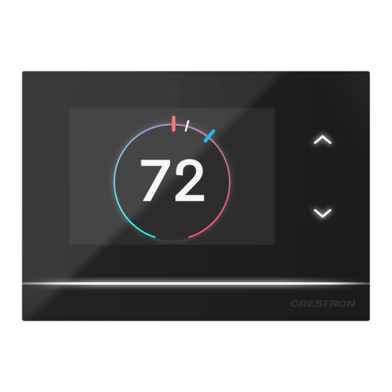
Page 153: Operation
Operation The HZ-THSTAT has a 3.5 in. LCD touch screen display used for configuring the thermostat to the HVAC system and monitoring the temperature and humidity. Overview The images below provide a general overview of common user interface elements on the HZ-THSTAT during normal operation. - Page 154 User Interface - System Controls User Interface - Error Icons Product Manual — Doc. 8622E HZ-THSTAT • 154...
- Page 155 User Interface - Short Cycle Message User Interface - Wireless Disconnected 155 • HZ-THSTAT Product Manual — Doc. 8622E...
- Page 156 The images above represent the UI of a white (-W) thermostat in day mode. The Almond (-A) and Black (-B) thermostats have Almond and Dark themes, respectively. In night mode, White and Almond thermostats switch to a dark theme and appear as shown below. Product Manual —...
-
Page 157: Lightbar And Up And Down Buttons
Lightbar and Up and Down Buttons Use the Up/Down buttons to change the heat and cool setpoints and to access the Installer Settings. In Dual Setpoint mode, the thermostat attempts to assume which setpoint the user is adjusting when pressing the up or down button. To adjust a different setpoint, use the setpoint handle on the touch screen to assign the setpoint, or tap a setpoint handle to select it and then use the up and down buttons to assign the setpoint. -
Page 158: Weather
Weather Once connected to a Wi-Fi network and the location data is set on the Location on page 172 screen, the weather icon reports the outdoor temperature. Tap the weather icon to open the current forecast and three days out of the ten-days forecast. Swipe right to left to scroll through the remaining six days. Side Menu The Side menu provides the end user access to system controls. -
Page 159: System Modes
System Modes Select Mode and then the desired Mode for the configured system. Cool: To control the cooling system. Heat: To control the heating system. Aux Heat: (only for Heat Pump systems) To shut off the Heat Pump and force heat only mode using the Auxiliary Heat stages. -
Page 160: Fan Modes
Fan Modes Select FAN and then the desired mode for the Fan operation. Fan Selections for Systems with One Fan Speed Fan Selections for Systems with Multiple Fan Speeds Auto: Turns on the fan automatically when the system is operating. Select Auto to enable cool or heat calls and Fan In Heat settings to turn on the fan automatically. -
Page 161: Humidity Control
Humidity Control Select HUMIDITY to turn the Humidistat on or off. Either Humidify or Dehum (dehumidify) will show depending on whether Humidification of Dehumidification is set in Humidistat Setup. If Humidistat Setup is set to Off in the Installer Settings, the humidity controls will not be displayed. To show or hide HUMIDITY in the Side menu, refer to End User Access on page 170. -
Page 162: Brightness
Brightness NOTE: Set the thermostat's autodim curve by adjusting the slider for the desired brightness in both a dim room condition and a full dark condition. Adjusting in a dim room ensures that the thermostat's local sensor is not saturated and accurately adjusts the dim curve. -
Page 163: User Settings
User Settings To open the SETTINGS screen: 1. Swipe up from the bottom of the screen. 2. Tap the gear icon. 3. Tap Display or Wireless Network to adjust the settings. These are easy-to-access settings for the end user. Refer to Display on page 164and Wireless Network on page 166... -
Page 164: Display
Display Use the DISPLAY screens to adjust the display and backlight settings for both day and night themes. The thermostat's local sensor determines day and night based on the ambient light level. When the sensor detects low light levels, the thermostat switches to the night theme. NOTES: The Help icon ( ) provides descriptions of settings throughout the setup screens. - Page 165 Timeout Behavior: The desired behavior for when the thermostat times out. Select Reduced Info, Display Off, and All Off. Reduced Info: Removes extra items on the screen for a clean look. Display Off: Turns off the screen and the Up/Down buttons. The lightbar indicates All Off: Turns off the screen, the Up/Down buttons, and the lightbar.
-
Page 166: Wireless Network
Wireless Network The WIRELESS NETWORK provides quick access to limited network settings and information. For more wireless network settings, refer to Installer Settings on page 168. Wireless Networks Use the Wireless Networks screen to display the available networks. To update the list of networks, selectRefresh. To join a wireless network: 1. - Page 167 4. Tap Join Network. Wireless Network Info Use the Wireless Network Info screen to display the following data: MAC Address, IP Address, Subnet Mask, Def Router, Primary DNS, Secondary DNS, Hostname, Domain, RSSI, and LQI. Manage Saved Networks Use the Manage Saved Networks to display and edit the saved networks. Tap on a listed network to set it as the preferred network, change the password, or delete the network.
-
Page 168: Installer Settings
Installer Settings Use the Installer Settings screens to configure the thermostat. To open the INSTALLER SETTINGS screen: 1. Swipe up from the bottom of the screen and then tap the gear icon. 2. Use the Up/Down buttons to enter the Installer Settings button sequence. Tap the Up button two times and then the Down button two times (Up, Up, Down, Down). -
Page 169: Product Manual
3. The INSTALLER SETTINGS screen displays. Product Manual Select PRODUCT MANUAL to display a QR code that opens this Product Manual. Scan the QR code with a smart device. 169 • HZ-THSTAT Product Manual — Doc. 8622E... -
Page 170: System Configuration
System Configuration Use the System Configuration screen to configure the System Type, System Performance, Radiant Floor, User Controls, Humidistat, and Sensors to work with the connected HVAC system. For details, refer to Configuration on page To configure a specific system type, refer to these sections of the Configuration on page 45 section. -
Page 171: Wireless Network
Wireless Network Provides the same settings as the end user Wireless Network screen but also includes IP Settings and IP Table Setup. For details, refer to Wireless Network on page 166. IP Settings Use the IP Settings screen to switch between DHCP and static IP, and manually set the host name and static IP settings. -
Page 172: Location
IP Table Setup allows the thermostat to be connected to a control system. An IP Table is a lookup table used by Crestron Ethernet devices to map between IP IDs and IP addresses. Refer to the control system documentation for details. -
Page 173: Diagnostics
Diagnostics Use DIAGNOSTICS to test the HVAC system calls, review call log summaries, sensor log summaries, or review system settings. Test Call Use the Test Call screen to view the test call options. The system type and configured settings determine the available test call options Tap the toggle next the desired option to perform a test call. -
Page 174: About
Sensor Summary Use the Sensor Summary screen to view details about the local and remote sensors. As with Min/Max/Average temperature/humidity and error counts, information can be filtered by Day, Week, or Month and specific days, weeks, or months. System Overview Use the System Overview screen to view a summary of the system configuration. -
Page 175: Glossary
Glossary The following are system type and radiant floor definitions. System Type Definitions One or Two Stage Heat/Cool Systems Unlike traditional furnaces that turn on and run at full capacity with each demand for heating, 2-stage furnaces operate like two separate furnaces. The unit begins to run in its first stage, and operates at a fraction of its heating capacity. -
Page 176: Radiant Floor Heating Definitions
Radiant Floor Heating Definitions Radiant floor heating works from the ground up. The heating components are installed below the floor or are embedded in a concrete slab. Heat radiates from the floor to warm the space above. Floor Warming: Operates the radiant floor heat to maintain a particular floor temperature. Floor Warming can be turned on and off by the end user. - Page 177 1 Stage Heat (Radiant Floor)/2 Stage Cool 2-Pipe FCU Cool Only: Maintains the air temperature using the radiant floor for heat, up to the radiant floor maximum. Cools the space with cooling FCU call. Radiant floor heat on terminal W2, space cool on terminals Y/Y2, and High/Med/Low Fan speeds on O/B/G.
- Page 178 This page is intentionally left blank. Product Manual — Doc. 8622E HZ-THSTAT • 178...
- Page 179 Crestron Electronics, Inc. Product Manual — Doc. 8622E 15 Volvo Drive, Rockleigh, NJ 07647 11/15/23 Tel: 888.CRESTRON Specifications subject to Fax: 201.767.7656 change without notice. www.crestron.com...
Need help?
Do you have a question about the Horizon HZ-THSTAT and is the answer not in the manual?
Questions and answers