YASKAWA VS-606V7 Series Instruction Manual
Compact general-purpose inverter (voltage vector control)
Hide thumbs
Also See for VS-606V7 Series:
- Instruction manual (176 pages) ,
- Instruction manual (176 pages) ,
- Connection manual (64 pages)
Table of Contents
Advertisement
Quick Links
Advertisement
Table of Contents

Related Manuals for YASKAWA VS-606V7 Series


Summary of Contents for YASKAWA VS-606V7 Series
-
Page 1: Instruction Manual
YASKAWA VS-606V7 Series INSTRUCTION MANUAL COMPACT GENERAL-PURPOSE INVERTER (VOLTAGE VECTOR CONTROL) Upon receipt of the product and prior to initial operation, read these instructions thoroughly and retain them for future reference. YASKAWA MANUAL NO. TOE-S606-11.2H... -
Page 2: General Precautions
PREFACE Yaskawa’s VS-606V7 is a small and simple Inverter; as easy to use as a contactor. This instruction manual describes installation, maintenance, inspection, troubleshooting, and specifications of the VS-606V7. Read this instruction manual thoroughly before operation. YASKAWA ELECTRIC CORPORATION General Precautions •... -
Page 3: Notation For Safety Precautions
NOTATION FOR SAFETY PRECAUTIONS Read this instruction manual thoroughly before installation, operation, mainte- nance, or inspection of the VS-606V7. In this manual, safety precautions are classified as either warnings or cautions and are indicated as shown below. WARNING Indicates a potentially hazardous situation which, if not avoided, may result in death or serious injury. - Page 4 PRECAUTIONS FOR UL/cUL MARKING • Do not connect or disconnect wiring, or perform signal checks while the power supply is turned ON. • The Inverter internal capacitor is still charged even after the power supply is turned OFF. To prevent electric shock, disconnect all power before ser- vicing the Inverter, and then wait at least one minute after the power sup- ply is disconnected.
- Page 5 RECEIVING THE PRODUCT CAUTION (Ref. page) • Do not install or operate any Inverter that is damaged or has missing parts. Failure to observe this caution may result in injury or equipment damage. MOUNTING CAUTION (Ref. page) • Lift the Inverter by the heatsinks. When moving the Inverter, never lift it by the plastic case or the terminal cover.
- Page 6 WIRING WARNING (Ref. page) • Only begin wiring after verifying that the power supply is turned OFF. Failure to observe this warning may result in an elec- tric shock or a fire. • Wiring should be performed only by qualified personnel.
- Page 7 CAUTION (Ref. page) • Verify that the Inverter rated voltage coincides with the AC power supply voltage. Failure to observe this caution may result in personal injury or a fire. • Do not perform a withstand voltage test on the Inverter.
- Page 8 OPERATION WARNING (Ref. page) • Only turn ON the input power supply after con- firming that the Digital Operator or blank cover (optional) are in place. Do not remove the Digital Operator or the covers while current is flowing. Failure to observe this warning may result in an elec- tric shock.
- Page 9 WARNING (Ref. page) • If an alarm is reset with the operation signal ON, the Inverter will restart automatically. Reset an alarm only after verifying that the operation sig- nal is OFF. Failure to observe this warning may result in injury. •...
- Page 10 CAUTION (Ref. page) • If using an Inverter with an elevator, take safety measures on the elevator to prevent the eleva- tor from dropping. Failure to observe this caution may result in injury. • Do not perform signal checks during operation. The machine or the Inverter may be damaged.
- Page 11 MAINTENANCE AND INSPECTION WARNING (Ref. page) • Never touch high-voltage terminals on the Inverter. Failure to observe this warning may result in an elec- trical shock. • Disconnect all power before performing mainte- nance or inspection, and then wait at least one minute after the power supply is disconnected.
- Page 12 CAUTION (Ref. page) • The control PCB employs CMOS ICs. Do not touch the CMOS elements. They are easily damaged by static electricity. • Do not connect or disconnect wires, connectors, or the cooling fan while power is applied to the circuit.
-
Page 13: Warning Label
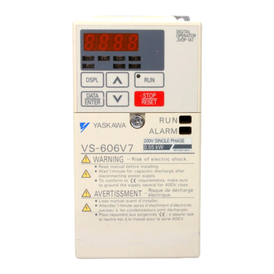
WARNING LABEL A warning label is provided on the front cover of the Inverter, as shown below. Follow the warnings when handling the Inverter. Top Cover (in case of 5.5/7.5 kW) Plastic Case Status Indicators Nameplate Warning Label Location Warning Labels Example of 5.5 kW for 400 V... -
Page 14: Warranty Information
Repairs If a Yaskawa product is found to be defective due to Yaskawa workman- ship or materials and the defect occurs during the warranty period, Yaskawa will provide a replacement, repair the defective product, and provide shipping to and from the site free of charge. - Page 15 Exceptions Any inconvenience to the customer or damage to non-Yaskawa products due to Yaskawa's defective products whether within or outside the war- ranty period are NOT covered by this warranty. RESTRICTIONS • The VS-606V7 was not designed or manufactured for use in devices or systems that may directly affect or threaten human lives or health.
-
Page 16: Table Of Contents
CONTENTS NOTATION FOR SAFETY PRECAUTIONS - - - - - - 2 1. Receiving the Product - - - - - - - - - - - - - - - - - - - 20 Checking the Nameplate - - - - - - - - - - - - - - - - - - - - - - - - - - - 21 2. - Page 17 Function Indicator Description- - - - - - - - - - - - - - - - - - - - - - - - 47 MNTR Multi-function Monitoring - - - - - - - - - - - - - - - - - - - - - - 48 Input/Output Terminal Status - - - - - - - - - - - - - - - - - - - - - - - - - 50 Data Reception Error Display - - - - - - - - - - - - - - - - - - - - - - - - 50 Simple Data Setting - - - - - - - - - - - - - - - - - - - - - - - - - - - - - - - 52...
- Page 18 Jump Frequencies (n083 to n086) - - - - - - - - - - - - - - - - - - - - 76 Continuing Operation Using Automatic Retry Attempts (n082) - - - - - - - - - - - - - - - - - - - - - - - - - - - - - - - - - - - - - - - - 77 Operating a Coasting Motor without Tripping - - - - - - - - - - - - - 77 Holding Acceleration/Deceleration Temporarily - - - - - - - - - - - 78 Using Frequency Meter or Ammeter (n066) - - - - - - - - - - - - - - 79...
- Page 19 Using Energy-saving Control Mode - - - - - - - - - - - - - - - - - - - 125 Energy-saving Control Selection (n139) - - - - - - - - - - - - - - - - 125 Energy-saving Search Operation- - - - - - - - - - - - - - - - - - - - - 126 Motor Code - - - - - - - - - - - - - - - - - - - - - - - - - - - - - - - - - - - - 129 Using PID Control Mode- - - - - - - - - - - - - - - - - - - - - - - - - - - 130...
- Page 20 8. Fault Diagnosis - - - - - - - - - - - - - - - - - - - - - - - 165 Protective and Diagnostic Functions - - - - - - - - - - - - - - - - - - 165 Corrective Actions of Models with Blank Cover - - - - - - - - - - 165 Corrective Actions of Models with Digital Operator - - - - - - - - 166 Troubleshooting - - - - - - - - - - - - - - - - - - - - - - - - - - - - - - - - 178...
-
Page 21: Receiving The Product
1. Receiving the Product Do not install or operate any Inverter that is damaged or CAUTION has missing parts. Failure to observe this caution may result in injury or equipment damage. After unpacking the VS-606V7, check the following. • Verify that the model number matches your purchase order or packing slip. -
Page 22: Checking The Nameplate
With Digital Operator (with potentiometer) 3.7 kW Without Digital Operator (with blank cover) 5.5 kW With Digital Operator (without potentiometer) 7.5 kW Note: Contact your Yaskawa representatives for models without heatsinks. Voltage Class Single-phase 200 VAC Three-phase 200 VAC Three-phase 400 VAC... -
Page 23: Identifying The Parts
2. Identifying the Parts Digital Operator Terminal Cover Wiring Holes for Control Circuit Front Cover Wiring Holes Nameplate for Main Circuit Heatsink Bottom Cover Ground Terminal Cooling Fan Fan Cover Digital operator Digital operator Blank cover (with potentiometer) (without potentiometer) In models without a JVOP-140 JVOP-147... - Page 24 2. Identifying the Parts VS-606V7 Inverters with the Covers Removed Frequency Setting Potentiometer Inverter Operation Status Indicators Terminal Resistor Switch for Input Polarity Communication Circuit Switch Voltage/Current Change Switch for Analog Frequency Reference Input Short-circuit Control Circuit Terminal Block Main Circuit Terminal Block Ground Terminals Example for 3-phase (200 V Class, 1.5 kW) Inverter Frequency Setting Potentiometer...
- Page 25 Main Circuit Terminal Arrangement The terminal arrangement of the main circuit terminals depends on the Inverter model. CIMR-V7∗T20P1 to 20P7, B0P1 to B0P4 CIMR-V7∗T21P5, 22P2, B0P7, B1P5, 40P2 to 42P2 CIMR-V7∗T23P7, B2P2, 43P0, 43P7 CIMR-V7∗TB3P7 CIMR–V7∗T25P5, 27P5, 45P5, 47P5 R/L1 S/L2 T/L3 B2 U/T1 V/T2 W/T3...
-
Page 26: Mounting
3. Mounting 3. Mounting Choosing a Location to Mount the Inverter Be sure the Inverter is protected from the following conditions. • Extreme cold and heat. Use only within the specified ambient tem- perature range: −10 to 50°C for IP20 (open chassis type), −10 to 40°C for NEMA 1 (TYPE 1) •... -
Page 27: Mounting Dimensions
Mounting Dimensions To mount the VS-606V7, the dimensions shown below are required. 100 mm or more 100 mm or more Max. Applicable Voltage Class Length a Motor Capacity (kW) 200 V Single-phase 3.7 kW or less 30 mm min. 3-phase 400 V 3-phase 5.5 kW 200 V 3-phase... -
Page 28: Mounting/Removing Components
3. Mounting • The same space is required horizontally and vertically and right and left for both Open Chassis (IP00, IP20) and NOTE Enclosed Wall-mounted (NEMA 1) Inverters. • Always remove the top and bottom covers before install- ing a 200 or 400 V Class Inverter with an output of 5.5/7.5 kW in a panel. -
Page 29: Mounting The Terminal Cover
• Inverters with Width of 180 Use a screwdriver to loosen the screw (section B) on the termi- nal cover surface. (This screw can not be removed to prevent loss.) Then press the right and left sides in direction 1 and lift the terminal cover in direction Mounting the Terminal Cover Mount the terminal cover by... -
Page 30: Removing The Bottom Cover
3. Mounting Removing the Bottom Cover • Inverters with Width of 108 mm, 140 mm or 170 mm After removing the front cover and the terminal cover, tilt the bottom cover in direction 1 with section A as a supporting point. -
Page 31: Wiring
4. Wiring • Only begin wiring after verifying that the power sup- WARNING ply is turned OFF. Failure to observe this warning may result in an electric shock or a fire. • Wiring should be performed only by qualified per- sonnel. - Page 32 4. Wiring emergency stop by using the external terminals. Delayed response may cause injury or damage the machine. Wiring Instructions NOTE 1. Always connect the power supply for the main circuit inputs to the power input terminals R/L1, S/L2, and T/L3 (R/L1, S/L2 for single-phase power) via a molded-case circuit breaker (MCCB) or a fuse.
-
Page 33: Wire And Terminal Screw Sizes
wire size. Voltage drop can be calculated using the following equa- tion: Phase-to-phase voltage drop (V) × wire resistance (Ω/km) × wiring distance (m) × current (A) × 10 Select a wire size so that voltage drop will be less than 2% of the normal rated voltage. - Page 34 4. Wiring 2. Main Circuits 200 V Class 3-phase Input Inverters Model Terminal Symbols Screws Tightening Wires Torque Applicable Size Recommended Type N•m Size CIMR- R/L1, S/L2, T/L3, M3.5 0.8 to 1.0 0.75 to 2 18 to 14 600 V vinyl- V7∗T -, +1, +2, B1, B2, sheathed or...
- Page 35 200 V Class Single-phase Input Inverters Model Terminal Symbols Screws Tightening Wires Torque Applicable Size Recommended Type N•m Size CIMR- R/L1, S/L2, T/L3, M3.5 0.8 to 1.0 0.75 to 2 18 to 14 600 V vinyl- V7∗T -, +1, +2, B1, B2, sheathed or B0P1 U/T1, V/T2, W/T3...
- Page 36 4. Wiring 400 V Class 3-phase Input Inverters Model Terminal Symbols Screws Tightening Wires Torque Applicable Size Recommended Type N•m Size CIMR- R/L1, S/L2, T/L3, 1.2 to 1.5 2 to 5.5 14 to 10 600 V vinyl- V7∗T -, +1, +2, B1, B2, sheathed or 40P2 U/T1, V/T2, W/T3...
-
Page 37: Wiring The Main Circuits
Wiring the Main Circuits [Example of 3-phase, 400 V class, 0.2 kW Inverters] MCCB or Leakage Breaker Grounding • Main Circuit Input Power Supply Always connect the power supply line to input terminals R/L1, S/L2, and T/L3 (R/L1, S/ L2 for single-phase Inverters). Never connect them to terminals U/T1, V/T2, W/T3, B1, B2, −, +1, or +2. - Page 38 4. Wiring • Braking Resistor Connection (Optional) To connect the braking resistor, cut the protector on terminals WARNING B1 and B2. To protect the braking resistor from overheating, install a ther- mal overload relay between the braking resistor and the Inverter.
-
Page 39: Wiring The Control Circuits
Wiring the Control Circuits Only basic insulation is provided for the control circuit terminals. Additional insulation may be necessary in the end product. • Control Circuit Terminals Pass the cable through wiring hole to connect it. Always mount the cover in its original position. Contact Output SW1 can be changed according to sequence input signal (S1 to S7) polarity. -
Page 40: Wiring Inspection
4. Wiring • Keep the screwdriver vertical to the Inverter. NOTE • Refer to Page 32 for tightening torques. 5.5 mm The wire sheath strip length must be 5.5 mm. Open the front cover and verify that the strip length is 5.5 mm. 5.5mm Scale CONTACT OUTPUT... -
Page 41: Operating The Inverter
5. Operating the Inverter The Control Mode Selection (n002) is initially set to V/f control mode. • Only turn ON the input power supply after confirm- WARNING ing that the Digital Operator or blank cover (optional) are in place. Do not remove the Digital Operator or the covers while current is flowing. -
Page 42: Test Run
5. Operating the Inverter Test Run The Inverter operates when a frequency (speed) is set. There are four operating modes for the VS-606V7: 1. RUN command from the Digital Operator (potentiometer/digital set- ting) 2. RUN command from the control circuit terminals 3. - Page 43 Operation Steps Operator Function Status Display Indicators Indicators 1. Turn the potentiometer fully counter- 0.00 FREF clockwise, and then turn the power ON. ALARM 2. F/R will lit. Select FOR or REV RUN using the (Forward) keys. ALARM Never select REV when reverse run is prohibited.
-
Page 44: Selecting Rotation Direction
5. Operating the Inverter Selecting Rotation Direction It is possible to select the direction in which the motor rotates when the FORWARD RUN command is executed. The motor rotates in the opposite direction when the REVERSE RUN command is executed. n040 Description Setting... -
Page 45: Operating The Digital Operator
Operating the Digital Operator All functions of the VS-606V7 are set using the Digital Operator. Below are descriptions of the display and keypad sections. JVOP-140 Digital Operator Data Display Section Indicator/Display Section Function Indicators Indicators switch to another function each time is pressed. -
Page 46: Description Of Status Indicators
5. Operating the Inverter Description of Status Indicators There are two Inverter operation status indicators on the middle right section of the face of the VS-606V7. The combinations of these indica- tors indicate the status of the Inverter (ON, flashing, and OFF). RUN indicator and status indicator on the button have the same func- tion. - Page 47 For details on how the status indicators function for Inverter faults, refer to Chapter 8. Fault Diagnosis. If a fault occurs, the ALARM indicator will lit. The fault can be reset by turning ON the FAULT RESET sig- NOTE nal (or by pressing the key on the Digital Operator) with the operation signal OFF, or by turning OFF the power supply.
-
Page 48: Function Indicator Description
5. Operating the Inverter Function Indicator Description By pressing on the Digital Operator, each of the function indi- cators can be selected. The following flowchart describes each function indicator. Power ON Frequency reference setting/monitoring (Hz) Sets VS-606V7 operating speed. Output frequency monitoring (Hz) Displays frequency that VS-606V7 is If the VS-606V7 loses currently outputting. -
Page 49: Mntr Multi-Function Monitoring
If the VS-606V7 is LOCAL/REMOTE Selection stopped after it has This function switches the operation; operation changed to any of using the Digital Operator including frequency setting with potentiometer, operation using the these modes during input terminals, or operation through communications. operation, it changes Setting can be changed using the key. - Page 50 5. Operating the Inverter Monitoring The following items can be monitored using U constants. Constant Name Unit Description U-01 Frequency Reference Frequency reference can be monitored. (Same as FREF) (FREF)* U-02 Output Frequency Output frequency can be monitored. (Same as FOUT) (FOUT)* U-03 Output current can be monitored.
-
Page 51: Input/Output Terminal Status
In vector control mode, “---” will be displayed. * 4. Applicable only for Inverters of 5.5 kW and 7.5 kW (200-V and 400-V Classes). * 5. Refer to the next page for data reception error. * 6. Displayed in units of 0.1% when less than 100% and in units of 1% when 100% or more. - Page 52 5. Operating the Inverter Fault History Display Method When U-09 is selected, a four-digit box is displayed. The three digits from the right show the fault description, and the digit on the left shows the order of fault (from one to four). Number 1 represents the most recent fault, and numbers 2, 3, 4 represent the other faults, in ascending order of fault occurrence.
-
Page 53: Simple Data Setting
Simple Data Setting Digital setting (refer to 5. Operating the Inverter) and potentiometer setting are both possible for simple acceleration/deceleration operation of the VS-606V7. Digital setting is set at the factory (n004=0). For the model with JVOP- 147 Digital Operator (without potentiometer), factory setting is set by frequency setting potentiometer (n004=1). - Page 54 5. Operating the Inverter Data setting by frequency setting potentiometer Operation Steps Operator Function Status Display Indicators Indicators 1. Turn ON the power supply. 0.00 FREF ALARM DSPL PRGM 2. Press to make lit, then PRGM set constant n004 to 1. ALARM 3.
-
Page 55: Programming Features
6. Programming Features Factory settings of the constants are shaded in the tables. After wiring is complete, be sure to make the following settings before oper- ation. Hardware Make the following settings before the Inverter is turned ON. Item Ref. Sequence input signal (S1 to S7) polarity selection Voltage reference / current reference input selection of control circuit terminal FR... -
Page 56: Constant Setup And Initialization
6. Programming Features Constant Setup and Initialization Constant Selection/Initialization (n001) If n001=5, a Run command can be received even WARNING while changing a constant. If sending a Run command while changing a constant, such as during a test run, be sure to observe all safety precautions. Failure to observe this warning may result in injury. - Page 57 appears on the display for one second and the set data NOTE returns to its initial values in the following cases. 1. If the set values of Multi-function Input Selections 1 to 7 (n050 to n056) are the same 2. If the following conditions are not satisfied in the V/f pat- tern setting: Max.
-
Page 58: Using V/F Control Mode
6. Programming Features Using V/f Control Mode V/f control mode is preset at the factory. Control Mode Selection (n002) = 0: V/f control mode (factory setting) 1: Vector control mode Adjusting Torque According to Application Adjust motor torque by using the V/f pattern and full-range automatic torque boost settings. - Page 59 Typical Setting of the V/f Pattern Set the V/f pattern according to the application as described below. For 400-V Class Inverters, the voltage values (n012, n015, and n017) should be doubled. When running at a frequency exceeding 50/60 Hz, change the Maximum Output Frequency (n011). Note: Always set the maximum output frequency according to the motor char- acteristics.
- Page 60 6. Programming Features Full-range Automatic Torque Boost (when V/f Mode is Selected: n002=0) The motor torque requirement changes according to load conditions. The full-range automatic torque boost adjusts the voltage of the V/f pat- tern according to requirements. The VS-606V7 automatically adjusts the voltage during constant-speed operation, as well as during accelera- tion.
-
Page 61: Using Vector Control Mode
1: Vector control mode Precautions for Voltage Vector Control Application Vector control requires motor constants. The Yaskawa standard motor constants have been set at the factory prior to shipment. Therefore, when a motor designed for an Inverter is used or when a motor from any... -
Page 62: Motor Constant Calculation
6. Programming Features • If the speed is less than the target value, increase the slip compensa- tion gain. • If the speed is more than the target value, reduce the slip compensa- tion gain. Adjustment of the Slip Compensation Time Constant (n112) is normally not required. -
Page 63: V/F Pattern During Vector Control
Set n106 (Motor Rated Slip), n036 (Motor Rated Current), n107 (Motor Line-to-neutral Resistance), and n110 (Motor No-load Current) accord- ing to the motor test report. To connect a reactor between the Inverter and the motor, set n108 to the sum of the initial value of n108 (Motor Leakage Inductance) and the externally mounted reactor inductance. -
Page 64: Switching Local/Remote Mode
6. Programming Features When operating with frequency larger than 60/50 Hz, change only the Max. Output Frequency (n011). Constant output or Constant torque variable output n012 =200 V Base point n013 n011 =60 or 50 Hz =90 Hz Switching LOCAL/REMOTE Mode The following functions can be selected by switching LOCAL or REMOTE mode. -
Page 65: How To Select Local/Remote Mode
How to Select LOCAL/REMOTE Mode When LOCAL/REMOTE When LOCAL/REMOTE switching function is not switching function is set set for multi-function for multi-function input input selection selection (When 17 is not set (When 17 is set for for any of constants any of constants n050 to n056) n050 to n056) -
Page 66: Remote Mode
6. Programming Features REMOTE Mode 1. Select remote mode. There are following two methods to select remote mode. • Select rE (remote mode) for the selection. • When the local/remote switching function is selected for the multi-function input selection, turn OFF the input terminal to select remote mode. -
Page 67: Local Mode
LOCAL Mode Select command method using constant n008. n008=0: Enables using the potentiometer on the Digital Operator (factory setting). The factory setting for models with the Digital Operator without a potentiometer (JVOP-147) is n008=1. =1: Enables digital setting on the Digital Operator. [Setting can be stored in Frequency Reference 1 (n024)]. -
Page 68: Setting Operation Conditions
6. Programming Features Setting Operation Conditions Reverse Run Prohibit (n006) The Reverse Run Prohibit setting disables accepting a reverse RUN command from the control circuit terminal or Digital Operator. This set- ting is used for applications where a reverse RUN command can cause problems. -
Page 69: Operating At Low Speed
(n031) 60.0 Hz (n030) 55.0 Hz (n029) 50.0 Hz (n028) 45.0 Hz (n027) 40.0 Hz (n026) 35.0 Hz (n025) 30.0 Hz Frequency (n024) 25.0 Hz reference Time FWD (REV) RUN/STOP Multi-step speed ref. 1 (terminal S5) Multi-step speed ref. 2 (terminal S6) Multi-step speed ref. -
Page 70: Adjusting Speed Setting Signal
6. Programming Features Adjusting Speed Setting Signal The relationship between the analog inputs and the frequency reference can be set to provide the frequency reference as analog inputs to control circuit terminal FR or FC. Frequency Reference ( ) indicates the value when a current (4 mA) (20 mA) reference input is selected. -
Page 71: Adjusting Frequency Upper And Lower Limits
• To operate the Inverter with a frequency reference of 50% to 100% at an input voltage of 0 to 10 V Max. frequency (100%) 10 V Gain n060 = 100 Bias n061 = 50 Adjusting Frequency Upper and Lower Limits •... - Page 72 6. Programming Features By setting a multi-function input selection (either of n050 to n056) to 11 (acceleration/deceleration time selection 1) or 27 (acceleration/deceler- ation time selection 2), the acceleration/deceleration time is selected by ON/OFF combinations of acceleration/deceleration time selection 1 and acceleration/deceleration time selection 2 (terminals S1 to S7).
-
Page 73: Momentary Power Loss Ridethrough Method (N081)
n018 Settings Unit Setting Range n018 0.1 s 0.0 to 999.9 s (999.9 s or less) 1000 to 6000 s (1000 s or more) 0.01 s 0.00 to 99.99 s (99.99 s or less) 0.1 s 100.0 to 600.0 s (100 s or more) Note: Constant n018 can be set while stopped. -
Page 74: S-Curve Selection (N023)
6. Programming Features * 1. Hold the operation signal to continue operation after recovery from a momentary power loss. * 2. When 2 is selected, the Inverter restarts if power supply voltage recovers while the control power supply is held. No fault signal is output. -
Page 75: Torque Detection
Torque Detection If an excessive load is applied to the machine, an increase in the output current can be detected to output an alarm signal to multi-function out- put terminal MA, MB, P1, or P2. To output an overtorque detection signal, set one of the output terminal function selections n057 to n059 for overtorque detection (Setting: 6 (NO contact) or 7 (NC contact)). -
Page 76: Frequency Detection Level (N095)
6. Programming Features 3. To stop the Inverter and generate a fault at overtorque detection, set n096 to 2 or 4. At detection, the Digital Operator will display an fault (ON). Overtorque Detection Level (n098) Set the overtorque detection current level in units of 1%. (Inverter rated current = 100%) When detection by torque is selected, the motor rated torque becomes 100%. -
Page 77: Jump Frequencies (N083 To N086)
Frequency Detection 1 Output frequency ≥ Frequency Detection Level n095 (Set n057, n058 or n059 to 4.) Release Width −2Hz Frequency Detection Level [Hz] (n095) Output Frequency Frequency Detection Signal Frequency Detection 2 Output frequency ≤ Frequency Detection Level n095 (Set n057, n058 or n059 to 5.) Release Width... -
Page 78: Continuing Operation Using Automatic Retry Attempts
6. Programming Features Continuing Operation Using Automatic Retry Attempts (n082) When the fault retry function is selected, stand clear of WARNING the Inverter or the load. The Inverter may restart sud- denly after stopping. (Construct the system to ensure safety, even if the Inverter should restart.) Failure to observe this warn- ing may result in injury. -
Page 79: Holding Acceleration/Deceleration Temporarily
Timechart at SEARCH Command Input FWD (REV) RUN Command 0.5 s Min. SEARCH Command Speed Agreement Max. Output Frequency or Detection Frequency Reference at Run Command Input Output Frequency Min. Baseblock Speed Time (0.5 s) Search Operation The deceleration time for speed search operation can be set in n101. If the setting is 0, however, an initial value of 2.0 s will be used. -
Page 80: Using Frequency Meter Or Ammeter (N066)
6. Programming Features Timechart for ACCELERATION/DECELERATION HOLD Command Input FWD (REV) RUN Command ACCELERATION/ DECELERATION HOLD Command Frequency Reference Output Frequency FREQUENCY AGREE Signal Note: If a FWD (REV) RUN command is input at the same time as an ACCELERATION/DECELERATION HOLD command, the motor will not operate. -
Page 81: Calibrating Frequency Meter Or Ammerter (N067)
In factory setting, analog voltage of approx. 10 V is output when output frequency (output current) is 100 %. Output Frequency (Output Current) Frequency Meter 100 % Analog monitor gain can be set by n067. 10 V Analog Output Calibrating Frequency Meter or Ammerter (n067) Used to adjust analog output gain. - Page 82 6. Programming Features n065 Setting n065 Setting Description Analog monitor output Pulse monitor output (Output frequency monitor) Pulse train signal can be selected by setting in n150. n150 Setting Description Output 1440 Hz/Max. frequency (n011) frequency 1F: Output frequency × 1 monitor 6F: Output frequency ×...
- Page 83 Peripheral devices must be connected according to the fol- lowing load conditions when using pulse monitor output. NOTE The machine might damage when the conditions are not satis- fied. Used as a Sourcing Output Output Voltage Load Impedance Load VRL (V) (kΩ) Impedance +5 V...
-
Page 84: Reducing Motor Noise Or Leakage Current Using Carrier Frequency Selection (N080)
6. Programming Features Reducing Motor Noise or Leakage Current Using Carrier Fre- quency Selection (n080) Set the Inverter output transistor switching frequency (carrier fre- quency). Setting Carrier Frequency (kHz) Metallic Noise and Noise from Current Motor Leakage 12 fout (Hz) 24 fout (Hz) Higher 36 fout (Hz) - Page 85 If the set value is 7, 8, or 9, the carrier frequency will be multiplied by the same factor as the output frequency. n080=7 fc=Carrier Frequency 2.5 kHz fc=12 fout 1.0 kHz fout=Output Frequency 83.3 Hz 208.3 Hz n080=8 fc=Carrier Frequency 2.5 kHz fc=24 fout 1.0 kHz...
- Page 86 6. Programming Features Voltage Capacity Factory Setting Maximum Reduced Class (V) (kW) Continuous Current Setting Carrier Frequency Output Current (kHz) 200 V Single- phase or 3-phase 400 V 3-phase 0.75 14.8 * Reduction of the current is not necessary. 1. Reduce the continuous output current when changing the NOTE carrier frequency to 4 (10 kHz) for 200 V Class (1.5 kW or more) and 400 V Class Inverters.
-
Page 87: Operator Stop Key Selection (N007)
2. If the wiring distance is long, reduce the Inverter carrier frequency as described below. Wiring Distance Up to 50 m Up to 100 m More than 100 m between Inverter and Motor Carrier Fre- 10 kHz or less 5 kHz or less 2.5 kHz or less quency (n080 (n080=1, 2, 3, 4,... -
Page 88: Selecting The Stopping Method
6. Programming Features Set the processing when the STOP key is pressed during operation either from a multi-function input terminal or communications. Setting Description The STOP key is effective either from a multi- function input terminal or communications. When the STOP key is pressed, the Inverter stops ac- cording to the setting of constant n005. -
Page 89: Applying Dc Injection Braking
ates because the frequency reference is set lower than the Min. Output Frequency (n016) when the FWD (REV) RUN command is ON. If the deceleration time is short or the load inertia is large, an overvoltage (OV) fault may occur at deceleration. In this case, increase the decelera- tion time or install an optional Braking Resistor. - Page 90 6. Programming Features n016 Min. Output Frequency n090 DC Injection Braking Time at Stop When coasting to a stop is specified in the Stopping Method Selection (n005), DC injection braking is not applied when stopping.
-
Page 91: Building Interface Circuits With External Devices
Building Interface Circuits with External Devices Using Input Signals The functions of multi-function input terminals S1 to S7 can be changed as necessary by setting constants n050 to n056. The same value cannot be set for more than one of these constants. Setting Name Description... - Page 92 6. Programming Features Setting Name Description Ref. ACCELERATION/ DECELERATION HOLD command LOCAL/REMOTE selection Communications/control cir- cuit terminal selection Emergency stop fault, Inverter stops for an emergen- NO contact input cy stop signal input according to the Stopping Method Selec- Emergency stop alarm, tion (n005).
- Page 93 Factory Settings Terminal Factory Setting Function n050 FORWARD RUN command (2-wire sequence) n051 REVERSE RUN command (2-wire sequence) n052 External fault (NO contact input) n053 Fault reset n054 Multi-step speed reference 1 n055 Multi-step speed reference 2 n056 JOG command Terminal Functions for 3-wire Sequence Selection When 0 is set for terminal S3 (n052), terminal S1 is the RUN command, terminal S2 is the STOP command, and terminal S3 is the FWD/REV...
- Page 94 6. Programming Features Example: Set n003=1, n004=2, n008=0. Open: Run according to the frequency reference from multi-function input terminal FR and RUN command from multi-function input terminals S1 to S7. Closed: Run according to the potentiometer frequency reference and RUN command from the Digital Operator. UP/DOWN Commands (Setting: n056 = 34) When the FWD (REV) RUN command is ON, acceleration/deceleration is enabled by inputting the UP or DOWN signal from multi-function...
-
Page 95: Using The Multi-Function Analog Inputs (N077, N078, N079)
Note: 1. When UP/DOWN commands are selected, the upper limit speed is set regardless of frequency reference. Upper limit speed = Maximum Output Frequency (n011) × Frequency Reference Upper Limit (n033)/100 2. Lower limit value is either the Minimum Output Frequency (n016) or the Frequency Reference Lower Limit (n034) (whichever is larger.). - Page 96 6. Programming Features Multi-function Input Selection (n077) Name Unit Setting Factory Range Setting n077 Multi-function Input Selection 0 to 4 n077 Settings Setting Function Description Disabled The multi-function input is disabled. Auxiliary frequency When frequency reference 2 is select- reference (FREF2) ed using the multi-step speed referenc- es, the input analog signal for the CN2 terminal will be the frequency refer-...
- Page 97 Analog Input Level 1. Auxiliary Frequency Reference 2. Frequency Reference Gain (n077=1) (n077=2) FREF2 FGAIN 100% 2.00 1.00 10 V 10 V (4 mA) (20 mA) (4 mA) (20 mA) 100%=Max. Output Frequency (n011) 3. Frequency Reference Bias (n077=3) 4. Output Voltage Bias (n077=4) VBIAS FBIAS 100 V...
-
Page 98: Using Output Signals (N057, N058, N059)
6. Programming Features Using Output Signals (n057, n058, n059) The functions of multi-function output terminals MA, MB, P1 and P2 can be changed as necessary by setting constants n057, n058, and n059. • Terminal MA and MB functions: Set in n057 •... - Page 99 Setting Name Description Ref. Reverse run Closed during reverse run. Speed search Closed when Inverter conducts a speed search. Data output from com- Operates multi-function output termi- munications nal independently from Inverter opera- tion (by MEMOBUS communication) PID feedback loss Closed during PID feedback loss Frequency reference Closed during frequency reference loss...
-
Page 100: Setting Frequency By Current Reference Input
6. Programming Features Setting Frequency by Current Reference Input When setting frequency by input- ting current reference (4-20 mA or 0-20 mA) from the control circuit terminal FR, switch the DIP switch SW2 on the control circuit board to “I” side. Never input voltage reference to control circuit terminal FR NOTE when DIP switch SW2 is switched to “I”... - Page 101 Current Reference Selection After changing DIP switch (V-I switch of SW2) to the “I” side, press on the Digital Operator, then set the following constants. PRGM Current reference (4 to 20 mA)..constant n004 = 3 Current reference (0 to 20 mA)..constant n004 = 4 •...
-
Page 102: Frequency Reference By Pulse Train Input
6. Programming Features Frequency Reference by Pulse Train Input Frequency reference can be set by pulse train input from the control cir- cuit terminals. • Input pulse specifications • Low-level voltage: 0.8 V or less • High-level voltage: 3.5 to 13.2 V •... -
Page 103: Preventing The Motor From Stalling (Current Limit)
Preventing the Motor from Stalling (Current Limit) This function automatically adjusts the output frequency and output cur- rent according to the load to continue operation without stalling the motor. Stall Prevention (Current Limit) Level during Acceleration (n093) Sets the stall prevention (current limit) level during acceleration in units of 1%. - Page 104 6. Programming Features In the constant output area (output frequency > Max. Voltage Output Frequency (n013)), the stall prevention (current limit) level during acceleration is automatically decreased using the following equa- tion. Stall prevention (current limit) level during acceleration in constant output area Max.
-
Page 105: Stall Prevention During Operation
Motor Current Decreases frequency to prevent the motor from stalling. n094 At start of acceleration, the output current hysterisis is approx. 5% of Inverter rated Time current. Output Frequency 100 ms Time Stall Prevention during Operation Stall Prevention Above Base Speed During Run (n115) The stall prevention level can be decreased automatically in the constant output range. - Page 106 6. Programming Features Acceleration/Deceleration Time Selection during Stall Pre- vention (n116) With this function, Acceleration Time 2 (n021) and Deceleration Time 2 (n022) can be fixed as the acceleration/deceleration time when moving to prevent stalling during operation. Constant Name Unit Setting Factory Range...
-
Page 107: Decreasing Motor Speed Fluctuation
Decreasing Motor Speed Fluctuation Slip Compensation (n002 = 0) As the load becomes larger, the motor speed is reduced and the motor slip value is increased. The slip compensating function controls the motor speed at a constant value even if the load varies. When the Inverter output current is equal to the Motor Rated Current (n036), the compensation frequency is added to the output frequency. -
Page 108: Motor Protection
6. Programming Features Motor Protection Motor Overload Detection The VS-606V7 protects against motor overload with a built-in electonic thermal overload relay. Motor Rated Current (Electronic Thermal Reference Current, n036) Set the rated current value shown on the motor nameplate. Note: Setting n036 to 0.0 A disables the motor overload protective function. Motor Overload Protection Selection (n037, n038) n037 Electronic Thermal Characteristics... - Page 109 Example for 200 V-Class Motors Cooling Effect Torque Characteristics Electronic Thermal Over- load Effective when operated at ror (motor over- 60 s 50/60 Hz from Short-term load protection) commercial occurs when Continuous Torque rating power supply continuously operated at 50/ 60 Hz or less at 100% load.
-
Page 110: Selecting Cooling Fan Operation
6. Programming Features Selecting Cooling Fan Operation In order to increase the life of the cooling fan, the fan can be set to oper- ate only when Inverter is running n039 = 0 (Factory setting): Operates only when Inverter is running (Continues operation for 1 minute after Inverter is stopped.) Operates with power ON... -
Page 111: Communications Specified
Communications specified Interface RS-422, RS-485 Synchronization Asynchronous (Start-stop synchronization) Communication Baud rate: Selected from 2400/4800/9600/19200 bps Parameters Data length: 8 bits fixed Parity: Selected from even/odd/none Stop bits: 1 bit fixed Communication MEMOBUS (MODBUS) (RTU mode only) Protocol Max. Number of 31 units (When using RS-485) Inverters that Can be Connected... -
Page 112: Setting Constants Necessary For Communication
6. Programming Features Procedure for Communications with PLC The following shows the procedure for communications with PLC. 1. Connect the communication cable between the PLC and the VS- 606V7 with the power supply turned OFF. 2. Turn the power ON. 3. -
Page 113: Message Format
Constant Name Description Factory Setting n153 MEMOBUS Slave Setting range: 0 to 32* Address n154 MEMOBUS BPS 0: 2400 bps Selection 1: 4800 bps 2: 9600 bps 3: 19200 bps n155 MEMOBUS Parity 0: Even parity Selection 1: Odd parity 2: No parity n156 Transmission... - Page 114 6. Programming Features • Function code: Command codes (See below.) Func- Function Reference Message Response Message tion Code Minimum Maximum Minimum Maximum Hexa- (Byte) (Byte) (Byte) (Byte) decimal Reading holding register contents Loop back test Write in several holding registers •...
- Page 115 (Example) Reads out status signal, fault contents, data link status and frequency reference from the VS-606V7 (slave 2). Response Message Response Message Reference Message (at normal operation) (at fault occurrence) Slave address Slave address Slave address Function code Function code Function code Upper Number of data*...
- Page 116 6. Programming Features • Writing to Several Holding Registers (10H) Specified data are written into the several specified holding registers from the specified number, respectively. Written data must be arranged in a reference message in the order of the holding register numbers: from upper eight bits to lower eight bits.
- Page 117 Data • Reference Data (available to read out/write in) Register Description 0000H Reserved RUN command 1: Run 0: Stop Reverse run 1: Reverse run 0: Forward run External fault 1: Fault (EFO) Fault reset 1: Reset command Multi-function input reference 1 (Function selected by n050) Multi-function input reference 2 (Function selected by n051) 0001H Multi-function input reference 3 (Function selected by n052)
- Page 118 6. Programming Features • Simultaneous Broadcasting Data (available only for write in) Register Description RUN command 1: Run 0: Stop Reverse run 1: Reverse run 0: Forward run (Not used) 0001H (Not used) External fault 1: Fault (EFO) Fault reset 1: Fault reset command (Not used) Frequency reference 30000/100 % fixed unit...
- Page 119 Register Description Overcurrent (OC) Overvoltage (OV) Inverter overload (OL2) Inverter overheat (OH) (Not used) (Not used) PID feedback loss (FbL) External fault (EF, EFO), Emergency stop (STP) 0021H Hardware fault (FXX) Motor overload (OL1) Overtorque detection (OL3) Undertorque detection (UL3) Power loss (UV1) Control power fault (UV2) MEMOBUS communications timeover (CE)
- Page 120 6. Programming Features Register Description (Not used) (Not used) 0029H Input open phase (PF) Output open phase (LF) (Not used) Operation function stop (STP) Sequence error (SER) Simultaneous FWD/REV run commands (EF) External baseblock (BB) Overtorque detection (OL3) Cooling fan overheat (OH) Main circuit overvoltage (OV) Main circuit undervoltage (UV) 002AH...
- Page 121 Register Description 1: Run Zero-speed 1: Zero-speed Frequency agreed 1: Agreed Minor fault (Alarm is indicated) 1: Output frequency ≤ (n095) Frequency detection 1 1: Output frequency ≥ (n095) Frequency detection 2 Inverter operation ready 1: Ready Undervoltage detection 1: Undervoltage detection Baseblock 1: Inverter output baseblock 002CH...
-
Page 122: Storing Constants [Enter Command] (Can Be Written Only.)
6. Programming Features Register Description PID feedback value (100 % /Input equivalent to max. output frequency ; 0038H 10/1 % ; without sign) 0039H PID input value (±100 %/±Max. output frequency ; 10/1 % ; with sign) 003AH PID output value (±100 %/±Max. output frequency ; 10/1 % ; with sign) 003BH- Reserved 003CH... - Page 123 While the constant is being stored after an ENTER CAUTION command was issued, response to the commands or data input with the keys on the Digital Operator (JVOP-140) becomes poor. Be sure to take some mea- sures for an emergency stop by using the external ter- minals (setting the external terminal to run command priority, or setting the multi-function input terminal to external fault, external baseblock or emergency stop).
-
Page 124: Error Code
6. Programming Features Error code Error Contents Code Function code error • Function code from PLC is other than 03H, 08H, or 10H. Improper register number • No register numbers to be accessed have been registered. • ENTER command “0900H” that is an exclusive-use register for write-in was read out. -
Page 125: Performing Self-Test
Performing Self-test VS-606V7 is provided with a function to perform self-diagnosis for operation check of the serial communication I/F circuit. This function is called self-test. In the self-test, connect the sending terminal with the receiving terminal in the communication section. It assures if the data received by VS-606V7 is not being changed. -
Page 126: Using Energy-Saving Control Mode
The greater the enegy-saving coefficient is, the greater the output volt- age becomes. When using a motor other than a Yaskawa standard motor, set the motor code corresponding to the voltage and capacity in n158. Then, change the setting of the energy-saving coefficient K2 (n140) by 5% to mini- mize the output power. -
Page 127: Energy-Saving Search Operation
Energy-saving Voltage Lower/Upper Limits (n141, n142, n159, n160) Set the upper and lower limits of the output voltage. When the value calculated in the energy-saving control mode is larger than the upper limit (or smaller than the lower limit), the limit value is output as the voltage reference. - Page 128 6. Programming Features Search Operation Voltage Limit (n144) Limits the range where the voltage is controlled. The constant is set in % for 200-V/400-V Inverters. The search operation is not performed when n144 is set to 0. Constant Name Unit Setting Factory Range...
- Page 129 Search Operation Power Detection Hold Width (n161) When the power fluctuation is less than this value, the output voltage is held for 3 seconds, and then, the search operating mode is started. Set the hold width as a percentage of the power that is currently held. Constant Name Unit...
-
Page 130: Motor Code
The Energy-saving Coefficient K2 (n140) is set to a value that corre- sponds to the Motor Code (n158). Motor Type Voltage Capacity Motor Code: Energy-saving Class n158 Coefficient K2: n140 Yaskawa 200 V 0.1 kW 481.7 General- 0.2 kW 356.9 purpose Motor 0.4 kW 288.2... -
Page 131: Using Pid Control Mode
Motor Type Voltage Capacity Motor Code: Energy-saving Class n158 Coefficient K2: n140 Yaskawa 200 V 0.1 kW 481.7 Inverter 0.2 kW 356.9 Motor 0.4 kW 300.9 0.75 kW 224.7 1.5 kW 160.4 2.2 kW 138.9 3.7 kW 106.9 5.5 kW 84.1... -
Page 132: Pid Control Selection (N128)
6. Programming Features PID Control Selection (n128) Constant Name Unit Setting Factory Range Setting n128 PID Control Selection 0 to 8 Setting Function PID Output Characteristics Disabled. Enabled: Deviation is subject to derivative control. Forward Enabled: Feedback signal is subject to derivative control. Enabled: Frequency reference + PID output, and devia- tion are subject to derivative control. - Page 133 n164 Setting Description Control circuit terminal FR (Voltage 0 to 10 V) Control circuit terminal FR (Current 4 to 20 mA) Control circuit terminal FR (Current 0 to 20 mA) Operator terminal: Voltage 0 to 10 V Operator terminal: Current 4 to 20 mA Pulse train Note: 1.
- Page 134 6. Programming Features Proportional Gain (P), Integral Time (I), Derivative Time (D) (n130, n131, n132) Adjust the response of the PID control with the proportional gain (P), integral time (I), and derivative time (D). Constant Name Unit Setting Factory Range Setting n130 Proportional Gain (P)
- Page 135 Primary Delay Time Constant for PID Output (n135) Constant Name Unit Setting Factory Range Setting n135 Primary Delay Time 0.1 s 0.0 to 10.0 Constant for PID Out- Constant n135 is the low-pass filter setting for PID control outputs. There is normally no need to change the setting. If the viscous friction of the mechanical system is high or if the rigidity is low causing the mechanical system to resonate, increase the setting so that it is higher than the resonance frequency period.
- Page 136 6. Programming Features PID Feedback Loss Detection (n136, n137, n138) Constant Name Unit Setting Range Factory Setting n136 Selection for PID 0: No detection of Feedback Loss De- PID feedback loss tection 1: Detection of PID feedback loss, operation contin- ued: FbL alarm 2: Detection of PID feedback loss,...
- Page 138 6. Programming Features...
-
Page 139: Using Constant Copy Function
Using Constant Copy Function Constant Copy Function The VS-606V7 standard JVOP-140 Digital Operator can store constants for one Inverter. A backup power supply is not necessary because EEPROM is used. The constant copy function is possible only for the Inverters with the same product series, power supply specifications, and control mode (V/ f control or vector control). - Page 140 6. Programming Features Constant Name Unit Setting Range Factory Setting n176 Constant rdy: READY Copy Func- rEd: READ tion Selection CPy: COPY vFy: VERIFY vA: Inverter capacity display Sno: Software No. display Prohibiting Constant Read Selection (n177) Select this function to prevent accidentally overwriting the constants stored in EEPROM in the Digital Operator.
-
Page 141: Read Function
READ Function Reads out the constants in batch from the Inverter and stores them in EEPROM inside the Digital Operator. When the read-out is executed, the previously stored constants data in the EEPROM are cleared and replaced with the newly entered constants. Example: Storing Constants from Inverter in EEPROM in Operator Explanation Operator Display... -
Page 142: Copy Function
6. Programming Features Explanation Operator Display • Execute read-out • Change the constant No. (READ) using the by pressing the Constant Copy key. Function Selec- (Lit) • Press to dis- ENTER tion (n176). play the set value. • Change the set value to (Lit) rEd by pressing the key. - Page 143 Press to stop the COPY function. STOP/RESET The following constants are not written if the Inverter capacities differ. Constant No. Name Constant No. Name n011 to n017 V/f Settings n108 Motor Leakage Inductance n036 Motor Rated Current n109 Torque Compensation Volt- age Limiter n080 Carrier Frequency Selection...
-
Page 144: Verify Function
6. Programming Features Explanation Operator Display • Execute write-in • Change the constant No. (COPY) using to n176 by pressing the the Constant key. Copy Function (Lit) • Press to dis- ENTER Selection (n176). play the set value. (Lit) • Change the set value to CPy by pressing the key. - Page 145 Constants added with software version upgrades will be displayed when VERIFY is performed for VS-606V7 Inverters without the additional constants and VS-606V7 Inverters with the additional constants. The constants added with each software version upgrade are shown in the following table. Software No.
-
Page 146: Inverter Capacity Display
6. Programming Features Explanation Operator Display • Execute VERIFY • Change the constant No. by Constant to n176 by pressing the Copy Function key. Selection (n176). (Lit) • Press to display ENTER the set value. • Change the set value to (Lit) vFy by pressing the key. - Page 147 Explanation Operator Display • Enable the • Press to lit DSPL setting for (May be a different constant No.) constants n001 PRGM (Lit) to n179. (May be a different set value.) • Press to display ENTER (Flashes) the set value. •...
-
Page 148: Software No. Display
6. Programming Features Software No. Display The software number of the Inverter for which constants are stored in the Digital Operator is displayed. Example: Displaying Software No. of Inverter for which Constants are Stored in EEPROM in Digital Operator Explanation Operator Display •... - Page 149 Operator Description Corrective Action Display Lit: Inverter capacity display selected. Lit: Software No. display selected. Lit: READ, COPY (writing), VERIFY complet- Flashes: Attempt made to execute READ Confirm the necessity to execute READ, then while Constant Read Selection Pro- set Constant Read Selection Prohibit (n177) to hibit (n177) is set to 0.
-
Page 150: Unit Selection For Frequency Reference Setting/Display
6. Programming Features Unit Selection for Frequency Reference Setting/ Display Constants and Monitor Displays for Which Selection of Unit Function is Valid Item Contents Frequency refer- Frequency References 1 to 8 (Constants n024 to n031) ence constants Jog Frequency Reference (Constant n032) Frequency References 9 to 16 (Constants n120 to n127) Monitor display Frequency Reference Display (FREF) - Page 151 n035 Settings Setting Description • Setting unit: 0.01 Hz (less than 100 Hz), 0.1 Hz (100 Hz and more) • Setting range Min {Fmax (n011) × Frequency Reference Lower Limit (n034) to Fmax (n011) × Frequency Reference Upper Limit (n033), 400 Hz} •...
-
Page 152: Selecting Processing For Frequency Reference Loss
6. Programming Features Note: 1. The frequency reference constants and monitor display data for which this selection of the unit is valid are stored in the Inverter in units of Hz. The units are converted as shown below: Frequency reference constants Setting/Display Constant n035 Data for monitor display... -
Page 153: Input/Output Open-Phase Detection
Input/Output Open-phase Detection Constant Name Unit Setting Range Factory Setting n166 Input 0 to 100 % Open-phase 400.0 V/100 % Detection Level (200 V Class) 800.0 V/100 % (400 V Class) n167 Input 0 to 255 s Open-phase Detection Time n168 Output 0 to 100 %... -
Page 154: Undertorque Detection
6. Programming Features Undertorque Detection An alarm signal can be output to a multi-function output terminal (MA, MB, P1 or P2) when the load on the machine side suddenly becomes lighter (i.e., when an undertorque occurs). To output an undertorque detection signal, set the output terminal funci- ton selection in n057, n058, or n059 to 8 (undertorque detected, NO contact) or 9 (undertorque detected, NC contact). - Page 155 Undertorque Detection Level (n118) Sets the undertorque detection current level in units of 1 %. (Inverter rated current=100 %) When detected by torque is selected, motor rated torque becomes 100 %. Factory setting=10 % Undertorque Detection Time (n119) If the time for which the motor current is less than the undertorque detection level (n118) is longer than the undertorque detection time (n119), the undertorque detection function operates.
-
Page 156: Using Inverter For Elevating Machines
6. Programming Features Using Inverter for Elevating Machines If using an Inverter with an elevator, take safety mea- CAUTION sures on the elevator to prevent the elevator from drop- ping. Failure to observe this caution may result in injury. When using the VS-606V7 for elevating machines such as elevators and cranes, make sure that the brake holds and observe the following pre- cautions for safe operation. - Page 157 Releasing Width -2 Hz Output Frequency Time n095 Frequency Detection Level 1 • Sequence Circuit Configuration and Timing Chart Examples For the AC sequence cir- cuit, connect the signal Holding Brake Inverter VS-606V7 Auxiliary Relay Coil between P1 and PC to the +24V Fault Contacts MA sequence circuit with a...
-
Page 158: Stall Prevention During Deceleration
6. Programming Features • For a variable speed operation by an analog signal, set the Frequency Reference Selection (n004) to a value from 2 to 4. Stall Prevention During Deceleration If connecting a braking resistor to discharge regenerative energy, be sure to set the stall prevention during deceleration (n092) to 1. -
Page 159: External Baseblock Signal
When a contactor is installed between the Inverter and the motor, enable the I/O open-phase protection (n166 to n169). For more information on using Inverters exclusively for elevators or cranes, contact your Yaskawa representatives or the nearest Yaskawa sales office. -
Page 160: Using Mechatrolonk-Ii Communications
6. Programming Features Using MECHATROLONK-II Communications MECHATROLONK-II can be used with the SI-T/V7 option unit. For details, refer to VS-606V7 OPTION UNIT MECHATROLINK COM- MUNICATIONS INTERFACE UNIT INSTRUCTIONS (TOBPC73060003). The following constants are used for communications error settings for SI-T/V7. Constant Name Unit... -
Page 161: Maintenance And Inspection
7. Maintenance and Inspection • Never touch high-voltage terminals on the Inverter. WARNING Failure to observe this warning may result in an electrical shock. • Disconnect all power before performing mainte- nance or inspection, and then wait at least one minute after the power supply is disconnected. -
Page 162: Periodic Inspection
7. Maintenance and Inspection Periodic Inspection Periodically inspect the Inverter as described in the following table to prevent accidents and to ensure high performance with high reliability. Location to Check for Solution Check Terminals, In- Improper seating or Properly seat and tighten verter mounting loose connections in hardware. -
Page 163: Part Replacement
Part Replacement Inverter’s maintenance periods are given below. Keep them as guide- lines. Part Replacement Guidelines Part Standard Replacement Method Replacement Period Cooling fan 2 to 3 years Replace with new part. Smoothing capacitor 5 years Replace the Inverter unit with new one.(Determine need by inspection.) Breaker relays Replace the Inverter unit with new... -
Page 164: Replacement Of Cooling Fan
7. Maintenance and Inspection Replacement of Cooling Fan Inverters with Width of 68 mm, 140 mm, 170 mm, or 180 mm 1. Removal 1. Press the right and left catches on the fan cover in direction 1, and then pull them in direction 2 to remove the fan cover from the Inverter. - Page 165 Inverters with Width of 108 mm 1. Removal 1. Remove the front cover and terminal cover, and then remove the cooling fan con- nector (CN10). 2. Press the right and left catches on the fan cover in direction 1, and pull the fan cover in direc- tion 2 to remove it from the Inverter.
-
Page 166: Fault Diagnosis
8. Fault Diagnosis 8. Fault Diagnosis Protective and Diagnostic Functions This section describes the alarm and fault displays, the fault conditions, and the corrective actions to be taken if the VS-606V7 malfunctions. Inverter alarms are classified into alarm display and fault display. Alarm display:When a minor fault occurs in the Inverter, the Digital Operator flashes the display. -
Page 167: Corrective Actions Of Models With Digital Operator
Corrective Actions of Models with Digital Operator : ON : Flashing : OFF Alarm Display Alarm Displays and Meaning Alarm Display Inverter Description Causes and Status Corrective Actions Digital RUN (Green) Operator ALARM (Red) UV (Main circuit low volt- Detected as Check the following: an alarm •... - Page 168 (n128) are both set to a value other than 0. OP9: The setting of the In- verter capacity does not coincide with the Inverter. (Contact your Yaskawa representa- tive.) OL3 (Overtorque detec- • Reduce the load, and increase the acceleration/ tion) deceleration time.
- Page 169 Alarm Display Inverter Description Causes and Status Corrective Actions Digital RUN (Green) Operator ALARM (Red) UL3 (Undertorque de- Detected as • Check the setting in n118. an alarm • Check the operating con- tection) only. Fault ditions, and remove the When V/f mode is selected: contact out- cause.
- Page 170 8. Fault Diagnosis Alarm Display Inverter Description Causes and Status Corrective Actions Digital RUN (Green) Operator ALARM (Red) CE (MEMOBUS) com- Detected as Check the following: an alarm • Communicaiton devices munications fault only. Fault or communication sig- contact out- nals.
-
Page 171: Fault Display
Fault Display Fault Displays and Meanings Fault Display Inverter Description Causes and Corrective Status Actions Digital RUN (Green) Operator ALARM (Red) OC (Overcurrent) Protective Operation is restored, if no Operation fault is found, after confirming Inverter output current mo- Output is the following: mentarily exceeded approx. - Page 172 8. Fault Diagnosis Fault Display Inverter Description Causes and Corrective Status Actions Digital RUN (Green) Operator ALARM (Red) Protective OV (Main circuit 1. Regenerative energy is Operation overvoltage) large. Output is • The setting of decelera- Main circuit DC voltage level turned OFF tion time is too short.
- Page 173 Fault Display Inverter Description Causes and Corrective Status Actions Digital RUN (Green) Operator ALARM (Red) OH (Heatsink overheat) Protective • Excessive load Operation • Improper V/f pattern set- Temperature increased be- Output is ting cause of Inverter overload op- turned OFF •...
- Page 174 8. Fault Diagnosis Fault Display Inverter Description Causes and Corrective Status Actions Digital RUN (Green) Operator ALARM (Red) Protective OL1 (Motor overload) • Check the load size or V/f Operation pattern setting (constants Motor overload protection op- Output is n011 to n017). erated by built-in electronic turned OFF •...
- Page 175 Fault Display Inverter Description Causes and Corrective Status Actions Digital RUN (Green) Operator ALARM (Red) OL3 (Overtorque detec- Protective • Check the driven Operation machine and correct the tion) Output is cause of the fault, or V/f mode: Inverter output cur- turned OFF increase the value of con- rent exceeded the preset val-...
- Page 176 8. Fault Diagnosis Fault Display Inverter Description Causes and Corrective Status Actions Digital RUN (Green) Operator ALARM (Red) Protective UL3 (Undertorque de- • Check the setting in Operation tection) n118. Output is • Check the operating When V/f mode is selected: turned OFF conditions, and remove The Inverter’s output current...
- Page 177 PROM or AD converter) fault remains, replace the Digital Operator or Inverter. CPF-11 Control circuit is not com- bined with correct software. Combination error (Contact your Yaskawa rep- resentative.) Communication option • Option card fault. • Replace the option card.
- Page 178 8. Fault Diagnosis Fault Display Inverter Description Causes and Corrective Status Actions Digital RUN (Green) Operator ALARM (Red) STP (Emergency stop) Stops ac- Check the following: cording to • NO/NC contact selec- The Inverter stopped accord- constant. tion (constant). ing to constant n005 after re- •...
-
Page 179: Troubleshooting
Troubleshooting Trouble Cause Corrective Actions The operation method selection The motor does not Set the RUN command (n003) to operate when an Control Circuit Terminal. is wrong. external operation The RUN command (n003) is not set signal is input. to Control Circuit Terminal. A 3-wire sequence is in effect. - Page 180 8. Fault Diagnosis Trouble Cause Corrective Actions The motor speed is The stall prevention level during Check if the Stall Prevention Level unstable. The motor during Running (n094) is set to an running is too low. speed fluctuates when appropriate value. Because the Stall Prevention Level operating with a light during Running (n094) is too low, the...
-
Page 181: Specifications
9. Specifications Standard Specifications (200 V Class) Voltage Class 200 V single-/3-phase Model 3-phase 20P1 20P2 20P4 20P7 21P5 22P2 23P7 25P5 27P5 CIMR- V7∗T Single-phase B0P1 B0P2 B0P4 B0P7 B1P5 B2P2 B3P7 Max. Applicable Motor Output 0.75 Inverter Capacity (kVA) Rated Output Current 17.5 Max. - Page 182 9. Specifications Voltage Class 200 V single-/3-phase Model 3-phase 20P1 20P2 20P4 20P7 21P5 22P2 23P7 25P5 27P5 CIMR- V7∗T Single-phase B0P1 B0P2 B0P4 B0P7 B1P5 B2P2 B3P7 Acceleration/ 0.00 to 6000 s Deceleration Time (Acceleration/deceleration time are independently programmed.) Braking Torque Short-term average deceleration torque 0.1, 0.25 kW: 150% or more...
- Page 183 Voltage Class 200 V single-/3-phase Model 3-phase 20P1 20P2 20P4 20P7 21P5 22P2 23P7 25P5 27P5 CIMR- V7∗T Single-phase B0P1 B0P2 B0P4 B0P7 B1P5 B2P2 B3P7 Multi-function Seven of the following input signals are selectable: Forward run com- Input mand, reverse run command, forward/reverse run (3-wire sequence), fault reset, external fault, multi-step speed operation, JOG command, acceleration/deceleration time select, external baseblock, SPEED SEARCH command, ACCELERATION/DECELERATION HOLD com-...
- Page 184 9. Specifications Voltage Class 200 V single-/3-phase Model 3-phase 20P1 20P2 20P4 20P7 21P5 22P2 23P7 25P5 27P5 CIMR- V7∗T Single-phase B0P1 B0P2 B0P4 B0P7 B1P5 B2P2 B3P7 Open chassis (IP20, IP00): −10 to 50°C Ambient Temperature Enclosed wall-mounted NEMA 1 (TYPE 1): −10 to 40°C (not frozen) Humidity 95% or less (non-condensing) −20 to 60°C...
-
Page 185: Standard Specifications (400 V Class)
Standard Specifications (400 V Class) Voltage Class 400 V 3-phase Model 3-phase 40P2 40P4 40P7 41P5 42P2 43P0 43P7 45P5 47P5 CIMR- V7∗T Single-phase Max. Applicable Motor Output 0.75 Inverter Capacity (kVA) Rated Output Current 14.8 Max. Output Voltage (V) 3-phase, 380 to 460 V (proportional to input voltage) Max. - Page 186 9. Specifications Voltage Class 400 V 3-phase Model 3-phase 40P2 40P4 40P7 41P5 42P2 43P0 43P7 45P5 47P5 CIMR- V7∗T Single-phase Motor Overload Protec- Electronic thermal overload relay tion Instantaneous Motor coasts to a stop at approx. 250% or more of Inverter rated current Overcurrent Overload Motor coasts to a stop after 1 minute at 150% of Inverter rated output...
- Page 187 Voltage Class 400 V 3-phase Model 3-phase 40P2 40P4 40P7 41P5 42P2 43P0 43P7 45P5 47P5 CIMR- V7∗T Single-phase Status Indica- RUN and ALARM provided as standard indicators tors Digital Operator Provided for monitor frequency reference, output frequency, output cur- (JVOP-140) rent Terminals...
- Page 188 9. Specifications * 7. NEMA 1 of 0P1 to 3P7 is optional, while NEMA 1 of 5P5 and 7P5 is pro- vided as standard. * 8. Temperature during shipping (for short period).
-
Page 189: Standard Wiring
Standard Wiring DC Reactor Thermal (Optional) Overload Braking Resistor (Optional) Relay Short-circuit bar *1 MCCB − Power Supply R/L1 U/T1 For Single- phase. S/L2 V/T2 Use R/L1 and S/L2. T/L3 W/T3 Grounding FORWARD RUN/STOP REVERSE RUN/STOP EXTERNAL FAULT (NO CONTACT) FAULT RESET MULTI-STEP SPEED REF. - Page 190 9. Specifications Connection Example of Braking Resistor Overload Relay Trip Contact Braking Resistor * 3-phase Power Motor Supply Fault Contact * Disable stall prevention during deceleration by setting n092 to 1 when using a Braking Resistor Unit. The motor may not stop within the deceleration time if this setting is not changed.
- Page 191 Type Terminal Name Function (Signal Level) Multi-function input Photocoupler Factory setting closed:FWD run open: Stop selection 1 insulation, 24 VDC, 8 mA Multi-function input Factory setting closed:REV run open: Stop selection 2 Multi-function input Factory setting: External fault selection 3 (NO contact) Multi-function input Factory setting: Fault reset...
- Page 192 9. Specifications Type Terminal Name Function (Signal Level) Communications MEMOBUS RS-485/422 MEMOBUS input (+) communications protocol 19.2 kbps max. Run through RS-485 or RS-422. Communications input (-) Communications output (+) Communications output (-) * 1. DC power supply input terminal is not applied to CE/UL standard. * 2.
-
Page 193: Sequence Input Connection With Npn/Pnp Transistor
Sequence Input Connection with NPN/PNP Transistor When connecting sequence inputs (S1 to S7) with transistor, turn the rotary switch SW1 depending on the polarity (0 V common: NPN side, +24 V common: PNP side). Factory setting: NPN side Sequence Connection with NPN Transistor (0 V Common) VS-606V7 Forward run/stop Reverse run/stop... - Page 194 9. Specifications Sequence Connection with PNP Transistor (+24 V Common) VS-606V7 Forward run/stop Reverse run/stop External fault (NO) External Multi- power Fault reset function supply Multi-step speed input reference 1 +24V Multi-step speed reference 2 command SW1 NPN +24 V...
-
Page 195: Dimensions/Heat Loss
Dimensions/Heat Loss Fig. 1 Fig. 2... - Page 196 9. Specifications Fig. 3 Dimensions in mm/Mass in kg/Heat Loss (W) Voltage Capaci- Mass Heat Loss (W) Fig. class ty (kW) Heat- Unit Total sink 200 V 13.0 3-phase 10.3 18.0 15.8 12.3 28.1 0.75 28.4 16.7 45.1 53.7 19.1 72.8 60.4 34.4...
- Page 197 Voltage Capaci- Mass Heat Loss (W) Fig. class ty (kW) Heat- Unit Total sink 200 V 10.4 14.1 single- phase 12.3 20.0 15.8 16.1 31.9 0.75 28.4 23.0 51.4 53.7 29.1 82.8 64.5 49.1 113.6 98.2 78.2 176.4 400 V 13.7 23.1 3-phase...
-
Page 198: Recommended Peripheral Devices
9. Specifications Recommended Peripheral Devices It is recommended that the following peripheral devices be mounted between the AC main circuit power supply and VS-606V7 input termi- nals R/L1, S/L2, and T/L3. • MCCB (Molded-case Circuit Breaker)/Fuse: Always connect for wiring protection. •... - Page 199 VS-606V7 Model V7** V7** V7** V7** V7** V7** V7** B0P1 B0P2 B0P4 B0P7 B1P5 B2P2 B3P7 Fuse (UL Class RK5) 10 A 20 A 20 A 40 A 50 A • 400 V 3-phase VS-606V7 Model V7** V7** V7** V7** V7** V7** V7**...
- Page 200 9. Specifications • AC and DC Reactor: Install an AC reactor to connect to a power supply transformer of large capacity (600 kVA or more) or to improve power factor on the power supply side. • Noise Filter: Use a noise filter exclusively for Inverter if radio noise generated from the Inverter causes other control devices to malfunction.
-
Page 201: Constants List
Constants List • Addition of Constants Accompanied by the Upgraded Software Version #1: Applicable for software version Nos.VSP010028, VSP010106 or later. First Functions (Constants n001 to n049) No. Register Name Setting Range Setting Unit Factory Change User Ref. No. for Setting during Set-... - Page 202 9. Specifications No. Register Name Setting Range Setting Unit Factory Change User Ref. No. for Setting during Set- Page Trans- Opera- ting mission tion 0112 Selecting Setting Unit for Ac- 0, 1 celeration/deceleration Time 0113 Acceleration Time 1 0.00 to 6000 s Depend on 10.0 s n018 setting 0114...
- Page 203 No. Register Name Setting Range Setting Unit Factory Change User Ref. No. for Setting during Set- Page Trans- Opera- ting mission tion 011F Frequency Reference 8 0.00 to 400.0 0.01 Hz 0.00 Hz (less than 100 Hz)/ 0.1 Hz (100 Hz or more) 0120 Jog Frequency...
- Page 204 9. Specifications No. Register Name Setting Range Setting Unit Factory Change User Ref. No. for Setting during Set- Page Trans- Opera- ting mission tion 0130 Frequency reference bias -99.9% to 0.1% 0.0% value (UP/DOWN command 100.0% (n011/ 100%) 0131 Analog frequency reference 0.1% to 0.1% 1.0%...
- Page 205 No. Register Name Setting Range Setting Unit Factory Change User Ref. No. for Setting during Set- Page Trans- Opera- ting mission tion 0140 Frequency Reference Loss 0, 1 Detection Selection 0141 Monitor Output Type 0, 1 0142 Monitor Item Selection 0 to 6 0143 Monitor Gain...
- Page 206 9. Specifications Third Functions (Constants n080 to n119) No. Register Name Setting Range Setting Unit Factory Change User Ref. No. for Setting during Set- Page Trans- Opera- ting mission tion 0150 Carrier Frequency Selection 1 to 4, 7 to 9 (Note 4) 0151 Momentary Power Loss...
- Page 207 No. Register Name Setting Range Setting Unit Factory Change User Ref. No. for Setting during Set- Page Trans- Opera- ting mission tion 0160 Overtorque Detection Func- 0 to 4 tion Selection 1 0161 Overtorque/Undertorque De- 0, 1 tection Function Selection 2 0162 Overtorque Detection Level 30% to 200%...
- Page 208 9. Specifications No. Register Name Setting Range Setting Unit Factory Change User Ref. No. for Setting during Set- Page Trans- Opera- ting mission tion 0172 Number of Transmission Cy- 2 to 10 cle Error Detection (For SI-T/ 0173 Stall Prevention Above Base 0, 1 Speed During Run 0174...
- Page 209 No. Register Name Setting Range Setting Unit Factory Change User Ref. No. for Setting during Set- Page Trans- Opera- ting mission tion 017E Frequency Reference 15 0.00 to 400.0 0.01 Hz 0.00 Hz (less than 100 Hz)/0.1 Hz (100 Hz or more) 017F Frequency Reference 16...
- Page 210 9. Specifications No. Register Name Setting Range Setting Unit Factory Change User Ref. No. for Setting during Set- Page Trans- Opera- ting mission tion 0192 Search Operation Voltage 0.1% to 10.0% 0.1% 0.2% Step at 5% 0195 Pulse Train Input Scaling 100 to 3300 1 = 10 Hz 2500...
- Page 211 No. Register Name Setting Range Setting Unit Factory Change User Ref. No. for Setting during Set- Page Trans- Opera- ting mission tion 01A9 Output Open-phase Detection 0.0 to 2.0 s 0.1 s 0.0 s Time 01AA ENTER command operation 0, 1 selection (MEMOBUS com- munications) 01AB...
- Page 212 9. Specifications Name V/f Control Vector Con- Mode trol Mode (n002 = 0) (n002 = 1) n014 Mid. Output Frequency 1.5 Hz 3.0 Hz n015 Mid. Output Frequency Voltage *1 *2 12.0 V 11.0 V n016 Min. Output Frequency 1.5 Hz 1.0 Hz n017 Min.
- Page 213 • 200 V Class Single-phase Name Unit Factory Setting Inverter Capacity 0.1 kW 0.2 kW 0.4 kW 0.75 kW 1.5 kW 2.2 kW 3.7 kW n036 Motor Rated Current 14.1 n105 Torque Compensation 11.1 11.8 Iron Loss n106 Motor Rated Slip Ω...
-
Page 214: 10 Conformance To Ce Markings
(machines or installations) conform to the European Standards. Requirements for Conformance to CE Markings Low Voltage Directive VS-606V7 Series Inverters satisfy testing for conformance to the Low Voltage Directive under the conditions described in European Standard EN50178. Requirements for Conformance to the Low Voltage Directive VS-606V7 Series Inverters must satisfy the following conditions in order to conform to the Low Voltage Directive. -
Page 215: Emc Directive
• For 400 V Class Inverters, always ground the supply neutral to con- form to CE requirements. EMC Directive VS-606V7 Series Inverters satisfy testing for conformance to the EMC Directive under the conditions described in European Standard EN61800-3. Installation Method... - Page 216 10 Conformance to CE Markings Installation and Wiring of Inverter and Noise Filter (Model: CIMR-V7 20P1 to 27P5), (Model: CIMR-V7 40P1 to 45P5) L1 L2 L3 Control Panel Metal Mounting Plate 3-phase Noise Filter Grounding Face Inverter Shielded Grounding Cable Face Motor cable: 20 m max.
- Page 217 Installation and Wiring of Inverter and Noise Filter (Model: CIMR-V7 B0P1 to B4P0) Control Panel Metal Mounting Plate Single-phase Noise Filter Grounding Face Inverter U V W Shielded Grounding Cable Face Motor cable: 20 m max.
-
Page 218: Emc Noise Filter
10 Conformance to CE Markings EMC Noise Filter Volt- Inverter Noise Filter (Manufacturer: RASMI) Model Class CIMR- φd Model No. Num- Rated Mass Dimensions Y×X ber of Current (kg) W×L×H Phases 71 × 169 × 45 51 × 156 200 V B0P1 RS1010-V7 B0P2... - Page 219 The EMC-compliant V7 Series noise filter is footprint type. φd C I M R - V 7 A to Z : Specifications A to Z : Type...
-
Page 220: Revision History
Revision History The revision dates and numbers of the revised manuals are given on the bottom of the back cover. MANUAL NO. TOE-S606-11.2 Printed in Japan October 1999 99-06 Revision number Date of Date of original printing publication Date of Rev. - Page 221 Date of Rev. Section Revised Content Printing June 2003 Chapter 6 Addition: Description of overtorque/ undertorque detection function selection 2 Addition: Description of undertorque detection Janualy 2004 Endsheet on Addition: Revision history back cover August 2004 Addition: Details of 5.5/7.5 kW In- verters August 2004 Back cover...
- Page 222 Date of Rev. Section Revised Content Printing January 2005 Chapter 9 Addition:・Following items in the Standard Wiring diagram ・Part that describes se- quence input as open collector ・Multi-function analog in- put CN2 ・Following constants in the constant list ・n063 ・n114 Revision: Note for software version for large-capacity Inverters in the constant list...
- Page 223 Yaskawa representatives or the nearest Yaskawa sales office beforehand. This product has been manufactured under strict quality-control guidelines. However,...
Need help?
Do you have a question about the VS-606V7 Series and is the answer not in the manual?
Questions and answers