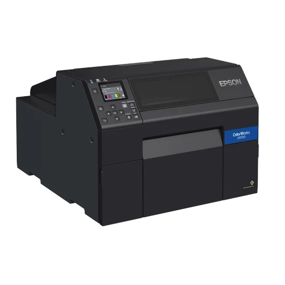
Page 1
Technical Reference Guide Product Overview Describes features for the product. Setup Describes setup and installation of the product. Handling Describes how to handle the product. Information for Application Development Describes how to control the printer and necessary information when you develop applications. Appendix Describes specifications of the product.
Page 2
• Neither is any liability assumed for damages resulting from the use of the information contained herein. • Neither Seiko Epson Corporation nor its affiliates shall be liable to the purchaser of this product or third par- ties for damages, losses, costs, or expenses incurred by purchaser or third parties as a result of: accident, mis- use, or abuse of this product or unauthorized modifications, repairs, or alterations to this product, or (excluding the U.S.) failure to strictly comply with Seiko Epson Corporation's operating and maintenance...
PC Provides videos that show you operating procedures and troubleshooting information. Access the videos from the following URL. <https://support.epson.net/p_doc/790/> The contents of videos are subject to change without notice. Downloading the Latest Version The latest versions of the printer driver, utilities, and manuals can be downloaded from the following URLs.
Symbols Used in This Guide The following symbols are used in this guide to indicate important information. Symbols for Safety The symbols shown below are used in this manual in order to ensure safety and proper use of this product and to prevent danger to you and other persons, and property damage.
Safety Precautions To ensure safe use of the product, be sure to read this manual and the other instruction manuals supplied with the product before use. Store this manual in a safe place so that you can resolve any unclear points regarding the product at any time.
Cautions on Handling • Do not use the product in a location with volatile substances such as alcohol or paint thinner present, or near fire. Doing so may cause electric shock or fire. • Shut down the product immediately if it produces smoke, a strange odor, or unusual noise. If you WARNING go on using the product, it may result in electric shock or fire.
Cautions on Power Supply • Do not allow dust or other foreign material to adhere to the power plug. Doing so may cause elec- tric shock or fire. • Do not use a power cord other than that supplied with the product. In addition, do not use the WARNING supplied power cord with another device.
Cautions on Ink Cartridges • The ink cartridges that can be used differ depending on the model number of the product. Use ink cartridges suitable for the model number of your printer. ("Ink Cartridges" on page 241) • Do not touch the IC chip on an ink cartridge. Doing so may result in normal operation and print- CAUTION ing becoming no longer possible.
• Store the ink cartridges in a place out of reach of children. • Epson recommends storing ink cartridges in a cool and dark place. • If you wish to use ink cartridges that have been stored in a cold place for a long period of time, leave them for at least 3 hours in a place that is at room temperature before use.
Caution Label The labels affixed to the product indicate the following cautions. Do not touch the roller at the bottom of the paper holder unit with your hand. Doing so may cause injury. WARNING Do not touch the manual cutter at the bottom of the peeler cover with your hand. Doing so may cause injury.
Restriction of Use When this product is used for applications requiring high reliability/safety such as transportation devices related to aviation, rail, marine, automotive etc.; disaster prevention devices; various safety devices etc.; or func- tional/precision devices etc., you should use this product only after giving consideration to including fail-safes and redundancies into your design to maintain safety and total system reliability.
Contents ■ Before Use..........................3 Manuals for This Product ..............................3 Symbols Used in This Guide............................4 Safety Precautions................................5 Cautions on Installation ..............................5 Cautions on Handling ...............................6 Cautions on Power Supply ..............................7 Cautions on Ink Cartridges..............................8 Cautions on the Maintenance Box ..........................9 Caution Label ..................................
Page 13
Printing Barcodes / 2D Symbols on .NET Environment ..................97 Favorite Settings................................99 User Defined Information ............................102 Exporting/Importing Printer Driver Settings ...................... 102 Starting PrinterSetting from the Printer Driver ....................105 Setting EPSON Status Monitor 3..........................106 Restrictions on Using the Printer Driver........................ 112...
Page 14
■ PrinterSetting ........................113 How to Start PrinterSetting ............................114 How to Apply Settings ..............................115 Media settings................................116 Layout settings................................117 Position adjustment ..............................119 Print results adjustment.............................. 121 Store data in the printer.............................. 122 Background image settings ............................123 Print head maintenance .............................
Page 15
Paper is jammed ................................197 Information for Application Development ..........204 ■ How to Control the Printer ....................204 Using the Epson Inkjet Label Printer SDK......................205 Using the ESC/Label Commands..........................205 Changing Printer Settings and Replacing Printer....................206 ■ Software and Manuals ...................... 212 Appendix......................
Page 16
■ Downloading Printer Driver, Utilities, and Manuals............ 249 ■ Label Print Applications....................249 How to Get Software..............................249 ■ For Inquiries ........................250...
Features: Equipped with an auto cutter. The paper can be cut either according to the application settings, or with the help of the Cut button on the operation panel. Model number: ColorWorks C6500Au, ColorWorks C6500Ae, ColorWorks C6510A, ColorWorks C6520A, ColorWorks C6530A, ColorWorks C6540A,...
Chapter1 Product Overview Part Names and Functions This section describes the main operation parts. Front Paper cover Peeler model Front cover Peeler cover Maintenance box cover Ink cartridge cover Name Description Front cover Open this cover to remove paper if it is jammed. "Paper is jammed"...
Chapter1 Product Overview Rear Air vent LAN port USB port Wire saddle Power connector Name Description Power connector Connect the power cable. Wire saddle Pass the USB cable through this saddle to pre- vent disconnection of the cable. USB port Connect a USB cable.
Chapter1 Product Overview Inside Label detector Edge guide Movable edge guide Release lever Paper guide unit Name Description Movable edge guide Supports paper at the paper width position while the paper is fed into the printer. Squeeze the blue lever to move the edge guide. Adjust them to match the paper width.
Chapter1 Product Overview Spindle and Flange Used to supply the paper from the inside. Flange Spindle Name Description Flange Attach this to the spindle to fix the roll paper loaded on the spindle. Squeeze the blue lever to attach or remove to/from the spindle. Spindle Load roll paper on this spindle.
Chapter1 Product Overview Operation Panel Screen (power) button Pause button Back Feed button Feed button Peeler model (home) button Peeler Reset button Auto cutter model (back) button Cut button (select) button, Cancel button OK button Name Description The status of the printer can be checked from the flashing of the LEDs. This allows you to know the cause of an error and how to resolve the problem.
Page 23
Chapter1 Product Overview Name Description Back Feed button Use to replace paper. Hold down this button to feed the paper backward until you can pull the paper out of the printer. Pause button If this button is pressed during printing, printing is stopped after printing of the cur- rent page is finished.
Chapter1 Product Overview Nozzle Verification Technology The “Nozzle Verification Technology” allows the printer to detect clogging of the print nozzles by self-check. Depending on required print quality, you can enable or disable the “Nozzle Verification Technology” function, set how often to run the self-check, threshold for the check, and whether to run a cleaning after the check. In addition to that, if nozzle clogging is not cleared by the cleaning, the printer carries out supplemental printing using nozzles adjacent to the clogged nozzles.
Page 25
Chapter1 Product Overview Setting Auto Nozzle Check Interval Specify the number of printouts to let the printer run the nozzle check when reached the number. The printer will stop while running the check. How to Set Set using the operation panel of the printer, or using PrinterSetting. Specify the number in the range of 1 to 13000.
Chapter1 Product Overview Dot Substitution (Supplemental Printing) Function The “Dot Substitution” function automatically supplements missing dots caused by clogged nozzles with dots generated by nozzles adjacent to the clogged nozzles. The number of nozzles that can be supplemented is up to 16 nozzles.
Chapter1 Product Overview Setting Periodic Auto Cleaning The printer is set to run an auto cleaning periodically to maintain the print head in good condition. You can change the time to start the cleaning. The cleaning takes 2 to 30 minutes. During the cleaning, printing is disabled. •...
Chapter1 Product Overview Checking the Printer Status Printing the Status Sheet By printing the status sheet, you can check the firmware version and the current printer settings, such as print mode and media detection settings. On the operation panel, select the menu in the order shown below to print the status sheet. [Menu] - [Printer Status/Print] - [Print Status Sheet] To print the status sheet, load paper that has a label that measures at least 4 inches width and 6 inches long.
Chapter1 Product Overview Printing the Network Connection Check Report By printing the network connection check report, you can check the network connection status and the network settings. On the operation panel, select the menu in the order shown below to print the report. [Menu] - [General Settings] - [Network Settings] - [Connection Check] To print the network connection check report, load paper that has a label that measures at least 4 inches width and 6 inches long.
Chapter1 Product Overview Checking the Status of Consumables On the home screen of the printer, you can check the following information; the status of the ink cartridges and the maintenance box, paper settings (paper type, detection method, label width/length), remaining amount of paper.
Chapter2 Setup Setup This chapter describes procedures for installing and setting up the printer that are required before using the printer. Unpacking After unpacking, make sure that all the printer and the accessories are included and they have no damages. The included items are as follows.
Chapter2 Setup Removing the Protective Materials Remove the all protective materials such as pieces of tape and cushion materials. There are eight protective materials and some of them have been attached to inside the printer.
Chapter2 Setup Installing the Printer Allow sufficient space for the printer. Make sure that the installation location meets the following requirements. • On a level and stable surface with sufficient strength to support the weight of the printer Auto cutter model: approx. 25.5 kg Peeler model: approx.
Chapter2 Setup Connecting the Power Cable Follow the procedure below to connect the power cable. ·Install the printer near a wall outlet so that you can disconnect the plug from the outlet immediately in the event of an emergency. WARNING Insert the power cable firmly all the way into the power connector on the back of the printer.
Chapter2 Setup Turning On/Off Turning the Power On Hold down the (power) button until the (power) LED lights up. Turning the Power Off Hold down the (power) button until a power-off confirmation message is displayed. Then select [Yes] on the confirmation screen.
Chapter2 Setup Installing the Ink Cartridges Follow the on-screen instructions to install the ink cartridges. When you set the ink cartridges and close the cover, initial ink charging will start. When the ink charging is fin- ished, the home screen is displayed. It takes about 18 minutes for the initial ink charging.
Chapter2 Setup Replacing the Ink Cartridges Checking Amount of Ink Remaining You can check ink level of each color ink cartridge on the home or an error message screen of the operation panel. Message Description You need to replace Ink Cartridge(s). To maintain the quality of the print head, the printer stops printing before ink car- tridges are completely expended.
Page 38
Chapter2 Setup Open the bag and take out the new ink cartridge. Shake the ink cartridge as shown in the figure below. Install the ink cartridge in the slot. Close the ink cartridge cover.
Chapter2 Setup Installing the Maintenance Box The printer comes with the maintenance box installed. Before handling the maintenance box, make sure to read the cautions on handling the maintenance box. "Cautions on the Maintenance Box" on page CAUTION Replacing the Maintenance Box Checking the Amount of Empty Space in the Maintenance Box You can check the remaining capacity of the maintenance box on the home or an error message screen of the operation panel.
Page 40
Chapter2 Setup Take out the maintenance box. When disposing of the used maintenance box, put it in a plastic bag that came with the new mainte- nance box. Take out a new maintenance box from the bag. Install the new maintenance box. Close the maintenance box cover.
Chapter2 Setup Installing the Printer Driver and Connecting to a Computer There are the following two methods to install the printer driver on a computer and connect the printer to the computer. • Setup using Install Navi • Setup without using Install Navi Setup using Install Navi Just by following the on-screen instructions of Install Navi, you can install the printer driver and connect the printer to the computer.
How to Get the Software You can get the software from the following website. For customers in North America, go to the following web site: www.epson.com/support/ For customers in other countries, go to the following web site: www.epson-biz.com/ How to Connect to a Computer Connect the interface cable to be used to the connector on the back of the printer.
Page 43
Chapter2 Setup Enter the IP address and the subnet mask. Select a setting to change and then press the [OK] button to enter the information. Select [Start Setup] and then press the [OK] button. The network setting is now complete.
Chapter2 Setup Media Settings Configure the media source to use, and type, shape, detecting method of media to use. • When using the Windows printer driver "Printer Driver" on page • When Not using the Windows printer driver "PrinterSetting" on page 113.
Videos that show the procedure are also available. Click the URL below to view the videos. <https://support.epson.net/p_doc/790/> Supply from Inside (Internal) Supply from Outside (Rear Feed) Paper is supplied from inside the printer.
Chapter2 Setup How to Load Paper (Auto Cutter Model - Supply from Inside) Turn on the printer, and then check that [Internal] is selected as the [Media Source] setting on the operation panel. ("Operation Panel Settings" on page 145) Open the paper cover. Remove the spindle from the printer.
Page 47
Chapter2 Setup Hold the spindle with both hands, and set it in the printer. Install the spindle so that both ends of the spindle fit into the holders inside the printer. Slide the movable edge guide to the right side. Squeeze the blue lever to move the edge guide.
Page 48
Chapter2 Setup Place your hand on the paper to flatten it, and slide the movable edge guide against the paper. If the movable edge guide is not properly slided against the paper, print position may become incorrect or a paper jam may occur. Make sure to follow the guidelines below. CAUTION •...
Page 49
Chapter2 Setup Close the paper cover. Press the [Pause] button. Loading paper (auto cutter model - supply from inside) is now completed.
Chapter2 Setup How to Load Paper (Auto Cutter Model - Supply from Outside) Turn on the printer, and then check that [Rear Feed] is selected as the [Media Source] setting on the operation panel. ("Operation Panel Settings" on page 145) Open the paper cover.
Page 51
Chapter2 Setup Place the fanfold paper behind the printer. • Place the fanfold paper at least 100 mm away from the printer. • Make sure the paper is vertical in relation to the paper feed slot. 100 mm or more Make sure not to let the fanfold paper to curl near the printer.
Page 52
Chapter2 Setup Pull the paper along the right edge guide. Place your hand on the paper to flatten it, and slide the movable edge guide against the paper. If the movable edge guide is not properly slided against the paper, print position may become incorrect or a paper jam may occur.
Page 53
Chapter2 Setup Insert the paper into the paper feed slot until paper feeding starts automatically. Do not load backing paper that has no labels on it. The paper may not be detected and not be fed automatically. Close the paper cover. Press the [Pause] button.
Chapter2 Setup How to Load Paper (Peeler Model - Supply from Inside) Turn on the printer, and then check that [Internal] is selected as the [Media Source] setting on the operation panel. ("Operation Panel Settings" on page 145) Open the paper cover Remove the spindle from the printer.
Page 55
Chapter2 Setup Hold the spindle with both hands, and set it in the printer. Install the spindle so that both ends of the spindle fit into the holders inside the printer. Slide the movable edge guide to the right side. Squeeze the blue lever to move the edge guide.
Page 56
Chapter2 Setup Place your hand on the paper to flatten it, and slide the movable edge guide against the paper. If the movable edge guide is not properly slided against the paper, print position may become incorrect or a paper jam may occur. Make sure to follow the guidelines below. CAUTION •...
Page 57
Chapter2 Setup Close the paper cover. Hold down the [Feed] button until the leading edge of paper touches the table on which the printer is installed. Remove labels from the ejected paper. Open the peeler cover. Do not touch the manual cutter at the bottom of the peeler cover with your hand. Doing so may cause injury.
Page 58
Chapter2 Setup Pass the paper through the peeler slot. Peeler slot Close the peeler cover. If the paper is loose, pull the leading edge of paper to remove the looseness and then close the peeler cover. Press the [Pause] button. Loading paper (peeler model - supply from inside) is now completed.
Chapter2 Setup How to Remove Paper (For the Auto Cutter Model) Check that the printer has been turned on. Press the [Cut] button, and cut off the ejected labels. Press the [Back Feed] button to feed the paper backward. The paper can now be pulled out from inside the printer. Open the paper cover.
Chapter2 Setup How to Remove Paper (For the Peeler Model) Check that the printer has been turned on. Open the peeler cover. Cut the backing paper near the paper ejection slot. Press the [Back Feed] button to feed the paper backward. The paper can now be pulled out from inside the printer.
Page 61
Chapter2 Setup Slide the movable edge guide away from the paper, and remove the paper. Removing the paper is now completed. To load paper, see the following pages. "How to Load Paper (Peeler Model - Supply from Inside)" on page 54...
Chapter2 Setup How to Eject Paper at Paper End (For the Auto Cutter Model) Hold down the Feed button until the paper is completely ejected. Ejecting paper at paper end is now completed. To load paper, see the following pages. "How to Load Paper (Auto Cutter Model - Supply from Inside)"...
Chapter2 Setup How to Eject Paper at Paper End (For the Peeler Model) Open the peeler cover. Remove the paper from the peeler slot. Peeler slot Hold down the Feed button until the paper is completely ejected. Ejecting paper at paper end is now completed. To load paper, see the following pages.
Chapter2 Setup Test Print You can check whether the printer operates normally or not by printing a nozzle check patterns. Follow the procedure below to print the nozzle check patterns. The nozzle check patterns allow you to check print nozzles for clogging. Turn the printer on.
Chapter2 Setup Test Print using the Printer Driver If you have already installed the printer driver, you can do a test print using the printer driver. Follow the procedure below to do the test print. Open [Devices and Printers]. Right-click the icon of the printer, and then click [Printer properties]. The Printer properties screen appears.
Chapter3 Handling Handling This chapter provides basic information necessary for handling the printer. Printer Driver This chapter describes how to operate the printer driver. The printer driver is software to control the printer in accordance with the print instructions of application soft- ware.
Chapter3 Handling Printer Driver Screen Configuration The printer driver is equipped with a help function. Right-click an item and then click Help to display an expla- nation on the item. Current Settings pane Displays a summary of current settings. General tab Lets you set media (paper) size, media form, and other basic print settings.
Chapter3 Handling Paper Source and Paper Detection Settings Open the printer driver window. Click [Media Detection...] on the General tab.
Page 69
Chapter3 Handling Make the following settings to match them with the paper you use. • Media Source: Select how to supply paper to the printer. Setting item Description Internal roll (supply from Inside) Paper is supplied from inside the printer. Set roll paper attached to the spindle into the printer.
Chapter3 Handling Click [OK]. Paper source and paper detection settings are now complete. User-Defined Paper The size, form, type, and other settings of frequently used paper can be registered to the printer driver as a media definition. This is convenient because you will not need to set the paper settings of the driver when print- ing from an application if you register a media definition in advance.
Page 71
Chapter3 Handling Click the [New] button. The New screen appears. Make the following settings to match them with the paper you use. Media Name Enter the name of the media definition. This is the name displayed when you select a paper size from an application.
Page 72
Chapter3 Handling Label width Enter the width of the label. • Continuous label: label width excluding the backing paper • Die-cut label: Label width excluding backing paper Label length Enter the length of the label. • Continuous label: Length of the print range (length of one page) •...
Page 73
Chapter3 Handling Media Saving (for continuous label only) Select a media saving setting. The [Media Saving] function eliminates margins from one-page print data to suppress wasting paper. When the [Media Saving] function is enabled, printing a barcode using the barcode font of the printer driver is disabled.
Page 74
Chapter3 Handling Print Quality Select the print quality. When [Media Type] is [Matte Paper] or [Synthetic] • High Speed: 300 x 600 dpi • Speed: 600 x 600 dpi • Standard: 600 x 600 dpi (initial setting) • Quality: 600 x 1200 dpi When [Media Type] is [Glossy Paper], [Glossy Film], or [High Glossy Paper] •...
Page 75
Chapter3 Handling Click [OK]. Check that the registered media name is displayed in the Media Definition screen and then click [Close]. Check that you can select the registered media name in [Media Name] on the [Gen- eral] tab.
Page 76
Chapter3 Handling Click the [OK] button to close the driver. Paper registration (media definition) is now complete.
Page 77
Chapter3 Handling Editing and Deleting Open the printer driver window. Click the [Media Definition] button on the [General] tab. The Media Definition screen appears. Click to select the media definition you wish to edit or delete.
Page 78
Chapter3 Handling If you wish to change the definition settings, click the [Edit] button. The Edit screen appears and you can change the definition. If you wish to delete the definition, click the [Delete] button. A screen appears and if you click the [OK] button, the definition is deleted.
Chapter3 Handling Printing Barcodes The printer has built-in fonts. This allows you to print a barcode without creating it on an application software. Barcode Font Settings You can make the barcode settings using [Barcode and 2D Symbol Settings] on the [Driver Utilities] tab. Make the following settings.
Page 80
Chapter3 Handling • Rotation Settings: Select an option to rotate a barcode. • Hexadecimal Input Mode: Select the check box to enter data for a barcode in hexadecimal. • Module: Specify the width of the narrowest element of the barcode in units of dot. •...
Page 81
Chapter3 Handling Recommended Module Values Print directions of a barcode are as shown below. The recommended module values vary by paper type, barcode type, and the print direction. Paper width direction Paper width direction Fence barcode Ladder barcode • You cannot change the orientation of a QR code, Micro QR code, and Maxi code by setting [Orien- tation] on the [Options] tab to [Landscape].
Page 82
Chapter3 Handling ANSI Grade C or higher minimum module size [in units of 300 dpi] Orienta- Barcode High tion Matte Syn- Glossy Glossy Glossy Paper thetic Paper Film Paper Fence Ladder GS1 DataBar Omnidirectional Fence Ladder GS1 DataBar Truncated Fence Ladder GS1 DataBar Limited Fence...
Page 83
Chapter3 Handling ANSI Grade C or higher minimum module size [in units of 600 dpi] Orienta- Barcode High tion Matte Syn- Glossy Glossy Glossy Paper thetic Paper Film Paper Code128 Fence Ladder GS1-128 Fence Ladder Fence Ladder GS1 DataBar Omnidirectional Fence Ladder GS1 DataBar Truncated...
Page 84
Chapter3 Handling How to Specify Barcode Data See the following descriptions to specify barcode data. About the composite symbol: Switching between CC-A and CC-B is automatically performed, however, to use CC-C, you need to specify to use it. (For GS1-128, the type of composite component can be selected from [No composite], [CC-A/CC-B], and [CC- C].) Composite component type Encodable number of digits...
Page 85
Chapter3 Handling Code93 • A start code, two check digits, and a stop code will be automatically added. • A character () that indicates a start code is printed at the beginning of the HRI characters. • A character () that indicates a stop code is printed at the end of the HRI characters. •...
Page 86
Chapter3 Handling Code128 • If you have disabled the auto convert function, enter a two-digits start code at the beginning of the data. If you have enabled the auto convert function, the type of start character is automatically determined and you do not need to specify the type in your application.
Page 87
Chapter3 Handling GS1-128 • ‘()’ are used as delimiters for the application identifiers. (printed as the HRI character, but not encoded.) • A start code (CODE A, CODE B, CODE C) and a stop code will be automatically added. • A symbol character FNC1 is automatically added next to the start code. •...
Page 88
Chapter3 Handling GS1 DataBar Expanded • ‘()’ are used as delimiters for the application identifiers. (printed as the HRI character, but not encoded.) • Be sure to include all the application identifiers in the data. • If the first data is “01” when an application identifier, left and right parentheses, and * are excluded, the 14th digit counted from the digit next to “01”...
Page 89
Chapter3 Handling How to Print Open print data file in an application, and specify barcode font, point, and language that you have set on the printer driver, and then print it. • The barcode size cannot be changed from the point set in [Specified Point]. If you specify a size other than the specified one, the barcode is not printed.
Chapter3 Handling Printing 2D Symbols The printer driver has the built-in 2D symbol font. This allows you to print a 2D symbol without creating it on an application software. Setting the 2D Symbol Font You can make the 2D symbol settings using [Barcode and 2D Symbol Settings] on the [Driver Utilities] tab. Make the following settings.
Page 91
Chapter3 Handling Make the settings for the barcode type you selected. • Settings for PDF417 ∗ Module Width: Set module width of PDF417. For the recommended value, see "Recommended Module Values" on page 93. ∗ Module Height: Specify the ratio of PDF417 module height to the module width. For the recommended value, see "Recommended Module Values"...
Page 92
Chapter3 Handling • Settings for AztecCode ∗ Type: Select a type of AztecCode. ∗ Cell Size: Select a size of a cell (module) of AztecCode. For the recommended value, see "Recommended Module Values" on page 93. ∗ Number of Layers: Specify the number of layers of AztecCode.
Page 93
Chapter3 Handling Recommended Module Values The recommended module values vary by paper type, 2D symbol type, and the print direction. 2D Symbols - Stacked code type ❏ 300 dpi ANSI Grade C or higher minimum module size [in units of 300 dpi] Orienta- 2D Symbols High...
Page 94
Chapter3 Handling 2D Symbols - Matrix code type ❏ 300 dpi ANSI Grade C or higher minimum module size [in units of 300 dpi] Orienta- 2D Symbols High tion Matte Syn- Glossy Glossy Glossy Paper thetic Paper Film Paper QR Code Micro QR Aztec DataMatrix...
Page 95
Chapter3 Handling Specifying Data of 2D Symbols See the following descriptions to specify 2D symbol data. PDF417 / MicroPDF417 • If the number of columns and rows is 0, they are automatically calculated. • When specifying a number other than 0, specify the numbers so that multiplying the columns by the rows equals 928 or lower.
Page 96
Chapter3 Handling GS1 DataBar Expanded Stacked • Multiple GS1 DataBar Expanded barcodes can be stacked. The way to specify the data is the same with that for GS1 DataBar Expanded. For details, see "GS1 DataBar Expanded" on page 88. • Printing the 2D symbol with a composite symbol is supported. When printing the 2D symbol with a compos- ite symbol, use “\|”...
Chapter3 Handling Printing Barcodes / 2D Symbols on .NET Environment Since .NET Framework supports only True Type fonts and Open Type fonts, barcode or 2D symbol fonts regis- tered in the printer driver cannot be printed. To solve the problem, use the [Font Replacement] function of the printer driver to replace a True Type font with the barcode or 2D symbol font.
Page 98
Chapter3 Handling Printing Barcodes/2D Symbols In the print data file, specify the True Type font that you replaced with the barcode or 2D symbol font, and spec- ify the point and language. • The point of barcode or 2D symbol is predetermined. Check the point in the [Barcode and 2D Symbol Settings] on the [Driver Utilities] window.
Chapter3 Handling Favorite Settings The Favorite Settings function allows you to register and manage print settings of the printer driver. Note that this function is completely different from the [Favorite Setting] available from the control panel of the printer, and they are not compatible with each other. The print settings include the settings available on the [General] and [Options] windows.
Page 100
Chapter3 Handling Features • When printing from an application, the registered print settings can be set as default print settings. After you make print settings, click [Save as Favorite Setting] to register the print settings. • Many sets of print settings can be registered in [Favorite Settings]. If you frequently use multiple sets of print settings due to use of different sizes or types of paper or other rea- sons, register each set of the print settings to [Favorite Settings] so that you can complete print settings just by selecting the set from the [Favorite Settings] list.
Page 101
Chapter3 Handling Enter a name of the settings in the [Name] field, and then click [Add]. The Save/Delete Favorite Setting screen is closed. Current Settings pane Check that the name of the added print settings is displayed in the list of [Favorite Settings].
Chapter3 Handling User Defined Information The following information is included in User Defined Information. • User-defined paper settings • Registered barcode font settings • Font replacement settings for .NET environment The user defined information is set on each client computer. If multiple printer drivers have been installed on one computer, the information can be shared between the multiple printer drivers.
Page 103
Chapter3 Handling Select the [Driver Utilities] tab. Click [Import/Export Settings]. Export in a BSF file from the current settings. If you export it from the general setting, a different content will be exported. • Current Settings: Properties of the printer driver - [General] - [Printing References] - [Driver Utilities] - [Import/ Export Settings] •...
Page 104
Chapter3 Handling Importing Settings File When the BSF file is imported to the printer driver, the printer driver settings are overwritten with the imported settings. If you keep the following settings unchanged, create BSF files to include them. • List of Favorite Settings •...
Chapter3 Handling Starting PrinterSetting from the Printer Driver Start PrinterSetting from the printer driver following the steps below. Open the printer driver window. Select the [Printer Utilities] tab. Click [Printer Settings]. The CW-C6XXX PrinterSetting screen appears.
Chapter3 Handling Setting EPSON Status Monitor 3 EPSON Status Monitor 3 displays a pop-up window to inform you specified paper type and ink levels when you start printing. In addition, if a fatal error occurs, it displays an error window.
Page 107
Chapter3 Handling In the [EPSON Status Monitor 3 Settings] field on the [Driver Utilities] window, [EPSON Status Monitor 3] and [Monitoring Preferences] are displayed.
Page 108
• When an error occurs during printing, the error information is displayed. IF an error occurs on the printer while it is not printing, EPSON Status Monitor 3 does not start. • You can start EPSON Status Monitor 3 anytime by clicking its icon on the task bar.
Page 109
Chapter3 Handling • You can set the following in the [Monitoring Preferences] settings. Display the EPSON Status Monitor 3 icon on the task bar. (See "Displaying the Icon" on page 111.)
Page 110
Chapter3 Handling Error Notification Settings Follow the procedure below to change the error notification settings of EPSON Status Monitor 3. Turn the printer on. Open the printer driver window. Select the [Driver Utilities] tab and then click [Monitoring Preferences]. If you have not enabled EPSON Status Monitor 3, [Monitoring Preferences] is not displayed. Enable EPSON Status Monitor 3 referring to "Enabling/Disabling EPSON Status Monitor 3"...
Page 111
Chapter3 Handling Displaying the Icon You can set to show the icon on the task bar, and check the printer status by clicking the icon. The icon is not displayed by default. Follow the procedure below to display the icon. Turn the printer on.
[Print spooled document first] enabled, the print jobs may not be printed in time order. • When using Epson printer driver, do not change the control prefix, the format prefix, and the delimiter string that are included in ESC/Label command from their defaults. If you change them, printing will not be per- formed or result in producing unintended printouts.
Chapter3 Handling PrinterSetting If you start PrinterSetting with user privileges, you may not be able to change the settings while the printer driver or other software is communicating with the printer. PrinterSetting is a utility that allows you to configure the printer settings. The following shows a summary of available settings with PrinterSetting.
Start PrinterSetting by following the steps below. Turn the printer on. Click [Start] - [EPSON] - [CW-C6XXX PrinterSetting]. The Select printer window appears. Select a search target, and then click [Search]. The printer is displayed in the list. Select the printer, and then click [OK].
Chapter3 Handling PrinterSetting is started. How to Apply Settings After you change the printer settings, click [Apply settings] to apply the changes to the printer.
Chapter3 Handling Media settings Allows you to make settings of paper to be used on the printer. This is not displayed if you start PrinterSetting from the printer driver. Item Description Media detection Media source Allows you to change the paper feed setting. settings Media detection Allows you to set paper detection setting.
Chapter3 Handling Layout settings Allows you to change the paper layout settings and create a user-defined layout settings. This is not displayed if you start PrinterSetting from the printer driver. Item Description Layout settings Media layout Allows you to make paper layout settings. Edit layout…...
Page 118
Chapter3 Handling Layout settings Item Description Media layout name Allows you to set a name for a new paper layout settings. Enter a name to set. Defined media layout If one or more sets of user-defined paper layout settings already exist, they are listed here.
Chapter3 Handling Position adjustment Allows you to adjust print start position and cut position. Item Description Positioning Print start position adjustment Allows you to adjust the print start position in the vertical (Vertical direction) direction. Adjustment procedure "Start adjustment" on page 120 Print start position adjustment Allows you to adjust the print start position in the horizontal (Horizontal direction)
Page 120
Chapter3 Handling Start adjustment The window shown below appears when you click [Start adjustment]. (The window is of Print start position adjustment (Vertical direction).) Enter a value in the [Adjustment value] box, and then click [Apply settings]. A confirmation window appears. If you click [Yes], the change is applied. The result is displayed.
Chapter3 Handling Print results adjustment Allows you to adjust colors and barcode. This is not displayed if you start PrinterSetting from the printer driver. Item Description Color preset Mode Allows you to change the correction method. Ink profile Allows you to adjust print density. To ensure print quality, adjust this when you change paper.
Chapter3 Handling Store data in the printer Allows you to register images, templates, fonts, character code tables, and spot colors to the printer. Item Description Image (Only .png) You can register images to be used for preprinting or templates. Template Allows you to register templates.
Chapter3 Handling Background image settings Allows you to configure a background image. • Use this function when using the following software. ∗ Windows driver from Zebra Technologies Corporation ∗ A commercially available label printing application that supports this printer ∗ An application that directly controls ZPL II or ESC/Label commands •...
Page 124
• Windows driver from Zebra Technologies Corporation • A commercially available label printing application that supports this printer • An application that directly controls ZPL II or ESC/Label commands The Epson printer driver does not support printing a background image.
Chapter3 Handling Print head maintenance Allows you to run a print head cleaning or nozzle check, and make settings for periodic cleaning. Item Description Print head mainte- Print head cleaning Runs a nozzle check and clears nozzle clogging. Click [Start] to run the clean- nance ing.
Chapter3 Handling Printer settings Allows you to configure the printer settings. Item Description Preferences Power on action Select a printer action when the printer is powered on. Paper replacement Select a printer action when paper is replaced. action Back Feed Sequence Select the back feed timing.
Chapter3 Handling Print Head Alignment Allows you to adjust the print head. Item Description Media Feed Adjustment Carry out this adjustment when white or black banding/streaks appear on printouts. Adjustment procedure "Media Feed Adjustment" on page 128 Bi-directional Printing Adjustment Carry out this adjustment when printed lines are skewed or misaligned, or printed text looks blurred.
Page 128
Chapter3 Handling Media Feed Adjustment This allows you to adjust paper feeding when white or black banding/streaks appear on printouts. Adjustment method Description Do not print adjustment sheet Select this method if you do not have die-cut label, continuous paper, or full-page label paper with a length of 66.7 mm or longer.
Page 129
Chapter3 Handling An adjustment start confirmation window appears. Click [Yes]. The second Media Feed Adjustment window appears. In the same way as step 4, look at the print results and then select a setting value. When adjustment is complete, a complete window appears. Click [OK]. Print the data prepared in step 1 again.
Page 130
Chapter3 Handling In the same way as step 4, look at the print results and then select a setting value. An adjustment start confirmation window appears. Click [Yes]. When adjustment is complete, a complete window appears. Click [OK]. Bi-directional Printing Adjustment When printed vertical or horizontal lines look skewed or misaligned, or when printed text looks blurred, per- form the Bi-directional Printing Adjustment.
Page 131
Chapter3 Handling Check the sheet and then select the number for the pattern with the least gaps or overlapping in each of #1, #2, and #3 groups, and then click [OK]. Adjustment sheet print example (for this sheet, select “2” for #1 group, select “0” for #2 group, and select “2”...
Chapter3 Handling Panel settings Allows you to configure the panel settings. Item Description Panel button settings Cancel button Select whether to enable or disable the cancel button. Feed button Select whether to enable or disable the feed button. Cut button (Auto cutter Select whether to enable or disable the cut button.
Chapter3 Handling Operating Time Settings Allows you to change the power saving settings. Item Description Power Saving Transition Time Settings Set a time period to let the printer enter into the power saving mode after completion of printing.
Chapter3 Handling Nozzle check settings Allows you to change the nozzle check settings. Item Description Nozzle check Trigger to Head Specify the maximum number of clogged nozzles that is allowed to con- settings Maintenance tinue printing. Additional auto Select whether to run an auto nozzle check during printing. nozzle check during printing Nozzle check...
Chapter3 Handling Advanced settings Allows you to configure the advanced printer settings. Item Description Calibration Allows you to carry out calibration of sensors. Replace settings Replace settings Allows you to make and apply settings for replacing from printer using from printer using from printer using ZPL II commands.
Page 136
Chapter3 Handling Replace settings from printer using ZPL II commands If you click [Default settings], the default settings of the printer are applied on the window. Then click [Apply settings] to apply the default settings. Click [Set...] for [Replace settings from printer using ZPL II commands] to open the setting window.
Page 138
Chapter3 Handling The “Register Printer’s Favorite Settings” window appears. Enter a name for the set- tings in the [Favorite Settings Name] box, and make the settings in [Printer’s Favorite Settings]. When finished, click [Set]. • For the favorite settings name, you can use up to 15 ASCII (20h to 7Eh) characters excluding ^, ~, :, comma, and period.
Page 139
Chapter3 Handling Applying Favorite Settings Follow the procedure below to apply the registered favorite settings to the printer. Click [Select the Favorite Settings] in [Set Printer’s Favorite Settings]. The “Select Printer’s Favorite Settings” window appears. In the [Favorite Settings Name] box, select a set of favorite settings you want to apply to the printer, and then click [Apply settings].
Chapter3 Handling Initialize printer Allows you to initialize the printer. When the printer is initialized using the [Initialize] menu, all image files and setting files you have registered are deleted. CAUTION Item Description Initialize Factory reset Returns the printer settings to their defaults. Erase memory Initializes the extended memory.
Chapter3 Handling Printer information Displays information of the printer. Item Description Printer information Printer settings list Click [View...] to see the current settings of the printer. See "Printer set- tings list" on page 142. Maintenance counters Allows you to check the maintenance counters.
Page 142
Chapter3 Handling Printer settings list The “Printer settings list” window appears when you click [View...]. You can save the settings as a file by clicking [Output to file...].
Chapter3 Handling Settings save and restore Allows you to save the settings of the printer and restore the saved settings. Item Description Save settings Save data Select setting items to save. Select the check box for the items. Save to folder Specify a folder to save the file.
Chapter3 Handling Option A unit of length used in PrinterSetting and start up setting can be changed. Item Description Display settings Units Select a unit of length. Startup Settings Display a welcome Select whether to display welcome screen at startup. screen at startup The [Units] setting is for PrinterSetting itself.
Chapter3 Handling Operation Panel Settings Setting menu Settings Default • Matte Paper Paper Set- Media Type Matte Paper tings • Synthetic • Glossy Paper • Glossy Film • High Glossy Paper • Gap Media Detect • Black Mark • None •...
Page 146
Chapter3 Handling Setting menu Settings Default Mainte- Print Head Nozzle Check nance Print Head Cleaning Power Cleaning Ink Cartridge Replacement Maintenance Box Replacement • Vertical Alignment Print Head Alignment • Horizontal Alignment • Simple Media Detect Calibration • Media Detect •...
Page 147
Chapter3 Handling Setting menu Settings Default General Basic Date/ Date/Time Settings Settings Time Time Difference +13:45 to -12:45 Settings (in increments of 15 min.) • Nederlands Language English • English • Français • Deutsch • Ελληνικά • Italiano • 日本語 •...
Page 148
Chapter3 Handling Setting menu Settings Default • High Speed General Printer Print Print Quality Normal • Speed Settings Settings Settings • Normal • Quality • Max Quality • 200dpi Resolution 600dpi • 300dpi • 600dpi Com- Control Prefix 0X20 to 7E 0X7E mand Format Command...
Page 149
Chapter3 Handling Setting menu Settings Default General Printer Print Print Mode For auto cutter model: For auto cut- • Cut ter model: Settings Settings Options • Stop at Cut • Stop at Cut Position Position • Stop at Peel-Off Posi- For peeler tion model:...
Page 150
Chapter3 Handling Setting menu Settings Default • Feed General Printer Print Actions when Replacing Media Feed • Not Feed Settings Settings Options • Calibration • Short Calibration • Check Media Size • Feed Actions on Power On Not Feed • Not Feed •...
Page 151
Chapter3 Handling Setting menu Settings Default General System Clear Internal Memory Data Settings Adminis- Security Admin Admin Register tration Settings Settings Password Change Reset • Off Lock Setting • On Restore Network Settings Default Media Detect Settings Roll Media Tension All Settings Language Favorite Settings...
Chapter3 Handling WebConfig WebConfig is an application software that allows you to check or change the printer settings using a web browser on a computer. To use WebConfig, you need to set up an IP address to the printer in advance. Connect the computer to the same network as the printer.
Page 153
Chapter3 Handling How to Start WebConfig Start a web browser on a computer or device that is connected via a network, and then type the printer IP address into the browser. Enable the JavaScript on the browser. Because the communication with the printer uses a self-signed certificate of the printer over HTTPS, a warning message is displayed on the browser when you start WebConfig.
Chapter3 Handling Spot Color Settings [Spot Color Settings] allows you to change a specified color to another specified color. First create the color con- version setting file, then when printing, specify the setting file to print with the color conversion applied. Follow the procedure below to create the color conversion setting file.
Page 155
Chapter3 Handling Determine RGB settings of a target color. To determine the target color, it is recommended to use “Color Tone Matching Assistant” bundled in the included software disc. Color Tone Matching Assistant lets you enter the RGB settings of the original color, creates some sample colors by slightly changing the original RGB settings, and then lets you print the samples.
Page 156
Chapter3 Handling Select [Store data in the printer]. Click [Create] button in the [Spot color table] field. Enter the original RGB settings and the target RGB settings.
Page 157
Chapter3 Handling Click [Add]. The specified pair of RGB settings will be added in the box. Click [Confirmation]. A window to enter a name for the spot color setting is displayed. Enter a name for the setting file, then click [OK].
Page 158
Chapter3 Handling When you select [OK] on a successfully saved dialog box, the [Created spot color list] window appears. If you want to copy the file to another location, click [Copy to another folder]. Creating spot color setting file is now complete.
Chapter3 Handling Printing using the Spot Color Setting File Open the printer driver window. Select [Spot Color Settings] on the [General] window. From the pull-down menu, select a spot color setting file you want to use. To change the folder to view, click [Update Spot Color List] and change the folder. Print the file.
Chapter3 Handling Color Correction There are the following three methods for color correction. • Setting on the printer • Setting using ICM of Windows OS • Setting using an application software According to which method you use, set [Color Correction Mode] of the printer driver as follows. •...
Page 161
Chapter3 Handling Item Description Brightness Lets you adjust brightness of the entire image. Contrast Adjust the contrast of the entire image. When the contrast is increased, bright portions become more bright, and dark portions become more dark. When the contrast is decreased, difference between light and dark is reduced.
Chapter3 Handling ICM (Image Color Management) is a Windows color control function to match apparent color between differ- ent devices such as a monitor and a printer. Apparent color on the monitor and on the printout is matched based on ICC profiles. An ICC profile is a file that describes characteristics of the device such as a monitor and a printer according to ICC (International Color Consortium) standards.
Printer Profile Select a printer profile to use for color correction. Normally, only [EPSON Standard] is displayed. [EPSON Standard] automatically selects an ICC profile that is appropriate for the [Media Type] and [Print Quality] settings on the printer driver.
Chapter3 Handling Opening the Paper Cover This section describes how to open the paper cover. Do not use the printer with the paper cover removed. Doing so will cause the printer to malfunction. CAUTION Opening the Cover using the Lever in the Front Open the paper cover as shown above for the following purposes.
Chapter3 Handling Printing from the First Label (Auto cutter model only) If the [Media Detect] setting has been set to [Gap], you cannot print on the first label (printed from the second label) at the first time printing after loading paper. However, for the auto cutter model, even when [Gap] is selected as [Media Detect], you can prevent missing of the first label by following the procedure below.
Chapter3 Handling Adjusting Label Detector When printing on odd-shaped labels such as circle or oval, set the label gap detectors as described below. This adjustment is not required when using labels that are general in shape, such as square labels and full-page labels.
Chapter3 Handling Adjusting Label Detector for Circle Die-cut Labels (Example) Align the center of the circle die-cut label, which is shown by dotted line in the figure, with the adjustment tabs. Center of Circle Gap between Labels Position of the detector...
Chapter3 Handling Cleaning the Printer This chapter describes how to carry out maintenance of the printer. Front Peeler model Cleaning the Auto Cutter (Auto Cutter Model Only)( Page 170) Cleaning the Peeler (Peeler Model Only)( Page 172) Cleaning the Platen( Page 174) Cleaning the Paper Pressure Roller...
Chapter3 Handling Cleaning the Exterior Turn off the printer, and then wipe off any dirt with a dry cloth or non-woven fabric that has been dampened. Make sure to unplug the printer when cleaning it. Do not use alcohol, benzine, thinner, trichloroethylene, or ketone based solvent to clean the exterior of the printer.
Chapter3 Handling Cleaning the Auto Cutter (Auto Cutter Model Only) If labels, paper dust, or adhesive has adhered to the fixed blade of the auto cutter, the blade may become dull. Clean the fixed blade following the procedure below. Fixed blade If paper has been loaded, remove it.
Page 171
Chapter3 Handling Turn off the printer, and unplug the power cable. As shown in the figure below, scrape off adhered materials stuck to the fixed blade using a flat-blade screwdriver (blade width: 1.8 mm to 3 mm). Start scraping from each end toward the center.
Chapter3 Handling Cleaning the Peeler (Peeler Model Only) If labels, paper dust, or adhesive has adhered to the peeler, the print quality may decline. To maintain good print quality, it is recommended to clean the peeler every day. Clean the peeler following the procedure below. Make sure the printer has been turned off.
Chapter3 Handling Cleaning the Edge Guides If labels, paper dust, or adhesive has adhered to the edge guides, paper may get jammed, or printing position may become incorrect. Clean the edge guides following the procedure below. Make sure the printer has been turned off. Open the paper cover.
Chapter3 Handling Cleaning the Platen If labels, paper dust, or adhesive has adhered to the platen, paper may get jammed, or printing position may become incorrect. Clean the platen following the procedure below. Make sure the printer has been turned off. If paper has been loaded, remove it.
Chapter3 Handling Cleaning the Paper Feed Roller If paper dust or adhesive has adhered to the paper feed roller, paper may get jammed, or faint or blurred image may be printed. Clean the roller following the procedure below. When cleaning the paper feed roller, do not use a material other than labels. Doing so may damage the roller resulting in paper jam, or faint or blurred printout.
Page 176
Chapter3 Handling Raise the release lever. Open the paper guide unit. Attach adhesive side of a label to the roller, and peel it off slowly. Repeat this action until paper dust or adhesive is completely removed from side to side of the roller. If some labels have stuck on the roller, carefully remove them as they can cause a paper jam.
Page 177
Chapter3 Handling Rotating the roller by hand, remove paper dust or adhesive from entire surface of the roller.
Chapter3 Handling Cleaning the Paper Pressure Roller If paper dust or adhesive has adhered to the paper pressure roller, paper may get jammed, or faint or blurred image may be printed. Clean the roller following the procedure below. When cleaning the paper pressure roller, do not use a material other than labels. Doing so may damage the roller resulting in paper jam, or faint or blurred printout.
Page 179
Chapter3 Handling Raise the release lever. Open the front cover. Attach adhesive side of a label to the roller, and peel it off slowly. Repeat this action until paper dust or adhesive is completely removed from side to side of the roller. If some labels have stuck on the roller, carefully remove them as they can cause a paper jam.
Chapter3 Handling Print Head Cleaning If the nozzles are clogged, faint colors, banding, or unintended colors appear on printouts. When such print quality problems occur, print nozzle check patterns and check for nozzle clogging. ("Test Print" on page Normal Clogging If nozzles are clogged, run a print head cleaning.
Chapter3 Handling Using the Operation Panel [Menu] - [Maintenance] - [Print Head Cleaning] [Menu] - [Maintenance] - [Power Cleaning] Using the Printer Driver Click [Print Head Cleaning] or [Power Cleaning] on the [Printer Utilities] window. Using the WebConfig Select [Print Head Cleaning] on the [Maintenance] window. Then select the cleaning type from [Auto] or [Power Cleaning], and then click [Start].
Chapter3 Handling Storing the Printer for Long Periods with Ink Cartridges Installed Before Storing the Printer If you need to store the printer for long periods after installing the ink cartridges, follow the procedure below. Run the nozzle check to confirm that the print head nozzles are not clogging and there is no problem with the print quality.
Chapter3 Handling For Using the Printer after Long Storage When using the printer after storing it for long periods, follow the procedure below. Check the ink cartridges to see if they are expired. Replace the ink cartridges with new ones in the following cases. For instructions on how to replace the cartridges, see "Installing the Ink Cartridges"...
Chapter3 Handling For Transporting the Printer When transporting the printer, make sure to follow the guidelines below. • The weight of the printer is approximately 26 kg. When lifting the printer, make sure to lift it by two people placing the hands at the dents on the printer. If you put your hands on the other portions of the printer to lift it, the printer may get damaged.
Chapter3 Handling Troubleshooting A message is displayed on the operation panel. Message Meaning Solution Information The paper cover is open. Close the paper cover. Close the paper cover. ("Part Names and Functions" on page Information The front cover is open. Close the front cover.
Page 186
Chapter3 Handling Message Meaning Solution Information The fanfold paper is not Load fanfold paper. loaded. The fanfold paper is not ("Loading Paper" on page loaded. Information A paper jam has occurred. Remove the jammed paper and then load paper. Paper jam. ("Paper is jammed"...
Page 187
Epson products. Repairs for any damage or breakdown of this product due to the use of non-gen- uine Epson products will not be free of charge even if the warranty period is still valid. Information...
Page 188
Chapter3 Handling Message Meaning Solution Maintenance Request: End Of The printer internal parts have Printing is disabled until you replace the parts. Parts Service Life reached the end of their ser- Contact qualified service personnel for advice. When vice life. Turn on the printer again.
Chapter3 Handling Print Quality Problems Status Cause Solution Horizontal White The nozzles are clogging. Print the nozzle check patterns to check the nozzles for clogging. Banding ("Test Print" on page If the nozzles are clogging, run a print head cleaning. ("Print Head Cleaning"...
Page 190
Chapter3 Handling Status Cause Solution Printed Colors Are If the printer is moved Run a head cleaning and check that colors are no longer mixed. Wrong after initial charging, the ("Print Head Cleaning" on page 180) specified colors may not be output (colors may be mixed) due to vibrations and impacts.
Chapter3 Handling Cannot Print Status Cause Solution Print Data is Sent, But The detector is malfunc- If printing is performed at a location exposed to strong light such Does Not Print (Peeler tioning. as direct sun rays, etc., the detector may not work properly, mak- Model) ing it impossible to perform printing.
Page 192
Chapter3 Handling Status Cause Solution Paper is Fed and The paper being used dif- Check the paper being used and Media detection settings of the Ejected, and an Error fers from that of Media printer. ("Paper Source and Paper Detection Settings" on page Occurs detection settings.
Chapter3 Handling Network Connection Check Errors Check the error number printed on the connection check report and take measures correspond to the error number. For instructions on how to print the report, see "Printing the Network Connection Check Report" on page Error number Solution •...
Chapter3 Handling A message is displayed on the computer screen If the following screen appears, resolve the problem following the instructions on the screen. Printer status Solution...
Chapter3 Handling Printing from a computer is impossible or becomes suddenly impossible Checking Whether the Printer Driver Is Installed Check whether or not the required software and applications are installed on the computer. To print with this printer, a printer driver is required. Check whether or not the printer driver is installed by fol- lowing the steps below.
Chapter3 Handling Checking the Print Data If print data is not sent from a computer to the printer, it may be caused by print jobs remaining on the com- puter, or print jobs that has been paused or offline setting. Check it following the procedure below.
This section describes how to resolve the problem when the paper is jammed. Videos that show the procedure are also available. Click the URL below to view the videos. <https://support.epson.net/p_doc/790/> For the Auto Cutter Model Cut the paper near the paper ejection slot.
Page 198
Chapter3 Handling If the print head is not on the far right, hold it down and move it to the far right. If there is jammed paper on the position that the print head was stopped, remove it. Raise the paper holder unit, and then remove any jammed paper. Do not touch the roller at the bottom of the paper holder unit with your hand.
Page 199
Chapter3 Handling Raise the release lever. Pull the paper out from the paper feed slot. Remove the spindle, if present. As shown in the figure, hold the spindle and flange with both hands, and remove them. Raise the paper guide unit, and then remove any jammed paper from the inside.
Page 200
Chapter3 Handling Close the paper guide unit. Lower the release lever. Close the paper cover. Close the front cover. Press the [Pause] button. The paper jam error will be cleared. To resume printing, load the paper again. ("How to Load Paper (Auto Cutter Model - Supply from Inside)" on page "How to Load Paper (Auto Cutter Model - Supply from Outside)"...
Page 201
Chapter3 Handling Open the front cover. If there are ripped pieces of paper on the platen, remove them. If the print head is not on the far right, hold it down and move it to the far right. If there is jammed paper on the position that the print head was stopped, remove it. Raise the paper holder unit, and then remove any jammed paper.
Page 202
Chapter3 Handling Lower the paper holder unit. Open the paper cover. Raise the release lever. Pull the paper out from the paper feed slot. Remove the spindle, if present. As shown in the figure, hold the spindle and flange with both hands, and remove them.
Page 203
Chapter3 Handling Raise the paper guide unit, and then remove any jammed paper from the inside. Close the paper guide unit. Lower the release lever. Close the paper cover. Close the front cover. Close the peeler cover. Press the [Pause] button. The paper jam error will be cleared.
Use the printer driver. Page 66 setup workflow described in chapter 2. Print using your application developed with reference to Use the Epson Inkjet Label Printer SDK Page 205 Epson Inkjet Label Printer SDK. commands. Print using your application that directly controls ESC/Label Use the ESC/Label commands.
Chapter4 Information for Application Development Using the Epson Inkjet Label Printer SDK The SDK provides you an environment required for your application to print through the Epson printer driver. The followings are included. Item Description Epson Inkjet Label Printer SDK Describes overview of Epson Inkjet Label Printer SDK configuration, functions User’s Guide...
Chapter4 Information for Application Development Changing Printer Settings and Replacing Printer If you want to print from the printer using an existing application and printer driver that were used for a ZPL II printer, you need to change the printer settings so that they match with the settings of the ZPL II printer. In addition, if you have printed colored background image on labels, and then printed monochrome data on the preprinted labels, make the settings as described below.
When connecting the printer to the computer with a USB cable, change the printer’s USB ID to that of the old printer using USBInformationSetting. Follow the procedure below. Click [Start] - [EPSON] - [CW-C6XXX Series] - [USBInformationSetting]. USBInformationSetting is started. Select a replacement method, and then click [Next].
Page 208
Chapter4 Information for Application Development Connect the old printer to the computer with a USB cable, and then turn on the printer. Click [Next]. Information of the old printer is acquired. Then, disconnect the old printer from the computer. Connect the new printer to the computer with a USB cable, and then turn on the printer.
Page 209
Chapter4 Information for Application Development The window shown below is displayed when the settings were completed success- fully. Click [Finish]. Turn the printer off and then back on.
Chapter4 Information for Application Development For Ethernet Interface Setting the IP Address Set the IP address of the printer. For the setting procedure, see "How to Configure the Network Settings" on page Configuring the Printer Resolution and Setting to Monochrome Print Mode Using PrinterSetting, change the resolution of the printer to the resolution of the old printer.
Page 211
Chapter4 Information for Application Development Printing Let the printer print under conditions where the printer is actually used, then check the print results. Adjusting Font Width After checking print results, if you feel that the font width is not appropriate, you can adjust the font width using PrinterSetting.
Chapter4 Information for Application Development Software and Manuals The following pieces of software and manuals are provided for application developers. Software Name Description Allows you to install the printer driver and other software, and also connect the product Install Navi with the computer.
Appendix Operating Environment Microsoft Windows 10 (32 bit/64 bit) Microsoft Windows 8.1 (32 bit/64 bit) Microsoft Windows 8 (32 bit/64 bit) Microsoft Windows 7 SP1 (32 bit/64 bit) Microsoft Windows Vista SP2 (32 bit/64 bit) Microsoft Windows XP SP3 (32 bit) Microsoft Windows Server 2019 Microsoft Windows Server 2016 Microsoft Windows Server 2012 R2...
Appendix Paper Specifications The paper that can be used with this printer are as follows. • If you use paper that does not satisfy the required specifications, it may cause paper jams or lead to a drop of paper feed accuracy, barcode readability, and print quality. •...
Page 216
Appendix For the Auto Cutter Model Roll Die-cut Label (Black Mark) <Reverse Side> <Print Side> Black mark width Backing paper width Paper feed direction Cut position Side edge Side edge baseline baseline Center of black Center of black mark detector mark detector Waste part Waste part...
Page 217
Appendix Winding direction Print side must be facing outside (facing inside is unusable) Black mark position 18.4 mm or more away from the side edge baseline Black mark width 18.4 mm or more Black mark length 4 to 25.4 mm, 4 mm or more of blank space on label Black mark interval The same as the gap between pages*2 *1: If the gap is 3 mm or less, you need to adjust the detector.
Page 218
Appendix Roll Die-cut Label (without Black Mark) Backing paper width Paper feed direction Cut position Side edge baseline Waste part Label width Waste part Backing paper Label area Form Roll paper Backing paper width 25.4 to 215.9 mm Label width 21.4 to 211.9 mm Label length When auto cut is not used: 8 to 609.6 mm (up to 24 inches)
Page 219
Appendix Fanfold Die-cut Label (Black Mark) <Reverse Side> <Print Side> Black mark width Backing paper width Paper feed direction Perforated line Cut position Side edge Side edge baseline baseline Center of black Center of black mark detector mark detector Waste part Label width Waste part Backing paper...
Page 220
Appendix Black mark length 4 to 25.4 mm, 4 mm or more of blank space on label Black mark interval The same as the gap between pages*2 Perforation interval Three (hole portion) to one (no hole portion) Perforation form Usable if a hole is located at side edges *1: If the gap is 3 mm or less, you need to adjust the detector.
Page 221
Appendix Roll paper Continuous Label (Black Mark) <Reverse Side> <Print Side> Black mark width Backing paper width Paper feed direction Cut position Side edge Side edge baseline baseline Center of black Center of black mark detector mark detector Waste part Label width Waste part Backing paper...
Page 222
Appendix Black mark width 18.4 mm or more Black mark length 4 to 25.4 mm, 4 mm or more of blank space on label Black mark interval The same as the gap between pages*1 *1: Black marks cannot be placed in the blank space between pages. •...
Page 223
Appendix Roll paper Continuous label (without black marks) Backing paper width Paper feed direction Side edge baseline Waste part Label width Waste part Backing paper Label area Form Roll paper Backing paper width 25.4 to 215.9 mm Label width With waste part: 25.4 to 215.9 mm Without waste part: 21.4 to 211.9 mm Label length Gap between Labels...
Page 224
Appendix Roll paper Die-cut Label with perforation (Black Mark) <Reverse Side> <Print Side> Black mark width Backing paper width Paper feed direction Perforated line Cut position Side edge Side edge baseline baseline Center of black Center of black mark detector mark detector Waste part Label width...
Page 225
Appendix Black mark width 18.4 mm or more Black mark length 4 to 25.4 mm, 4 mm or more of blank space on label Black mark interval The same as the gap between pages*2 Perforation interval Three (hole portion) to one (no hole portion) Perforation form Usable if a hole is located at side edges *1: If the gap is 3 mm or less, you need to adjust the detector.
Page 226
Appendix Roll paper Die-cut Label with perforation (without black marks) Backing paper width Paper feed direction Perforated line Cut position Side edge baseline Waste part Label width Waste part Backing paper Label area Form Roll paper Backing paper width 25.4 to 215.9 mm Label width 21.4 to 211.9 mm Label length...
Page 227
Appendix *1: If the gap is 3 mm or less, you need to adjust the detector. • Paper with holes or cutouts cannot be used. • Auto cutting on the perforated lines will generate scraps of paper that may cause problems. Also, auto cutting ahead of the perforated line may cause problems when feeding paper.
Page 228
Appendix For the Peeler Model Roll Die-cut Label (Black Mark) <Reverse Side> <Print Side> Black mark width Backing paper width Paper feed direction Side edge Side edge baseline baseline Center of black Center of black mark detector mark detector Waste part Label width Waste part Backing paper...
Page 229
Appendix Black mark position 18.4 mm or more away from the side edge baseline Black mark width 18.4 mm or more Black mark length 4 to 25.4 mm, 4 mm or more of blank space on label Black mark interval The same as the gap between pages •...
Page 230
Appendix Roll Die-cut Label (without Black Mark) Backing paper width Paper feed direction Side edge baseline Waste part Label width Waste part Backing paper Label area Form Roll paper Backing paper width 25.4 to 215.9 mm Label width 21.4 to 211.9 mm Label length When peeler is not used: 8 to 609.6 mm (up to 24 inches) When peeler is used: 12.7 to 609.6 mm (up to 24 inches)
Page 231
Appendix • Paper with holes or cutouts cannot be used. • The print start position on the first label must be at least 1.5 mm away from the paper edge. • You cannot use paper with perforation. If you use the paper, the perforation may be torn and/or a paper jam may occur.
Appendix Printable Area Die-cut Label (Black Mark), Die-cut Label (without black marks) Backing paper width Paper feed direction Print start position Cut position 2 mm Waste part Waste part Label width* 2.0 mm 2.0 mm Printable Area Label area Backing paper Black mark position (Reverse side) * User setting items...
Page 233
Appendix Continuous Label (Black Mark) Backing paper width Paper feed direction Print start position Cut position 2 mm Waste part Waste part Label width* 2.0 mm 2.0 mm Printable Area Label area Backing paper Black mark position (Reverse side) * User setting items...
Page 234
Appendix Continuous Label Backing paper width Paper feed direction Cut position 1.5 mm Print start position Waste part Waste part Label width* 2.0 mm 2.0 mm Printable Area Label area Backing paper Black mark position (Reverse side) * User setting items...
Appendix Electrical Specifications Power supply Power supply through a power connector Rated voltage 100 to 240 V Rated current 0.9 A Power consump- Operating 100V: Average of approx. 39.5 W tion* 230V: Average of approx. 38.7 W Standby 100V: Average of approx. 7.51 W 230V: Average of approx.
With ink charged: -20 to 40°C When -20°C, within 120 hours When 0 to 25°C, within 6 months When 40°C, within 1 month Elevation 0 to 3000 m Noise Approx. 5 dB (ANSI Bystander position) Based on Epson evaluation conditions.
Appendix Consumables Specifications Ink Cartridges Model number CW-C6500Au SJIC35P-BK/SJIC35P-C/SJIC35P-M/SJIC35P-Y CW-C6500Pu CW-C6500Ae SJIC36P-BK/SJIC36P-C/SJIC36P-M/SJIC36P-Y CW-C6500Pe CW-C6510A SJIC36P-BK/SJIC36P-C/SJIC36P-M/SJIC36P-Y CW-C6510P CW-C6520A SJIC37P-BK/SJIC37P-C/SJIC37P-M/SJIC37P-Y CW-C6520P CW-C6530A SJIC38P-BK/SJIC38P-C/SJIC38P-M/SJIC38P-Y CW-C6530P CW-C6540A SJIC39P-BK/SJIC39P-C/SJIC39P-M/SJIC39P-Y CW-C6540P CW-C6550A SJIC40P-BK/SJIC40P-C/SJIC40P-M/SJIC40P-Y CW-C6550P Type 4 individual color cartridges Ink colors Black, cyan, magenta, yellow Ink type Pigmented ink Expiration date 6 months after installation in the printer, 3 years from the production date...
Appendix Maintenance Box Model number SJMB6000/6500 Type Maintenance box with integrated waste ink absorbing material Storage Transporting -20 to 60°C (within 5 days when 60°C) temperature (without unpack- ing) Storage (without -20 to 40°C (within 1 month when 40°C) unpacking) Installed -20 to 40°C (within 1 month when 40°C)
Appendix Option Specifications Roll Paper Holder A spare roll paper holder is provided as an option. In the following cases, replacement of the roll paper can be performed quickly by loading paper beforehand in the spare roll paper holder. •When you want to use paper of a different size or frequently change the label material •When you want to reduce the down time as a result of roll paper replacement Paper Holder C6500 (for CW-C6500 Series) Dimensions (H x W x D)
Appendix Requirements for External Devices The printer is designed to print on roll paper fed from inside the printer or on fanfold paper fed from outside the printer. If you use an external paper feeder and/or paper rewinder with the printer, read this section carefully to know required settings and requirements for using the external devices, and perform adequate verification before starting actual printing.
Appendix Paper Tension The allowable values of tension applied to paper between the printer and a paper feeder or rewinder are as fol- lows. Paper rewinder Paper feeder Paper tension at the feeder side (F1) 2N or less Paper tension at the rewinder side (F2) 2N or less If the paper tension varies too much, the paper may not be fed accurately.
Appendix Paper Curl When using a paper feeder, follow the guidelines below to prevent paper from curling. When leaving the printer and the paper feeder unused for a long term, place the paper feeder so that paper is not curled in the direction opposite to the roll winding direction. In addition, avoid letting the paper curl with a radius of 1.5 inches or less even if the paper is curled in the roll winding direction.
Appendix Paper Angle for Feeding and Ejecting The allowable values of angle for feeding paper from a paper feeder (θ1) and for ejecting paper to a paper rewinder (θ2) are as follows. Paper rewinder Paper feeder ≤ ≤ Angle for paper feeding: θ1 15°...
Appendix Position of Paper Feeder and Paper Rewinder Place a paper feeder and paper rewinder so that paper is fed or ejected straight to/from the printer. If you find that paper is skewed before it reaches the printer or rewinder, adjust the position of the paper feeder or the paper rewinder.
By using the printer driver, you can make the printer settings and use the printer functions. When you use the printer driver, you do not need to use the Epson printer driver. The label print applications that offer a printer driver for this printer are listed below.
❏ OS (with Service Pack information): ❏ Model name of the printer: ❏ Printer driver: Installed (OS driver or Epson driver) / Not installed ❏ Connection type: USB / Ethernet / MS shared (Client / Server) ❏ Firewall: OS standard / Personal (Product name/Ver.) / None ❏...