Table of Contents
Advertisement
Quick Links
Advertisement
Table of Contents

Related Manuals for Dahua VTO


Summary of Contents for Dahua VTO
- Page 1 Unit VTO (Version 4.3) Quick Start Guide V1.0.2...
-
Page 2: Cybersecurity Recommendations
Cybersecurity Recommendations Mandatory actions to be taken towards cybersecurity 1. Change Passwords and Use Strong Passwords: The number one reason systems get “hacked” is due to having weak or default passwords. It is recommended to change default passwords immediately and choose a strong password whenever possible. - Page 3 ● Only forward the HTTP and TCP ports that you need to use. Do not forward a huge range of numbers to the device. Do not DMZ the device's IP address. ● You do not need to forward any ports for individual cameras if they are all connected to a recorder on site;...
- Page 4 Ideally, you want to prevent any unauthorized physical access to your system. The best way to achieve this is to install the recorder in a lockbox, locking server rack, or in a room that is behind a lock and key. 15.
-
Page 5: Foreword
Foreword General This Guide introduces the structure, mounting process, and basic configuration of the device. Safety Instructions The following categorized signal words with defined meaning might appear in the Guide. Signal Words Meaning Indicates a medium or low potential hazard which, if not avoided, could result in slight or moderate injury. - Page 6 Please visit our website, contact the supplier or customer service if there is any problem occurred when using the device. If there is any uncertainty or controversy, please refer to our final explanation. Foreword VI...
-
Page 7: Important Safeguards And Warnings
Important Safeguards and Warnings The following description is the correct application method of the device. Please read the manual carefully before use, in order to prevent danger and property loss. Strictly conform to the manual during application and keep it properly after reading. Operating Requirement Please don’t place and install the device in an area exposed to direct sunlight or near heat ... -
Page 8: Table Of Contents
5.3.2 Configuring VTO Number ....................21 5.3.3 Configuring Network Parameters ..................22 5.3.4 Configuring SIP Server ..................... 23 5.3.5 Adding VTO Devices ......................24 5.3.6 Adding Room Number ...................... 25 Verifying Configuration ........................ 27 5.4.1 Calling VTH from VTO ...................... 27 Table of Contents VIII... - Page 9 5.4.2 Doing Monitor from VTH ....................27 6 Operating VTO ............................. 29 Call Function ..........................29 6.1.1 Calling with Room Number ....................29 6.1.2 Calling with Contact ......................29 Unlock Function .......................... 29 6.2.1 Unlock with IC Card ......................29 6.2.2 Unlock with Exit Button .....................
-
Page 10: Overview
Overview Introduction This unit video intercom outdoor station (hereinafter referred to as “the VTO”) can be connected to the video intercom home station (VTH), video intercom master station (VTS), or third party servers to constitute a video intercom system, which supports video call between visitors and residents. - Page 11 History Viewing View call history, alarm history, and unlocking history. Motion Detection The VTO screen lights up when moving objects are approaching. Overview 2...
-
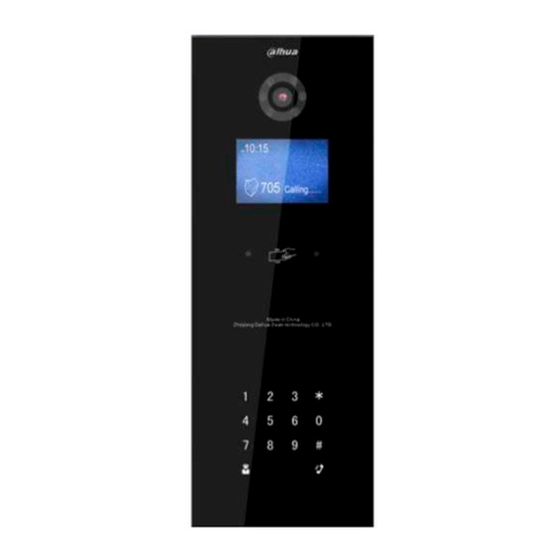
Page 12: Appearance
Appearance VTO1220A/VTO1210A-X 2.1.1 Front Panel Figure 2-1 VTO1220A/VTO1210A-X Table 2-1 Front panel description Name Description Light sensor Senses ambient light to turn on or off the fill light. Fill light Provides extra light for the camera. Inputs audio. Appearance 3... -
Page 13: Rear Panel
Name Description : Press to delete the previous character or end the current call. Numeric keys: enter numbers from 0 to 9. : Press to unlock with password. Press , then enter the unlock password, and then press Dialing area again to complete. -
Page 14: Vto1220Bw/Vto1210B-X
See "2.4.1 Access Control Input and Output Port." Analog signal port See "2.4.3 Analog Signal Port." The VTO would make alarm sound if it is being Tamper alarm removed from the wall by force, and the alarm will also be sent to the management center. -
Page 15: Rear Panel
Name Description : Press to deletes the previous character or end the current call. Numeric keys: enter numbers from 0 to 9. : Press to unlock with password. Press , then enter the unlock password, and then press Dialing area again to complete. -
Page 16: Vto1210C-X
Name Description The VTO would make alarm sound if it is being Tamper alarm removed from the wall by force, and the alarm will also be sent to the management center. Access output port See "2.4.1 Access Control Input and Output Port."... -
Page 17: Rear Panel
Name Description : Press to deletes the previous character or end the current call. Numeric keys: enter numbers from 0 to 9. : Press to unlock with password. Press , then enter the unlock password, and then press Dialing area again to complete. -
Page 18: Rs-485/Rs-482 Port
Figure 2-7 Solenoid lock connection Figure 2-8 Motor lock connection 2.4.2 RS-485/RS-482 Port This port can be used to connect to 485/422 devices. For the detailed connection method, see Figure 2-9, Figure 2-10 and Figure 2-11. Appearance 9... -
Page 19: Analog Signal Port
Figure 2-9 RS-485/RS-482 Port (1) Figure 2-10 RS-485/RS-482 Port (2) Figure 2-11 RS-485/RS-482 Port (3) 2.4.3 Analog Signal Port Analog signal port is only available on models with –X in the name, and it can be used to connect to analog devices. See Figure 2-12. Appearance 10... - Page 20 Figure 2-12 Analog signal port Appearance 11...
-
Page 21: Network Diagram
Network Diagram See Figure 3-1 for the network diagram. Figure 3-1 Network diagram Network Diagram 12... -
Page 22: Installation
4.1.2 Guidance See Figure 4-1 for the reference of the installation position. The VTO horizontal angle of view varies with different model, try to face to the center of the VTO as much as possible. Figure 4-1 Installation position reference... -
Page 23: Installing Vto
Step 4 Fix the mounting box in the opening with the ST3×18 screws. Step 5 Fix the VTO in the mounting box with the M3×16 screws. Step 6 Apply silica gel to gaps between the device and the wall. Liquid sodium silicate is recommended. -
Page 24: Vto1220Bw/Vto1210B-X
Figure 4-3 Apply silica gel to gaps 4.2.2 VTO1220BW/VTO1210B-X Figure 4-4 VTO1220BW/VTO1210B-X installation Table 4-2 Item list No. Item Item No. Item Wall Plastic mounting box Bracket ST3×18 screw M3×16 screw Step 1 Cut an opening with the size of the mounting box on the wall, and then put the mounting box in. - Page 25 Step 3 Fix the bracket on the mounting box with the ST3×18 screws. Step 4 Fix the VTO on the bracket with the M3×16 screws. Step 5 Apply silica gel to gaps between the device and the wall. Liquid sodium silicate is recommended.
-
Page 26: Vto1210C-X
Connect the ports on the rear panel to those in the wall. See the details in "2.4 Connecting Cable." Step 4 Fix the VTO in the mounting box with the M4×30 screws. Step 5 Apply silica gel to gaps between the device and the wall. - Page 27 Figure 4-7 Apply silica gel to gaps 4.2.3.2 Installing with Plastic Mounting Box Figure 4-8 VTO1210C-X with mounting box Table 4-4 Item list Item Item Wall Plastic mounting box M4×40 screw Step 1 Cut an opening with the size of the mounting box on the wall, and then put the mounting box in.
- Page 28 Connect the ports on the rear panel to those in the wall through the mounting box. See the details in "2.4 Connecting Cable." Step 3 Fix the VTO in the mounting box with the M4×40 screws. Step 4 Apply silica gel to gaps between the device and the wall.
-
Page 29: Configuration
For the detailed information, see the corresponding user's manual. Configuring VTO Connect the VTO to your PC with network cable, and for first time login, you need to create a new password for the web interface. 5.3.1 Initialization The default IP address of VTO is 192.168.1.110, and make sure the PC is in the same network... -
Page 30: Configuring Vto Number
You can change the number of a VTO when it is not working as SIP server. The VTO number can contain 5 numbers at most, and it cannot be the same as any room number. -
Page 31: Configuring Network Parameters
Step 2 Enter the network parameters you planed, and then click Save. The VTO will reboot, and you need to modify the IP address of your PC to the same network segment as the VTO to log in again. Configuration 22... -
Page 32: Configuring Sip Server
VTO. See the details in "5.3.5 Adding VTO Devices" and "5.3.6 Adding Room Number." If the VTO you are visiting does not work as SIP server, do not select the Enable check box at SIP Server, otherwise the connection will fail. -
Page 33: Adding Vto Devices
SIP server can make video call between each other. This section applies to the condition in which a VTO device works as SIP server, and if you are using other servers as SIP server, see the corresponding manual for the detailed configuration. -
Page 34: Adding Room Number
VTH devices to connect them to the network. This section applies to the condition in which a VTO device works as SIP server, and if you use other servers as SIP server, see the corresponding manual for the detailed configuration. - Page 35 Figure 5-10 Add single room number Configure room information. See Table 5-3. Table 5-3 Room information Parameter Description First Name Last Name Enter the information you need to differentiate each room. Nick Name The room number you planned. If you use multiple VTH devices, the room number of the master VTH should be "room number#0", and the room Room No.
-
Page 36: Verifying Configuration
5.4.1 Calling VTH from VTO Step 1 Dial room number on the VTO. Step 2 Press The VTO is calling the VTH. See Figure 5-12. Figure 5-12 Call screen Step 3 on the VTH to answer the call. 5.4.2 Doing Monitor from VTH Step 1 In the main interface of the VTH, select Monitor >... - Page 37 Figure 5-13 Door Step 2 Select the VTO you need to do monitor. The monitor screen is displayed. See Figure 5-14. Figure 5-14 Monitor screen Configuration 28...
-
Page 38: Operating Vto
Unlock Function 6.2.1 Unlock with IC Card Swipe the authorized access card at the access card area of the VTO to open the door. 6.2.2 Unlock with Exit Button If there is exit button connected to the VTO, press the exit button to open the door. -
Page 39: Project Mode
SIP server, see the detailed configuration in the corresponding manual. When using platform as SIP server, you need to configure the public password and duress password on the web interface of each VTO, and you can configure different password for each VTO. Project Mode... -
Page 40: Modifying Ip Address
Step 3 6.3.7 Adding Room No. You can only add room number on the VTO that works as SIP server, and then you can configure the added room number on the corresponding VTH to connect it in the network. In the project mode, select “Add Number.”...
Need help?
Do you have a question about the VTO and is the answer not in the manual?
Questions and answers