Dahua VTO4202F-P Series Quick Start Manual
Modular vto
Hide thumbs
Also See for VTO4202F-P Series:
- Quick start manual (36 pages) ,
- Quick start manual (27 pages)
Table of Contents
Advertisement
Quick Links
Advertisement
Table of Contents

Related Manuals for Dahua VTO4202F-P Series


Summary of Contents for Dahua VTO4202F-P Series
- Page 1 Modular VTO (VTO4202F-P) Quick Start Guide V1.0.1...
-
Page 2: Foreword
Foreword General This document mainly introduces product function, structure, networking, mounting process, debugging process, and web operations of modular VTO. Models VTO4202F-MK, VTO4202F-MB1, VTO4202F-MB2, VTO4202F-MB5, VTO4202F-MR, VTO4202F-MS, VTO4202F-MF, VTO4202F-ML, VTO4202F-MA, VTO4202F-P Device Upgrade Do not cut off power supply during device upgrade. Power supply can be cut off only after the device has completed upgrade and restarted. - Page 3 About the Manual The manual is for reference only. If there is inconsistency between the manual and the actual product, the actual product shall prevail. We are not liable for any loss caused by the operations that do not comply with the manual. ...
-
Page 4: Important Safeguards And Warnings
Important Safeguards and Warnings The following description is the correct application method of the device. Read the manual carefully before use, in order to prevent danger and property loss. Strictly conform to the manual during application and keep it properly after reading. Operating Requirement ... -
Page 5: Table Of Contents
Table of Contents Foreword ..............................I Important Safeguards and Warnings ....................III 1 Overview ..............................1 Introduction ........................... 1 Function ............................1 2 Structure ..............................2 Camera Module..........................2 Indicator Light Module ........................3 Audio Module ..........................4 Button Module ..........................4 Keyboard Module (with Braille) ..................... -
Page 6: Overview
Overview Introduction Modular VTO consists of camera module, indicator light module, one-button module, two-button module, five-button module, keyboard module, card swiping module, fingerprint module, audio module, and display module. Camera module and audio module are indispensable, whereas other modules can be selected as needed. The combination of modular VTO, VTH, VTS and platform makes a voice/video communication system. -
Page 7: Structure
Structure Camera Module Camera module (front panel) Table 2-1 Camera module (front panel) description Name Description Microphone Audio input. Camera Monitor area in front of the door. Speaker Audio output. Camera module (rear panel) Structure 2... -
Page 8: Indicator Light Module
Table 2-2 Camera module (rear panel) description Name Description Tamper When VTO is detached from the wall forcibly, alarm sound will be made switch and alarm information will be sent to management center. Provide power port, lock port, door sensor feedback port and exit button User port port to connect power supply, electric control lock, solenoid lock and exit button. -
Page 9: Audio Module
Indicator light module (rear panel) Table 2-4 Indicator light module (rear panel) description Name Description Cascade input port Connected to other modules. Cascade output port Audio Module Rear panel of audio module is the same as rear panel of camera module. Audio module Table 2-5 Audio module description Name... - Page 10 Five-button module (front panel) Table 2-6 Button module (front panel) description Name Description User directory Display user information according to buttons. Call the VTH and call the management center (you Call button need to do seetings on the web first). Five-button module (rear panel) Table 2-7 Button module (rear panel) description Name...
-
Page 11: Keyboard Module (With Braille)
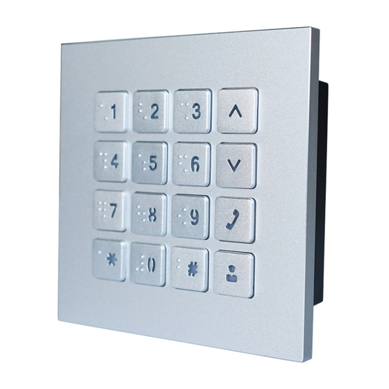
Keyboard Module (with Braille) Rear panel of keyboard module is the same as rear panel of button module. Keyboard module Table 2-8 Keyboard module description Name Description Selection buttons Press the buttons to select previous or next item. Enter the password and VTH nombers. For example, Numeric button unlock password is 123456. -
Page 12: Fingerprint Module
Fingerprint Module The module is helpful for collecting fingerprints or unlocking with fingerprint. Rear panels of fingerprint module and button module have different port positions, but port functions are the same. Fingerprint module Display Module Display module can be used for displaying user information. Rear panels of display module and button module have different port positions, but port functions are the same. -
Page 13: Blank Module
Display module Blank Module Blank module can be used for more attractive appearance when there is extra space. Rear panels of blank module and button module have different port positions, but port functions are the same. Blank module Structure 8... -
Page 14: Installation
Installation Modular VTO supports mounting two modules and three modules, and you can mount it horizontally or vertically. Depending on the actual conditions of the installation surface, you can install the VTO in the wall or on the wall. This section takes 3-module mounting for example. Visiting cards and card cover are included in the package by default. - Page 15 Apply silicone sealant to gaps Installing on the wall Installation 10...
-
Page 16: Installing In The Wall
3.1.2 Installing in the Wall Drill a hole in the wall. For 2-module mounting, the rectangular hole dimension is 126mm×226mm to 128mm×228mm. For 3-module mounting, the rectangular hole dimension is 126mm×326mm to 268mm×329mm. Put the mounting box into the wall with ST4×25 screws; ensure that box edge clings to the wall. -
Page 17: Horizontal/Vertical Mounting
Horizontal/Vertical Mounting 3.2.1 Horizontal Mounting Horizontal mounting (1) Horizontal mounting (2) When the VTO is horizontally mounted, make sure that the tamper switch on the rear panel (marked with "1" in Figure 3-4) is retracted so that once the VTO is dismantled, tamper switch will be released, and then alarms will be triggered. -
Page 18: Vertical Mounting
3.2.2 Vertical Mounting Vertical mounting illustrations When the VTO is vertically mounted, make sure that the tamper switch on the rear panel (marked with "1" in Figure 3-5) is retracted so that once the VTO is dismantled, tamper switch will be released, and then alarms will be triggered. The alarm will keep ringing for 15 seconds. Cascade Connection To make modules work collaboratively, cascade connection is needed. -
Page 19: Configuration
Configuration This chapter introduces how to initialize, connect, and make primary configurations to the VTO and VTH devices to realize basic functions, including device management, calling, and monitoring. For more detailed configuration, see the user's Manual. Configuration Process Before configuration, check every device and make sure that there is no short circuit or open circuit in the circuits. -
Page 20: Configuring Vto Number
Device initialization Enter and confirm the password, and then click Next. The Email setting interface is displayed. Select the Email check box, and then enter your Email address. This Email address can be used to reset the password, and it is recommended to finish this setting. Click Next. -
Page 21: Configuring Network Parameters
Log in to the web interface of the VTO, and then the main interface is displayed. See Figure 4-3. Main interface Select Local Setting > Basic. The device properties are displayed. See Figure 4-4. Device properties In the VTO No. input box, enter the VTO number you planned for this VTO, and then click Confirm to save. -
Page 22: Selecting Sip Servers
TCP/IP information Enter the network parameters you planed, and then click Save. The VTO will restart, and you need to modify the IP address of your PC to the same network segment as that of the VTO to log in again. 4.2.4 Selecting SIP Servers The Session Initiation Protocol (SIP) is used for signaling and controlling multimedia communication sessions in applications of voice and video calls. - Page 23 Device properties Select TCP/IP from the System Type drop-down list. Default system type is analogue system and shall be changed to TCP/IP. Otherwise, it will fail to be connected to the VTH. Click OK to save the settings. Restart the device manually, or wait for auto reboot to make the settings effective. Log in to the web interface again.
- Page 24 Platform (Express/DSS) as a SIP server Select Network Setting > SIP Server. The SIP Server interface is displayed. See Figure 4-8. SIP server (2) Disable SIP Server. Select Express/DSS from the Server Type drop-down list. Set parameters according to Table 4-1. Table 4-1 SIP server parameter description Parameter Description...
-
Page 25: Adding Vto Devices
Parameter Description select the Enable checkbox to enable the alternate server. After you have selected the Alternate Server Enable checkbox, you can only enter the VTS IP address, and the VTO will restart. Click OK to save the configuration. The VTO will restart automatically. When the platform works as SIP server, if it is necessary to set Building No. -
Page 26: Adding Room Number
Add VTO Configure the parameters, and be sure to add the SIP server itself too. See Table 4-2. Table 4-2 VTO configuration Parameter Description The VTO number you configured for the target VTO. See the details Rec No. in "4.2.2 Configuring VTO Number." Register Password Keep default value. - Page 27 Room No. management You can add single room number or do it in batches. Adding single room number Click Add. See Figure 4-11. The Add interface is displayed. See Figure 4-12. Add single room number Configure room information. See Table 4-3. Table 4-3 Room information Parameter Description...
-
Page 28: Configuring Module
Parameter Description Nick Name The room number you planned. If you use multiple VTH devices, the room number of the master VTH Room No. should be "room number#0", and the room number of the extension VTH should be "room number#1", "room number#2", …, "room number#99". - Page 29 Faç ade layout Click The system displays the modules available. Keyboard module, card swiping module, and fingerprint module will not be displayed if they have been added. Select modules according to actual layout of VTO. Actual connection position of the device on web interface is from top to bottom and from left to right.
- Page 30 Set modules Click The Room List interface is displayed. See Figure 4-16. The room no. displayed on the interface corresponds to the added VTH. "888888" is the Centre Call No. Room list Configuration 25...
-
Page 31: Verifying Configuration
Select room no. and click Save. The interface displays room No. information. See Figure 4-17. Room No. information Click Confirm, and then restart the browser to make the configurations take effective. save the settings. Verifying Configuration 4.3.1 Calling VTH from VTO Dial room number on the VTO. -
Page 32: Doing Monitor From Vth
Call screen on the VTH to answer the call. 4.3.2 Doing Monitor from VTH On the main interface of the VTH, select Monitor > Door. The Door interface is displayed. See Figure 4-19. Door Select the VTO you need to do monitor. The monitor screen is displayed. - Page 33 Monitor screen Configuration 28...
-
Page 34: Cybersecurity Recommendations
Cybersecurity Recommendations Cybersecurity is more than just a buzzword: it’s something that pertains to every device that is connected to the internet. IP video surveillance is not immune to cyber risks, but taking basic steps toward protecting and strengthening networks and networked appliances will make them less susceptible to attacks. - Page 35 Change Default HTTP and Other Service Ports We suggest you to change default HTTP and other service ports into any set of numbers between 1024~65535, reducing the risk of outsiders being able to guess which ports you are using. Enable HTTPS We suggest you to enable HTTPS, so that you visit Web service through a secure communication channel.
- Page 36 The network should be partitioned and isolated according to the actual network needs. If there are no communication requirements between two sub networks, it is suggested to use VLAN, network GAP and other technologies to partition the network, so as to achieve the network isolation effect. ...
Need help?
Do you have a question about the VTO4202F-P Series and is the answer not in the manual?
Questions and answers