Table of Contents
Advertisement
Quick Links
Advertisement
Table of Contents

Subscribe to Our Youtube Channel
Related Manuals for Dahua VTO12 Series


Summary of Contents for Dahua VTO12 Series
- Page 1 Unit Door Station User's Manual ----VTO12XX Series V1.2.0...
- Page 2 Welcome Thank you for purchasing our product! This quick start guide is designed to be a reference tool for your system. Please keep it well for future reference!
- Page 3 Important Safeguards and Warnings Please read the following safeguards and warnings carefully before using the product in order to avoid damages and losses. Note: Do not expose the device to lampblack, steam or dust. Otherwise it may cause fire or electric shock. Do not install the device at position exposed to sunlight or in high temperature.
-
Page 4: Table Of Contents
Table of Contents Product Overview ..................1 VTO1210A/VTO1210A-X/VTO1220A .............. 1 VTO1210B(W)-X/VTO1220B(W) ..............4 VTO1210C-X ....................6 Basic Functions ................... 9 Call........................9 Modify Local Config ..................9 2.2.1 Enter Project Settings Interface ............. 9 2.2.2 Modify IP, Gateway and Subnet Mask........... 9 2.2.3 Modify Volume Config ................. - Page 5 Debug Digital System ..................21 4.1.1 Configure VTO ..................21 4.1.2 Configure Digital VTH ................. 22 4.1.3 Create Digital System ................. 22 Debug Analog System................... 22 4.2.1 Configure VTO ..................23 4.2.2 Create Analog System ................ 23 4.2.3 Configure Analog VTH ................ 23 FAQ ......................
-
Page 6: Product Overview
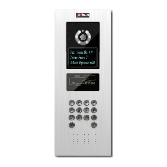
1 Product Overview Connect the device to the power, the system boots up properly. After about one minute, the screen turns on and the boot-up completes, system goes to the normal working interface. The front panel is shown as in Figure 1-1, Figure 1- 2 and Figure 1-3. 1.1 VTO1210A/VTO1210A-X/VTO1220A Figure 1- 1 VTO1210A/VTO1210A-X/VTO1220A Please refer to the following sheet for detailed information. - Page 7 It can compensate the camera light in Compensation Light the low illumination environments. Microphone Audio input Button. Backspace function. It is to delete the previous symbol. Hang up function. It is to hang up the call. 2. Number button. Input the number 0 to button.
- Page 8 password. Please press the button to confirm. Camera It is to monitor the video of the door.
-
Page 9: Vto1210B(W)-X/Vto1220B(W)
1.2 VTO1210B(W)-X/VTO1220B(W) Figure 1- 2 VTO1210B(W)-X/VTO1220B(W) Please refer to the following sheet for detailed information. Name Function Logo Printed logo. Microphone Audio input It can compensate the camera light in Compensation Light the low illumination environments. Approaching It can detect approaching body. Induction... - Page 10 Speaker Output audio Button. Backspace function. It is to delete the previous symbol. Hang up function. It is to hang up the call. 2. Number button. Input the number 0 to button. When you are using the Key Panel password to open the door. Press this button once to begin input.
-
Page 11: Vto1210C-X
Camera It is to monitor the video of the door. 1.3 VTO1210C-X Figure 1- 3 VTO1210C-X Please refer to the following sheet for detailed information. Name Function Logo Printed logo. Microphone Audio input It can compensate the camera light in Compensation Light the low illumination environments. - Page 12 Button. Backspace function. It is to delete the previous symbol. Hang up function. It is to hang up the call. 2. Number button. Input the number 0 to button. When you are using the password to open the door. Press this button once to begin input.
- Page 13 password. Please press the button to confirm. Camera It is to monitor the video of the door.
-
Page 14: Basic Functions
2 Basic Functions 2.1 Call Under standby status (Figure 1-1, Figure 1- 2), press button, this VTO will call center. The video door phone begins when the port picks up. During the whole process, you can press the button to end current talk and return to the standby interface. -
Page 15: Modify Volume Config
2.2.3 Modify Volume Config In volume interface, adjust volume via button 4 and 6. When you finish, press to exit modification interface. 2.3 Issue Card In card issuing interface, select to issue card with parent card or password via button 2 and 8. -
Page 16: Unlock Via Ic Card
password: 123456, press to unlock. For example, to unlock room 101, you shall input: #0101123456#. Defualt password can be changed in A&C Manager interface. 2.4.3 Unlock via IC card The door is open after you swipe IC card and the card passed the authentication and station verification. -
Page 17: Web Function
3 Web Function 3.1 Overview The web-based interface is shown in Figure 3- 1. Web function supports VTO1220A, VTO1220B, VTO1210A-X, VTO1210B(W)-X and VTO1210C-X. The webpage of each device may be slightly different. Here makes 1210B-X an example: Figure 3- 1 Please refer to the following sheet for detailed information. -
Page 18: System Config
3.2 System Config 3.2.1 Login Config Input VTO IP address in address field of IE Explorer as in Figure 3- 2. Figure 3- 2 You must input username and password in order to login WEB main interface. Default username: admin Default password: admin. - Page 19 Figure 3- 3 3.2.1.2 A&C Manager Click on Local Config and then click on A&C Manager. You may change password here and please keep in mind that the default password is 123456. To unlock door, please input #123456#. You also can set unlock responding interval and unlock period. FTP address: FTP address is used to store snapshot taken at VTO when someone swipes card.
-
Page 20: Indoor Station(Vth) Manager
3.2.2.3 System Time Click on Local Config and then click on System Time. You may set time in the following interface as in Figure 3- 5. You may also synchronize system time with your local PC. Figure 3- 5 3.2.2 Indoor Station(VTH) Manager Indoor Station Manager mainly includes adding digital/analog VTH, deleting VTH and editing VTH user. -
Page 21: Lan Setting
Figure 3- 6 3.2.3.2 Analog Indoor Station Manager In Analog Indoor Station Manager interface, check box display resident info enable to display successfully configured VTH info as shown in Figure 3- 7. Click on add button at the left lower corner, and input VTH number, distributor address and distributor port. VTH number is the room number where analog VTH locates;... -
Page 22: Network Setting
want to set the center, you need to change default settings to be identical with center info. You also need to check box register to MGT center. If you successfully set center, you may call center by pressing call center button at lower left corner on VTO. -
Page 23: Change Password
Figure 3- 9 3.2.5 Change Password In Change Password interface, you can change WEB login password of VTO. You must input old password, new password and confirm new password. Click on OK button to save as shown in Figure 3- 10. Figure 3- 10 3.3 Info Search Click on Info Search and then click on Call History. -
Page 24: Status Statistics
Figure 3- 11 3.4 Status Statistics Click on Status Statistics and then click on VTH Status. Here you can view connection status of VTH as shown in Figure 3- 12. Figure 3- 12 3.5 Logout Click on Logout. Here you may select either to Reboot Device or Logout system as shown in Figure 3- 13 and Figure 3- 14. - Page 25 Figure 3- 13 Figure 3- 14...
-
Page 26: Debug System
4 Debug System 4.1 Debug Digital System See Figure 4- 1. Figure 4- 1 Connect VTO to PC via network connection and modify PC’s local IP, subnet mask to be the same network segment of VTO. You can access and configure the VTO via web. 4.1.1 Configure VTO Enter VTO’s WEB page—Local Config (Figure 3-3), set System Type to TCP/IP and Video Format to WVGA (If the VTH is 1520A-A8, then set it to D1.). -
Page 27: Configure Digital Vth
4.1.2 Configure Digital VTH Enter digital VTH system settings—Project Settings, input project password: 002236 to enter. Input the room no. that configured on VTO. In Network Config, configure VTH IP, Subnet Mask and Default Gateway. At network terminal, input VTO IP address, enable it and click on OK. -
Page 28: Configure Vto
Connect VTO to PC via network connection, and change PC’s local IP, subnet mask to be the same network segment of VTO. You can access and configure the VTO via web. 4.2.1 Configure VTO Enter VTO’s WEB page—Local Config (Figure 3-3), set System Type to analog and Video Format to D1. -
Page 29: Faq
5 FAQ Q: I cannot boot up the device, or I can see the LCD is black. A: Please check your power cable connection. Please reboot it again. Q: I cannot call. A: Please check your network connection. Q: I cannot reach the person I want to contact. What shall I do? A: It may be the network error. -
Page 30: Appendix 1 Specifications
Appendix 1 Specifications Model VTO1210A VTO1220A VTO1220B(W) VTO1210A-X VTO1210B(W)-X VTO1210C-X Main Processor Embedded micro processor Embedded LINUX OS Video Video Compression Standard H.264 Input/Approaching Induction 1.3 megapixel CMOS camera Back Light Support Auto Light Compensation Support Audio Input Microphone Output Built-in speaker Bidirectional Talk Support dual-way bidirectional talk... - Page 31 Others Power DC 10~15V Power Consumption Standby≤1W ;work≤10W -10℃ -10℃ -20℃~+60℃ -40℃~+60℃ Working Environments ~+60℃ ~+60℃ 10~95%RH Water Proof VTO1212B-X Water proof level:IP65 Dimensions 376mm*151mm*60mm(L*W*H) Weight 1.6kg...
-
Page 32: Appendix 2 Device Port
Appendix 2 Device Port The device rear panels are shown as in Figure 2-1 and 2-2. Figure 2-1 VTO1210A/VTO1220A/VTO1210A-X rear structure Port Name Function Network Port Connect to the RJ45 port. Connect to signal from the door sensor, door on/off signal. Access Control Input Port... - Page 33 Connect to the analog signal of the distributor. Analog Signal Port corresponds (VTO1210A-X only) Vandal Proof Alarm It can generate an alarm when there is Button a vandal operation. Connect to RS422 or RS485 Communication Device. RS422 Port (Reserved)
- Page 34 Power Port Connect to 12V DC. Control NO/NC of door lock. Access Control Output Port Figure 2- 1 VTO1210B(W)-X/VTO1210C-X/VTO1220B(W) rear structure Please refer to the following sheet for detailed information.
- Page 35 SN Port Name Function Vandal Proof Alarm Button It can generate an alarm when there is a vandal operation. Network Port Connect to the RJ45 port. Connect to signal from the door sensor, door on/off signal. Access Control Input Port Power Port Connect to 12V DC power.
-
Page 36: Appendix 3 Installation
Appendix 3 Installation Please refer to the following sheet for detailed installation information. Please see Figure 3- 1 and Figure 3- 2 VTO1210B-X/VTO1220B installation guide. Figure 3- 1 VTO1210A/VTO1210A-X/VTO1220A installation guide... - Page 37 Figure 3- 2 VTO1210B-X/VTO1220B installation guide...
- Page 38 Figure 3- 3 VTO1210C-X installation guide Note: This manual is for reference only. Slight difference may be found in user interface. All the designs and software here are subject to change without prior written notice. All trademarks and registered trademarks are the properties of their respective owners.
Need help?
Do you have a question about the VTO12 Series and is the answer not in the manual?
Questions and answers