Dahua VTO1220A User Manual
Hide thumbs
Also See for VTO1220A:
- Quick start manual (39 pages) ,
- User manual (38 pages) ,
- User manual (49 pages)
Table of Contents
Advertisement
Quick Links
Advertisement
Table of Contents

Related Manuals for Dahua VTO1220A


Summary of Contents for Dahua VTO1220A
- Page 1 VTO1210C_X User's Manual V1.0.0...
- Page 2 Welcome Thank you for purchasing our product! This quick start guide is designed to be a reference tool for your system. Please keep it well for future reference!
- Page 3 Important Safeguards and Warnings Please read the following safeguards and warnings carefully before using the product in order to avoid damages and losses. Note: Do not expose the device to lampblack, steam or dust. Otherwise it may cause fire or electric shock. Do not install the device at position exposed to sunlight or in high temperature.
-
Page 4: Table Of Contents
Table of Contents Product Overview ....................1 Product Introduction ..................1 Features ......................1 VTO1210C-X Structure ..................2 Front Panel ..................... 2 Rear Panel (Ports) ..................4 Typical Networking ..................... 6 Install VTO ......................7 Installation Illustration ..................7 Screw ......................7 Installation Steps ..................... - Page 5 6.2.1 Local Config ..................14 6.2.2 LAN Config ..................19 6.2.3 Indoor Manager ................... 19 6.2.4 Network Config ................... 21 6.2.5 Video Set .................... 22 6.2.6 User Manage ..................23 6.2.7 IPC Info ....................24 6.2.8 VTO Info ..................... 25 6.2.9 IP Auto Allocation ................
-
Page 6: Product Overview
1 Product Overview 1.1 Product Introduction Unit VTO is part of video talk system, and it connects to VTH, providing a bidirectional video talk between visitor and resident for the purpose of dual identification of image and audio. 1.2 Features ... -
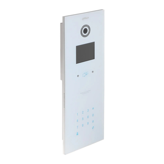
Page 7: Vto1210C-X Structure
2 VTO1210C-X Structure 2.1 Front Panel Plug to power, system boots up and wait for 1 minute, screen turns on. System enters working interface, see Figure 2- 1. Figure 2- 1 Please refer to the following sheet for detailed information. Name Function Logo... - Page 8 button. When you are using the password to open the door. Press this button once to begin input. After you input the password, please press it again to complete the operation. Call button. After you input the room number, press it to begin a dial up. Call MGT center button.
-
Page 9: Rear Panel (Ports)
2.2 Rear Panel (Ports) Figure 2- 2 Please refer to the following sheet for detailed information. Port Name Function Vandal Proof Alarm It can generate an alarm when there is a vandal Button operation. Network Port Connect to the RJ45 port. Connect to signal from the door sensor, door on/off signal. -
Page 11: Typical Networking
3 Typical Networking Please read the following contents carefully, and install with a rational networking plan. Network Note: VTO network port (dual network VTO is in Figure 2- 2 no. network port) connects to switch IN port. Select any one network port from switch’s port 1 to 6 to connect to VTH. The switch will supply power to VTH. -
Page 12: Install Vto
4 Install VTO Unit VTO on-site installation includes: wall embedded installation, door embedded installation (with box/without box), standalone installation. This chapter will introduce wall embedded installation of VTO1210C-X series. 4.1 Installation Illustration Figure 4- 1 4.2 Screw Component Illustration Quantity M4×40 inner hex flower countersunk flat head screws-stainless steel... -
Page 13: Installation Steps
4.3 Installation Steps Step 1. Embed plastic housing into wall. Step 2. Fix device on the bracket with screw. 4.4 Wiring Please refer to Figure 2- 2. -
Page 14: Basic Functions
5 Basic Functions 5.1 Local Config You can configure the device on VTO, including IP setup, audio setup and issue card. You can view VTO version information as well. 5.1.1 IP Setup You can set IP address, network gateway, subnet mask and etc. in IP setup interface. Step 1. -
Page 15: Issue Card
5.1.3 Issue Card Before issuing card, please ensure the connection between VTH and VTO, and VTH is added on WEB-end of VTO. The detailed steps to add VTH is in Ch 6.2.3. Card issuing setup includes password and main card. You can set right of issuing card in card issuing interface. -
Page 16: Version
authorize more cards, or press “ ” to exit. You swipe the card at card swiping area, and the system prompts the process is successful. 5.1.4 Version You can view version of the device on VTO, including man program version and MCU version. -
Page 17: Unlock Via Password
5.2.2 Unlock via Password Before you can unlock door via password, you must configure the password on VTO WEB-end, please refer to Ch 6.2.1.2. Uniform password: In standby interface, for example your password is “123456”, then press “ +123456+ to unlock. -
Page 18: Web Function
6 Web Function Warning: Before you access unit VTO WEB interface via PC, please make sure the PC and unit VTO are both connected to the Internet and are in the same network segment. Otherwise, you cannot access. Before you access unit VTO WEB interface via PC, please make sure you have set VTO IP address, please refer to Ch 5.1.1. -
Page 19: System Logout
6.1.2 System Logout Step 1. Select Logout>Logout to exit system. See Figure 6- 2. Figure 6- 2 Step 2. Select Logout>Reboot Device to reboot the device. See Figure 6- 3. Figure 6- 3 6.2 System Config System Config includes Local Config, LAN Config, Indoor Manager, Network Config, Video Set, User Manage, IPC Information and others. - Page 20 Figure 6- 4 Parameter Note System Type System type is digital and analog. Sensor Set compensation light sensor sensitivity, input number within 0~255. The higher the value, the higher the sensitivity will Storage Point Record, snapshot and other info can be stored in FTP server and SD card.
- Page 21 Figure 6- 5 For detailed VTH operations. Refer to Ch 6.2.3. 6.2.1.2 A&C Manager A&C manager mainly includes unlock via password, unlock response interval and hold time, unlock info upload and auto snapshot. See Figure 6- 6. Figure 6- 6 Parameter Note Unlock...
- Page 22 Signal Before Lock”, valid only when “door sensor check time” is Signal Before Lock set. Issue Card Password Issue card password is 123456 by default, may be changed. Project Password Enter project setup interface with this password, it is 888888 by default, may be changed.
- Page 23 Figure 6- 8 6.2.1.5 Config Manager User can import and export config, and restore default settings. See Figure 6- 9. Figure 6- 9 Parameter Note Check “card info”, “VTH info”, then click Backup to backup card no. and Backup VTH info. Restore Backup Check card info, vth into, and click on Restore Backup to restore default card info and vth info.
-
Page 24: Lan Config
Indoor Station Manager mainly includes adding digital/analog VTH, deleting VTH and editing VTH user. VTO1210A-X and VTO1210B-X have digital and analog indoor station manager. VTO1220A only has digital indoor station manager. For example, to add digital VTH. Step 1. In page, select System Config>Indoor Manager>Digital Indoor Station. - Page 25 Figure 6- 11 Parameter Note Setup For example, 1101. “11” means VTH short VTH short no. is room no., floor 11 while “01” means room composed of 4 digits of number. Note: VTH short no. first two digits range is 01~99. Last two digits range is 01~16.
-
Page 26: Network Config
Figure 6- 13 Main card: Set a card to main card, and you may issue new card via the main card, see Ch 5.1.3.1. Lost card: report card loss, and make up with a new card before you can swipe card to enter. -
Page 27: Video Set
Figure 6- 14 Step 3. Click OK. After you modify IP address, the WEB page will go to the new address automatically. 6.2.5 Video Set Please follow prompt in video to install video control unit. Step 1. Select System Config>Video Set. Step 2. -
Page 28: User Manage
Unlock Click on unlock to remotely unlock door lock. Step 3. Click Audio Set tab to adjust audio parameter. Figure 6- 16 6.2.6 User Manage Only when you login as admin, you can add, modify, delete and view user information. System currently supports two types of user: ... -
Page 29: Ipc Info
Step 3. In pop-up box fill in user info. Step 4. Click OK. 6.2.6.2 Modify/Delete User Admin and system support password change, but cannot change note information or delete the username. Step 1. Select System Config>User Manager. See Figure 6- 18. Figure 6- 18 Step 2. -
Page 30: Vto Info
Step 2. Select System Config>IPC Information. Step 3. In IPC Information interface, click on System pops up a box, modify IPC information. See Figure 6- 20. Figure 6- 20 Step 4. Click OK. 6.2.8 VTO Info Step 1. Select System Config>VTO Info. Step 2. -
Page 31: Ip Auto Allocation
Fence station VTO Middle Number IP Address Set IP address of the VTO. Step 4. Check Enable. Step 5. Click OK. 6.2.9 IP Auto Allocation You can go to User Manager>IP Allocate Auto interface, set VTH IP address, subnet mask, default gateway and etc. -
Page 32: Info Search
See Figure 6- 23. Figure 6- 23 Step 3. Click Send. 6.2.10.2 History Info Step 1. Select System Config>Publish Information>History Info. See Figure 6- 24. Figure 6- 24 Step 2. You can view historical information, click on to delete ifnormation. 6.3 Info Search You can view call record, alarm record and swiping card record. -
Page 33: Call History
6.3.1 Call History Step 1. In page, select Info Search>Call History. You can search VTO call records and the system can store up to 1124 records. See Figure 6- 25. Figure 6- 25 Call type: outgoing. End status: Received and missed. Step 2. -
Page 34: Status Statistics
Figure 6- 27 Step 2. Click on Export Record to save record to local.. 6.4 Status Statistics By selecting Status Statistics>VTH Status. You can view connection status of VTH. See Figure 6- 28. Figure 6- 28... -
Page 35: Appendix 1 Specifications
Appendix 1 Specifications Model VTO1220A VTO1220B(W) VTO1210A-X VTO1210B(W)-X VTO1210C-X Main Processor Embedded micro processor Embedded LINUX OS Video Video Compression Standard H.264 Input/Approaching Induction 1.3 megapixel CMOS camera Back Light Support Auto Light Compensation Support Audio Input Microphone Output Built-in speaker... - Page 36 Water Proof IP53 IP65 IP53 IP65 IP53 Note: This manual is for reference only. Slight difference may be found in user interface. All the designs and software here are subject to change without prior written notice. All trademarks and registered trademarks are the properties of their respective owners.
Need help?
Do you have a question about the VTO1220A and is the answer not in the manual?
Questions and answers