Table of Contents
Advertisement
Advertisement
Table of Contents

Related Manuals for Dahua DHI-VTO2000-A-2-S


Summary of Contents for Dahua DHI-VTO2000-A-2-S
- Page 1 VTO Series User’s Manual Dahua Technology Co., Ltd...
-
Page 2: Foreword
General This manual offers reference material and general information about the basic operation, maintenance, and troubleshooting for a Dahua security device. Read, follow, and retain the following safety instructions. Heed all warning on the unit and in the operating instructions before operating the unit. - Page 3 Please contact the customer service for the latest program and supplementary documentation. Video loss is inherent to all digital surveillance and recording devices; therefore Dahua cannot be held liable for any damage that results from missing video information. To minimize the occurrence of lost digital information, Dahua recommends multiple, redundant recording systems, and adoption of backup procedure for all data.
-
Page 4: Important Safeguards And Warnings
Important Safeguards and Warnings This chapter describes the contents covering proper handling of the device, hazard prevention, and prevention of property damage. Read these contents carefully before using the device, comply with them when using, and keep it well for future reference. Installation and Maintenance Professionals Requirements All installation and maintenance professionals must have adequate qualifications or ... - Page 5 have the same characteristics as the original parts. Unauthorized parts may cause fire, electrical shock, or other hazards. Dahua is not liable for any damage or harm caused by unauthorized modifications or repairs. Perform safety checks after completion of service or repairs to the unit.
- Page 6 Use attachments and accessories only specified by the manufacturer. Any change or modification of the equipment, not expressly approved by Dahua, could void the warranty. Internal and external ground connection should be stable. Do not supply power via the Ethernet connection (PoE) when power is already supplied ...
-
Page 7: Cybersecurity Recommendations
Cybersecurity Recommendations Mandatory actions to be taken towards cybersecurity Change Passwords and Use Strong Passwords The number one reason systems get “hacked” is due to having weak or default passwords. It is recommended to change default passwords immediately and choose a strong password whenever possible. - Page 8 Change ONVIF Password Older IP camera firmware does not automatically change the ONVIF password when the system credentials are changed. Update the camera’s firmware to the latest revision or manually change the ONVIF password. Forward Only Ports You Need ...
- Page 9 Isolate NVR and IP Camera Network Ensure that the network for the NVR and IP cameras should not be the same network as a public computer network. Separate networks prevent unauthorized users accessing the same network the security system. Secure Auditing ...
-
Page 10: Table Of Contents
Table of Contents Foreword ..............................I Important Safeguards and Warnings ....................III Cybersecurity Recommendations ......................VI Table of Contents ............................ IX 1 Overview ..............................1 2 VTO Panels ............................. 2 VTO2000A-S / VTO2000A-2-S ..................... 2 VTO1201C-X-S ..........................4 2.2.1 Access Control Input and Output Port ................5 2.2.2 RS-485 / RS-422 Connection ..................... - Page 11 Table of Contents X...
-
Page 12: Overview
Overview Dahua VTO Intercom devices allow tenants to view and talk with visitors and remotely unlock doors all from an intuitive mobile app and an interior color indoor monitor. Each outdoor station includes a 1.3 MP wide angle camera with manual rear pivot, two-way talk and enables remote functions such as snapshot when ringing and the ability to record video and audio messages to a VTH series monitor. -
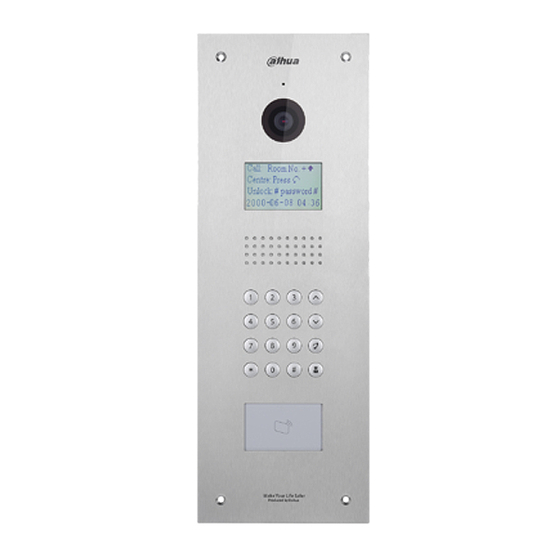
Page 13: Vto Panels
VTO Panels Use this process to plan, install, and configure the security network and the IP devices. VTO2000A-S / VTO2000A-2-S The DHI-VTO2000A-S/VTO2000-A-2-S allows tenants to view and talk with visitors and remotely unlock doors all from an intuitive mobile app and an interior color indoor monitor. Each IP outdoor station includes a 1.3 MP wide angle camera with manual rear pivot, two-way talk and enables remote functions such as snapshot when ringing and the ability to record video and audio messages to a VTH series monitor. - Page 14 Rear Panel Name Description Camera angle Adjusts camera angle. adjustment The VTO would make alarm sound if it is being Tamper alarm removed from the wall by force, and the alarm will also be sent to the management center. Connects to the network with Ethernet cable. Ethernet port For VTO2000A-2, this is a two-wire port.
-
Page 15: Vto1201C-X-S
VTO1201C-X-S Front Panel Name Description Microphone Audio input Light Provides extra light for the camera. Speaker Audio outputs. • *: End the call or delete the previously entered character. • 0 – 9: Use to enter room number or password. •... -
Page 16: Access Control Input And Output Port
Rear Panel Name Description VTO sounds an alarm and sends an alert to the Tamper alarm management office if it is being removed from the wall by force. Access output port Used to connect to door locks. Ethernet port Connects to the network via an Ethernet cable. Access input port Used to connect to door locks. - Page 17 Electronic Control Lock Connections Solenoid Lock Connection Motorized Lock Connection...
-
Page 18: Rs-485 / Rs-422 Connection
2.2.2 RS-485 / RS-422 Connection Use this port to connect to RS-485/RS-422 devices. RS-485/RS-422 Port 1 RS-485/RS-422 Port 2 RS-485/RS-422 Port 3... -
Page 19: Analog Signal Port
2.2.3 Analog Signal Port Use the analog signal port to connect to analog devices. DHI-VTO2111D-WP-S Front Panel Name Description Microphone Audio input. Camera Monitors door area. Access card reader Recognizes access cards and unlocks a door. Indicator Light Steady Blue: Standby status Flashing Blue: Network offline Call Button Call a VTH unit or the management center. - Page 20 Rear Panel Name Description Bracket Position Bracket used to fix device and wall. Switch sounds an alarm if the VTO is forcibly removed Vandal-proof Switch from the wall. Alarm Input/output One (1) Channel alarm input Interface • Quick press to reset the WiFi signal. RESET Key •...
-
Page 21: Dhi-Vto2111D-Wp-S Wiring
2.3.1 DHI-VTO2111D-WP-S Wiring... -
Page 22: Installation
Installation Requirements Do not install the VTO to places with condensation, high temperature, grease or dust, chemical corrosion, direct sunlight, or zero shelter. The installation and adjustment must be finished by a professional installer, and do not disassemble the VTO. Installation Guidance The VTO horizontal angle of view varies with different model, try to face to the center of the VTO as much as possible. -
Page 23: Installing The Vto200A-S / Vto2000A-2-S
Installation and commissioning shall be performed by professional integrators trained on the latest security devices. DO NOT dismantle or repair the device. Contact your local Dahua representative in case of a faulty device. 3.4.1 Wall Installation Drill screw holes on the wall according to those on the mounting bracket, and then insert the expansion. -
Page 24: Flush-Mount Installation
3.4.2 Flush-mount Installation Cut an opening with the size of the mounting box on the wall, and then put the mounting box in. Connect the ports on the rear panel to those in the wall through the mounting box. Fix the VTO in the mounting box with the M3×8 screws. -
Page 25: Installing The Vto1210C-X-S
Installing the VTO1210C-X-S 3.5.1 Wall Mount Name Name M4 x 30 Screws VTO Unit ST4.2 x 25 Screws Mount Box Wall Drill screw holes on the wall according to the position of the screw holes on the mounting box, and then put the expansion tubes in the screw holes. Fix the mounting box on the wall with the ST4.2×25 screws. -
Page 26: Flush-Mount
3.5.2 Flush-mount Name Name Wall Plastic Flush-mount Box VTO Unit M4 x 40 Screws Cut an opening with the size of the mounting box on the wall, and then put the mounting box in. Connect the ports on the rear panel to those in the wall. Refer to Section 2.2.2 Access Control Input and Output Port. -
Page 27: Installing The Dhi-Vto2111D-Wp-S
Installing the DHI-VTO2111D-WP-S Name Name Screw Hole Wall Anchor Mounting Screws Set Screw Bracket Seal Use the mounting bracket as a guide to drill the holes into the installation surface. Insert a wall anchor into each hole. Attach the mounting to the wall using the mounting screws. Attach the VTO unit to the bracket using the set screw. -
Page 28: Main Interface
Main Interface Log in to the VTO Web interface. Function Description These buttons are always available. Click to change the password and the Email address. General Click to enter the Main interface. function Click to log out, reboot the VTO or to restore the VTO to factory settings. -
Page 29: Configuration
Configuration Confirm that all devices are complete and that they work properly prior to installation and configuration. Setup Prior to commissioning and configuring the VTO unit, ensure the unit conforms to the following: Check that the unit is connected to the proper power supply. Power on the device only ... -
Page 30: Initialization
5.4.1 Initialization The default IP address of VTO is 192.168.1.110, and make sure the PC is in the same network segment as the VTO. Connect the VTO to power source, and then boot it up. Open the Internet browser on the PC, then enter the default IP address of the VTO in the address bar, and then press Enter. -
Page 31: Configuring The Vto Number
5.4.2 Configuring the VTO Number Configure the VTH network information. The VTH must be part of the same network segment as the VTO and the other VTH devices in the system. You can change the number of a VTO when it is not working as SIP server. ... -
Page 32: Configuring Network Parameters
In the VTO No. input box, enter the VTO number you planned for this VTO, and then click Confirm to save. 5.4.3 Configuring Network Parameters Select Network Setting > Basic. Enter the network parameters you planed, and then click Save. The VTO will reboot, and you need to modify the IP address of your PC to the same network segment as the VTO to log in again. -
Page 33: Configuring Call Number And Group Call
Set the parameters for the SIP server using the following information. Parameter Description IP Addr. The IP address of the VTO which works as SIP server. Port 5060 Username Keep the default value. Password SIP Domain SIP Server Username The user name and password for the web interface of the SIP server. -
Page 34: Adding Vto Devices
Adding VTO Devices Add the VTO devices to the SIP server, and all the VTO devices connected to the same SIP server can make video call between each other. This section details a VTO device working as a SIP server. Log in the web interface of the SIP server, and then select Household Setting >... -
Page 35: Adding A Room Number
Configure the parameters, and be sure to add the SIP server. Parameter Description The VTO number you configured for the target VTO. See the Rec No. details in "4.3.2 Configuring VTO Number." Register Password Keep the default value. Build No. Available only when other servers work as SIP server. - Page 36 Click the Add. Configure room information. Parameter Description Rec No. The VTO number you configured for the target VTO. First Name Last Name Enter the information you need to differentiate each room. Nick Name • If you use multiple VTH devices, the room number of the master VTH should be "room number#0", and the room number of the extension VTH should be "room number#1", Room No.
-
Page 37: Verifying The Configuration
Verifying the Configuration 5.6.1 Calling a VTH from the VTO Press the call button on the VTO. Tap the Answer button on the VTH to answer the call. 5.6.2 Monitoring from the VTH In the main interface of the VTH, select Monitor > Door. Select the VTO you need to do monitor. -
Page 38: Connecting To Mobile App
Connecting to Mobile App Download the mobile phone app and then add the VTO devices to the app. When someone is calling you from a VTO, there will be push message on your phone, and you can talk to the visitor or unlock the door remotely on your phone. - Page 39 Tap the "+" sign to add device, and the tap Add Device > P2P. Give a name to your target VTO, and then tap the sign. The mobile phone starts to scan. Log in the web interface of the VTO you need to add, and then select Network.
- Page 40 Scan the QR code with your phone, then enter the user name and password of its web interface, and then tap Start Live Preview. The live video is displayed. And you can also start audio intercom or unlock the door. Tap Alarm Manager >...
- Page 41 When someone calls from the subscribed VTO, there will be push message on your phone.
- Page 42 Dahua Technology USA 23 Hubble Irvine, CA 92618 Tel: (949) 679-7777 Fax: (949) 679-5760 Support: 877-606-1590 Sales: sales.usa@dahuatech.com Support: support.usa@dahuatech.com...
Need help?
Do you have a question about the DHI-VTO2000-A-2-S and is the answer not in the manual?
Questions and answers