Table of Contents
Advertisement
Quick Links
Advertisement
Table of Contents

Related Manuals for Dahua VTO12 Series


Summary of Contents for Dahua VTO12 Series
- Page 1 VTO12XX Series User's Manual V1.2.0...
- Page 2 Welcome Thank you for purchasing our product! This quick start guide is designed to be a reference tool for your system. Please keep it well for future reference!
- Page 3 Important Safeguards and Warnings Please read the following safeguards and warnings carefully before using the product in order to avoid damages and losses. Note: Do not expose the device to lampblack, steam or dust. Otherwise it may cause fire or electric shock. Do not install the device at position exposed to sunlight or in high temperature.
-
Page 4: Table Of Contents
Table of Contents Product Overview ....................1 Model List......................1 Structure ......................1 1.2.1 VTO1210A-X/VTO1220A ..............1 1.2.2 VTO1210B(W)-X/VTO1220B(W) ............6 VTO1210C-X ....................10 Install VTO ....................... 14 VTO1220A/VTO1210A-X ................14 2.1.1 Screw ....................14 2.1.2 Installation Steps ................. 14 2.1.3 Wiring.................... - Page 5 3.2.4 ........................8 Basic Functions ....................1 Call........................1 Modify Local Config ..................1 4.2.1 Enter Project Settings Interface ............. 1 4.2.2 Modify IP, Gateway and Subnet Mask........... 1 4.2.3 Modify Volume Config ................2 Issue Card ....................... 2 Password Function ..................2 4.4.1 Unlock from VTH and Center ..............
- Page 6 5.3.3 Swiping Card Record ................14 Status Statistics..................... 15 Logout ......................15 Appendix 1 Specifications ..................16...
-
Page 7: Product Overview
1 Product Overview 1.1 Model List This manual is designed for multiple product models, please read and check carefully for your product model and its functions. Product Model Housing Color Unlock via Keyboard Control Module Material IC Card VTO1210A-X Metal Metal Support Numeric... - Page 8 Figure 1- 1 VTO1210A-X/VTO1220A Please refer to the following sheet for detailed information. Name Function Logo Decoration logo. It can detect the environment light. It is a Photo Sensor compensation light option. It can compensate the camera light in Compensation Light the low illumination environments.
- Page 9 Button. Backspace function. It is to delete the previous symbol. Hang up function. It is to hang up the call. 2. Number button. Input the number 0 to button. When you are using the Key Panel password to open the door. Press this button once to begin input.
- Page 10 1.2.1.2 Rear Panel Figure 1- 2 VTO1210-A-X/VTO1220A Please refer to the following sheet for detailed information. Port Name Function Network Port Connect to the RJ45 port. Connect to signal from the door sensor, door on/off signal. Access Control Input Port Analog Signal Port Connect to the analog signal of the...
- Page 11 (VTO1210A-X only) distributor. corresponds Vandal Proof Alarm It can generate an alarm when there is Button a vandal operation. Connect to RS422 or RS485 Communication Device. RS422 Port (Reserved) Power Port Connect to 12V DC.
-
Page 12: Vto1210B(W)-X/Vto1220B(W)
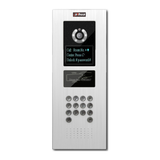
Control NO/NC of door lock. Access Control Output Port 1.2.2 VTO1210B(W)-X/VTO1220B(W) 1.2.2.1 Front Panel Plug to power, system boots up and wait for 1 minute, screen turns on. System enters working interface, see Figure 1- 3 VTO1210B(W)-X/VTO1220B(W). - Page 13 Figure 1- 3 VTO1210B(W)-X/VTO1220B(W) Please refer to the following sheet for detailed information. Name Function Logo Printed logo. Microphone Audio input It can compensate the camera light in Compensation Light the low illumination environments. Approaching It can detect approaching body. Induction Speaker Output audio...
- Page 14 Button. Backspace function. It is to delete the previous symbol. Hang up function. It is to hang up the call. 2. Number button. Input the number 0 to button. When you are using the Key Panel password to open the door. Press this button once to begin input.
- Page 15 1.2.2.2 Rear Panel Figure 1- 4 VTO1210B(W)-X/VTO1220B(W) rear structure Please refer to the following sheet for detailed information. SN Port Name Function Vandal Proof Alarm Button It can generate an alarm when there is a vandal operation. Network Port Connect to the RJ45 port. Connect to signal from the door sensor, door on/off signal.
-
Page 16: Vto1210C-X
Analog Signal Port Connect to the analog signal of the distributor. Connect to RS422 or RS484 communication device. RS485 Port 1.3 VTO1210C-X 1.3.1.1 Front Panel Plug to power, system boots up and wait for 1 minute, screen turns on. System enters working interface, see Figure 1- 5 VTO1210C-X. - Page 17 Figure 1- 5 VTO1210C-X Please refer to the following sheet for detailed information. Name Function Logo Printed logo. Microphone Audio input It can compensate the camera light in Compensation Light the low illumination environments. Speaker Output audio Button. Backspace function. It is to delete the previous symbol.
- Page 18 button. When you are using the password to open the door. Press this button once to begin input. After you input the password, please press it again to complete the operation. Call button. After you input the room number, press it to begin a dial up. Call center button.
- Page 19 please refer to Ch 1.2.2.2.
-
Page 20: Install Vto
2 Install VTO Unit VTO on-site installation includes: wall embedded installation, door embedded installation (with box/without box), standalone installation. This chapter will introduce installation VTO1220A/VTO1210A-X series, VTO1210B(W)-X/VTO1220B(W) series and VTO1210C-X series. 2.1 VTO1220A/VTO1210A-X 2.1.1 Screw Component Screw No Illustration Quantity ST3×18 Cross recessed pan head Screw a tapping screws –white alloy... -
Page 21: Wiring
Figure 2- 1 2.1.3 Wiring Please refer to Ch 1.2.1.2. 2.2 VTO1210B(W)-X/VTO1220B(W) 2.2.1 Screw Component Screw No Illustration Quantity ST3×18 Cross recessed pan head Screw a tapping screws –white alloy M3×16 Cross slot recessed pan head Screw b screws- zinc black... -
Page 22: Installation Steps
2.2.2 Installation Steps Step 1. Embed plastic housing into wall. Step 2. Fix bracket on the housing with screw a. Step 3. Fix device on the bracket with screw b. Figure 2- 2 2.2.3 Wiring Please refer to Ch 1.2.2.2. -
Page 23: Vto1210C-X
2.3 VTO1210C-X 2.3.1 Screw Component Illustration Quantity M4×40 inner hex flower countersunk flat head screws-stainless steel 2.3.2 Installation Steps Step 1. Embed plastic housing into wall. Step 2. Fix device on the bracket with screw. Figure 2- 3 2.3.3 Wiring Please refer to Ch 1.2.3.2. -
Page 24: Debug Vto
3 Debug VTO The VTO has digital system and analog system. Please read the following contents before installing system. Here takes VTO1220A as an example. 3.1 Digital System 3.1.1 System See Figure 3- 1 Digital system. Figure 3- 1 Digital system Note: VTO port (dual port VTO refers to Figure 1-4 no. -
Page 25: Configure Vto
3.1.2 Configure VTO Configure VTO info, make sure there is communication among center, VTO and VTH. Note: Access VTO WEB config interface via PC, and please make sure PC and VTO both connect to the Internet and are in the same segment. Step 1. - Page 26 Figure 3- 3 Step 4. Add digital VTH. In page, select System Config>VTH Management>Indoor Management. Click on Add to add VTH. Click on OK. See Figure 3- 4. Figure 3- 4 Note: If you want to add many room no., you can modify unit floor and rooms on a floor in Step 2 to batch add room no.
-
Page 27: Digital Vth
Figure 3- 5 3.1.3 Digital VTH Enters digital VTH system settings-project setting, input VTH project password 002236. According to VTO config, input room no.; in network config, set VTH IP, subnet mask, gateway and etc; in network terminal, fill in VTO IP, enable and click on OK. Note: Please refer to corresponding VTH user’s manual. -
Page 28: Configure Vto
Figure 3- 6 Analog System Note: VTO analog signal port (see Figure 1-2 and 1-4) connects to allocator IN port. Select any port of allocator to connect to VTH which allows allocator to power supply VTH. A-X connects to analog signal port network cable according to cable color, from down to up are: white-blue, blue, NA, NA, white-green, green, white-brown, and brown. - Page 29 Figure 3- 7 Step 3. Set LAN. In page, select System Config>LAN Config, enter LAN Config interface. The default config can ensure VTO and VTH are connected. If you want to configure center, the setup shall match setup in center and check register to the MGT center in LAN Config.
-
Page 30: Analog Vth
Step 2 to batch add room no. Parameter with * are mandatory. Step 5. Set network info. In page, select System Config>Network Config. Set VTO IP address, subnet mask and default gateway. After you are dome, WEB page will reboot and go to the new set page. See Figure 3- 9. Figure 3- 9 Note: Please refer to Ch 5. - Page 31 3.2.4 On VTH, press monitor button to monitor VTH video. On VTO, press room no. + to call correspinding VTH.
-
Page 32: Basic Functions
4 Basic Functions 4.1 Call Under standby status (Figure 1-1, Figure 1-2), press button, this VTO will call center. The video door phone begins when the port picks up. During the whole process, you can press the button to end current talk and return to the standby interface. -
Page 33: Modify Volume Config
4.2.3 Modify Volume Config In volume interface, adjust volume via button 4 and 6. When you finish, press to exit modification interface. 4.3 Issue Card In card issuing interface, select to issue card with parent card or password via button 2 and 8. -
Page 34: Unlock Via Ic Card
Self password: n standby interface, press , input 4-digit room no. + default password: 123456, press to unlock. For example, to unlock room 101, you shall input: #0101123456#. Defualt password can be changed in A&C Manager interface. 4.4.3 Unlock via IC card The door is open after you swipe IC card and the card passed the authentication and station verification. -
Page 35: Web Function
5 Web Function 5.1 Login In Internet Explorer, input VTO IP address as in Figure 5- 1. Figure 5- 1 You must input username and password in order to login WEB main interface. Default username: admin Default password: admin. After you login, you will see 4 major settings: system, info search, status statistics, and Logout. -
Page 36: Local Config
5.2.1 Local Config 5.2.1.1 Local Config In page, select System Config>Local Config. Set parameter, and click on OK. See Figure 5- 2. Figure 5- 2 Parameter Note Device Type Display device type. Video Format Set collected video format by camera, including:WVGA, D1. WVGA resolution si 800×480;D1 resolution is 704×576. - Page 37 Menace Password Set menace password. Default is 654321. Default Config Set all parameters to default status. Note: Every half an hour, VTO will automatically saves card no. and VTH info on VTO. 5.2.1.2 Config Manager In page, select System Config>Local Config>Config Manager. See Figure 5- 3. Figure 5- 3 Paraemter Note...
-
Page 38: Lan Config
Figure 5- 4 5.2.2 LAN Config In page, select System Config>LAN Config. Default setting is enough if you just want networking between VTO and VTH, but if you want to set the center, you need to change default settings to be identical with center info. You also need to check box register to MGT center. - Page 39 manager. VTO1220A only has digital indoor station manager. 5.2.3.1 Add Digital/Analog VTH Step 1. In page, select System Config>Indoor Manager>Digital Indoor Station (or Analog Indoor Station. Step 2. Click on Add. Step 3. Fill in VTH information, click on OK. See Figure 5- 6 for example as digital VTH.
-
Page 40: Allocator Manager
Allocator Allocator corresponding ports Port no. 4-ch allocator port is 1~4, 8-ch allocator port is 1~8. 5.2.3.2 Modify Digital/Analog VTH Click on , in pop-up page, modify VTH information. For digital VTH, you can only modify name information. For analog VTH, you can only modify name, allocator address and port. 5.2.3.3 Delete Digital/Analog VTH Click on to delete digital/analog VTH. -
Page 41: Video Set
5.2.6 Video Set In page, select System Config>Video Set. When you see ―w_no_plugins‖ on screen, please click on it and install control unit according to introduction. See Figure 5- 8. Figure 5- 8 Parameter Note Motion Detection When detect body approaching VTO, it will automatically turn on indicator. -
Page 42: Change Password
5.2.7 Change Password In page, select System Config>Change Password. In Change Password interface, you can change WEB login password of VTO. You must input old password, new password and confirm new password. Click on OK button to save. 5.2.8 User Manage Only when you login as admin, you can add, modify, delete and view user information. -
Page 43: Ipc Information
5.2.8.3 Delete User In User Manage interface, click on to delete user. 5.2.9 IPC Information In page, select System Config>IPC Information. You can view IPC video via the VTH. In IPC Information interface, click on , system pops up a box, fill in IPC information. See Figure 5- 10. -
Page 44: Info Search
Figure 5- 11 5.2.10.2 History Info In page, select System Config>Publish Information>History Info. You can view historical information, click on to delete ifnormation. 5.3 Info Search You can view call record, alarm record and swiping card record. 5.3.1 Call Record In page, select Info Search>Call History. -
Page 45: Alarm Record
5.3.2 Alarm Record In page, select Info Search>Alarm Record. You can search VTO alarm records and the system can store up to 1124 records. Click on Export Record to save record to local. See Figure 5- 13. Figure 5- 13 5.3.3 Swiping Card Record In page, select Info Search>Swiping Card Record. -
Page 46: Status Statistics
5.4 Status Statistics In page, select Status Statistics>VTH Status. You can view connection status of VTH. See Figure 5- 15. Figure 5- 15 5.5 Logout Click on Logout. Here you may select either to Reboot Device or Logout system. See Figure 5- 16 and Figure 5- 17. -
Page 47: Appendix 1 Specifications
Appendix 1 Specifications Model VTO1220A VTO1220B(W) VTO1210A-X VTO1210B(W)-X VTO1210C-X Main Processor Embedded micro processor Embedded LINUX OS Video Video Compression Standard H.264 Input/Approaching Induction 1.3 megapixel CMOS camera Back Light Support Auto Light Compensation Support Audio Input Microphone Output Built-in speaker Bidirectional Talk Support dual-way bidirectional talk Display... - Page 48 Power DC 12V Standby≤1W ;work≤10W Power Consumption -40℃~+60℃ Working Environments 10~95%RH VTO1212B(W)-X/VTO1220B Water proof level:IP65; Water Proof VTO1210A-X/VTO1210C-X Water proof level: IP53...
- Page 49 Note: This manual is for reference only. Slight difference may be found in user interface. All the designs and software here are subject to change without prior written notice. All trademarks and registered trademarks are the properties of their respective owners.
Need help?
Do you have a question about the VTO12 Series and is the answer not in the manual?
Questions and answers