Table of Contents
Advertisement
Advertisement
Table of Contents

Related Manuals for Dahua VTO5110B


Summary of Contents for Dahua VTO5110B
- Page 1 Villa Door Station User’s Manual For VTO5000 Series V1.0.0...
-
Page 2: Table Of Contents
Table of Contents Product Appearance ..................2 Front Panel ..................... 2 Port ......................... 4 Installation Guide ..................0 Basic Function Introduction ................0 Call User ......................0 3.1.1 Connect ....................0 3.1.2 Call ....................... 0 Monitor ......................0 Issue Card/Delete Card ................... 0 3.3.1 Issue Card .................... -
Page 3: Product Appearance
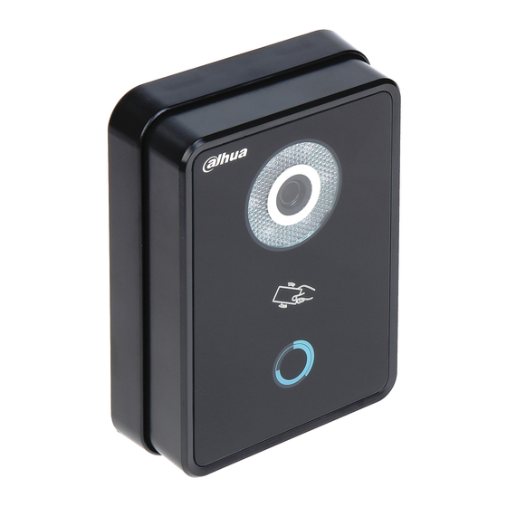
1 Product Appearance 1.1 Front Panel The product appearances of VTO5110B and VTO5110BW are shown in Figure 1- 1 VTO5110B and Figure 1- 2 VTO5110BW. Figure 1- 1 VTO5110B... - Page 4 Figure 1- 2 VTO5110BW Name Function LED compensation will automatically turn on during monitoring, connecting, Compensation call and alarm statuses if there is no enough light in environment. Camera It monitors corresponding door area. Card Reading Area You can swipe card in this area. You can touch this button to call multiple Touch Button VTHs at the same time.
-
Page 5: Port
It monitors corresponding door area. You can touch this button to call multiple Touch Button VTHs at the same time. 1.2 Port Port of VTO5110B/BW is shown in Figure 1- 4. Port of VTO5x00Cx series is shown in Figure 1- 5 VTO5x00Cx Series. - Page 6 Figure 1- 4 VTO5110B/BW Port Name Function Network port Connect to analog VTH. Network port Connect to analog VTH. Power port Connect to 24V DC power Lock port Connect to lock, unlock button...
- Page 7 Figure 1- 5 VTO5x00Cx Series Port Name Function Network port 1 Connect to analog VTH. Network port 2 Connect to analog VTH. Power port Connect to 24V DC power Debugging port For installation staff use Green port 1 Connect to lock Green port 2 Connect to door sensor and unlock button.
-
Page 8: Installation Guide
86 box onto wall after locking the 86 box. (as c in Figure 2- 1 VTO5110B/BW); Install 1 in Figure 2- 1 VTO5110B/BW onto the holder. Fasten edge and lightly push its bottom edge. After you complete the installation between VTO and holder, use the set screw... - Page 9 Figure 2- 2 VTO5x00Cx Series Installation step: Fix installation holder onto wall: Use the M4 screw accompanied with the VTO to fix holder onto the 86 box (as 3 in Figure 2- 2 VTO5x00Cx Series); B in Figure 2- 2 VTO5x00Cx Series is to strengthen firmness of VTO, use the ST3.0 screw accompanied with VTO to fix the 86 box onto wall after locking the 86 box.
-
Page 10: Basic Function Introduction
3 Basic Function Introduction 3.1 Call User 3.1.1 Connect VTO is connected to VTH via network connection. At VTO, You can touch the button to call all VTHs of designated user. During connecting, you can touch the button on VTO to end call at any time. -
Page 11: Unlock
3.4 Unlock 3.4.1 Unlock Interval In VTH menu, set unlock interval, max 25s. 3.4.2 Unlock under Connecting Status Under connecting status, VTH can remotely unlock door. VTO will return to standby interface after call ends or countdown stops. 3.4.3 2.4.2 Unlock under Calling Status Under calling status, VTH can remotely unlock door. -
Page 12: Door Unlocked Overtime Alarm
3.7 2.7 Door Unlocked Overtime Alarm When door has been opened for more than 120s, VTO will generate alarm and meanwhile the alarm plus video will be reported to VTH. -
Page 13: Faq
Q: How do I know if the power supply to VTO is working normally? A: For VTO5110B and VTO5110BW, when you plug the device to power supply, wait about 1s and press the touch button to turn on back light. For VTO5000C and VTO5000CM, when you plug the device to power supply, wait about 1s, you shall see blue indicators around touch button turn on. -
Page 14: Appendix 1 Technical Specifications
Appendix 1 Technical Specifications Model VTO5110B/ VTO5110BW Video Type Color Resolution 600 line Night vision Support Audio Input Omnidirectional microphone Output Built-in speaker Bidirectional talk Support Operation Mode Input Single-button input (with back light) Swipe card Built-in IC card sensor... - Page 15 Power DC 24V Power Standby≤1W ;working≤4W consumption Environment -30℃~60℃ Dimensions 141*100*17mm (L*W*H) Note: This manual is for reference only. Slight difference may be found in user interface. All the designs and software here are subject to change without prior written notice.
Need help?
Do you have a question about the VTO5110B and is the answer not in the manual?
Questions and answers