Table of Contents
Advertisement
Quick Links
Advertisement
Table of Contents

Related Manuals for Tysso AP-3515


Summary of Contents for Tysso AP-3515
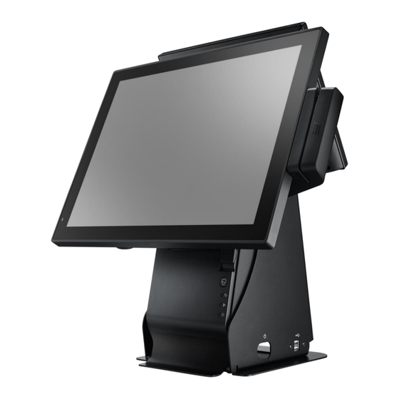
- Page 1 AP-3515 15 Inches All-in-One POS System Service Manual...
-
Page 2: Table Of Contents
Contents Before Using the Product Revision History Read This First Safety Information Information on Copyrights System Disassembly Before You Start Detach the Optional Peripherals Unplug the cables from the POS unit Remove the optional i-Button unit Disconnect the MSR modular unit Disconnect the Modular VFD Customer Display Remove the Printer from the Base Unit Detach the Base from the POS Unit... - Page 3 Remove the Speaker Replace the Main Power LED Indicator Disconnect the LVDS and Inverter Cables from the LCD Panel Set Disassemble the LCD Panel Set Application Programs Installing the Printer Specifications Main Board Layout Exploded View Parts Description Main Board and Parts Copyright ©...
-
Page 4: Before Using The Product
Before Using the Product Revision History Date Version Update Summary Remark Approved By 2019/11/04 V1.0 Initial Release Joyce Huang Robert Kuo Copyright © 2019 Fametech Inc. All Rights Reserved. All other brands, product names, company names, trade names, trademarks and service marks used herein are the property of their respective owners. -
Page 5: Read This First
The basic drivers and utilities that come with your system are subject to change. • TYSSO assumes no responsibility for damages resulting from a use of the product that is not approved by TYSSO, or failure to follow the precautions and instructions provided in this Service Manual. - Page 6 • Do not modify or extend the power cable. Cable damage may cause an electrical shock or fire. • Do not use a damaged power cord or plug, or a loose outlet. These may cause a fire, short circuit, or electrical shock. •...
-
Page 7: Information On Copyrights
All product names used in this manual are the properties of their respective owners and are acknowledged. About This Manual The service manual provides service information for the AP-3515. This manual is designed to help train service personnel to locate and fix failing parts on the machine. Copyright © 2019 Fametech Inc. All Rights Reserved. - Page 8 This manual consists of the following sections: Before Using the Product System Disassembly Application Programs Specifications FCC Statement This device has been tested and found to comply with the limits for a Class A digital device, pursuant to part 15 of the FCC Rules, these limits are designed to provide reasonable protection against harmful interference when the device is operated in a commercial environment.
- Page 9 Vermont Mercury Management Rules LCD display lamps contain mercury. Dispose of them properly. CE Mark The above equipment was tested for compliance with the requirements set forth in the EUROPEAN COUNCIL Directive 2014/30/EU and the technical standards mentioned above. The results of testing in this report apply only to the product/system, which was tested. Other similar equipment will not necessarily produce the same results due to production tolerance.
- Page 10 To prevent possible harm to the environment or human health from uncontrolled waste disposal, please separate this device from other types of waste and recycle it responsibly to promote the sustainable reuse of material resources. Business users should contact their supplier and check the terms and conditions of the purchase contract regarding its disposal.
-
Page 11: System Disassembly
• There are no serviceable parts or components in AP-3515 or peripherals. DO NOT modify any parts of AP-3515 or use non-qualified parts or peripherals. • Store the disconnected parts, cables, devices and screws in a secure location for further use. -
Page 12: Detach The Optional Peripherals
Detach the Optional Peripherals There are some of the optional peripherals installed onto the POS system. Please detach the peripherals and store them in a secure location. Note: • Please turn off the whole POS system and unplug the power cables from the electrical outlet. -
Page 13: Remove The Optional I-Button Unit
Remove the optional i-Button unit ①. Turn the POS counter clock-wise with the rear facing toward the operator. ②. Use a screw driver to loosen the securing screw. ③. Detach the i-Button from the POS terminal. Note: • Store the detached i-Button and screw in a secure location for further use. Copyright ©... -
Page 14: Disconnect The Msr Modular Unit
Disconnect the MSR modular unit ①. Turn the POS clockwise with the rear facing toward the operator. ②. Use a screw driver to loosen the securing screw. ③. Detach the MSR module from the POS terminal. Note: • Store the detached MSR unit and screw in a secure location for further use. Copyright ©... -
Page 15: Disconnect The Modular Vfd Customer Display
Disconnect the Modular VFD Customer Display ①. Lay the POS terminal face down on the surface*. Note: • To prevent the LCD panel from injuries, carefully lay the front of the POS face down on a flat, clean, and stable surface with additional cushioned material (for example: a blanket). - Page 16 ④. Disconnect the flat ribbon cable of Customer Display from the POS unit. Note: • Optional top I/O cover of VFD customer display If the VFD customer display is removed and no longer be used, please install a VFD top I/O cover to prevent the POS unit from dust, object or liquid.
-
Page 17: Remove The Printer From The Base Unit
Remove the Printer from the Base Unit ①. Loosen two securing screws on the cover and remove the cover. ②. Detach two cables on the printer (USB & power cable) and remove the printer. USB cable Power cable Copyright © 2019 Fametech Inc. All Rights Reserved. All other brands, product names, company names, trade names, trademarks and service marks used herein are the property of their respective owners. -
Page 18: Detach The Base From The Pos Unit
Detach the Base from the POS Unit ①. Lay the POS terminal face down on the surface. Note: • To prevent the LCD panel from injuries, carefully lay the front of the POS face down on a flat, clean, and stable surface with additional cushioned material (for example: a blanket). - Page 19 ③. Loosen two securing screws near two sides of the base. ④. Detach the base from the POS unit. ⑤. Loosen two securing screws (orange mark) and remove two USB connectors (red mark). Copyright © 2019 Fametech Inc. All Rights Reserved. All other brands, product names, company names, trade names, trademarks and service marks used herein are the property of their respective owners.
-
Page 20: Remove The Hdd/Ssd Drive From The Pos Unit
Remove the HDD/SSD Drive from the POS Unit ①. Lay the POS unit down on the surface*. Note: • To prevent the LCD panel from injuries, carefully put the front of the POS face down on a flat, clean, and stable surface with additional cushioned material (for example: a blanket). - Page 21 TIP: Replace the HDD/SSD Drive To replace the HDD/SSD drive: Remove the securing screws of HDD/SSD module (in the LEFT/RIGHT side). Replace a new HDD or SSD drive and re-install to the HDD bracket. DATA POWER Connect Connect Securing Screw Hole When Disassembling: ...
-
Page 22: Disassemble The Pos Unit
Disassemble the POS Unit Remove the back cover of the POS unit ①. Loosen and remove the securing screws from the POS unit (as red marks indicated). ②. Remove the back cover of the POS unit. Note: • Please use only the supplied screws on the correct securing holes. •... -
Page 23: Remove The Metal Hdd Slot
Remove the Metal HDD Slot ①. Use a screw to remove the securing screws of HDD Connector on the HDD slot. ②. Remove the securing screws on the bottom I/O port. Power DATA Connect Connect ③. Remove the metal HDD slot from the POS unit. Copyright ©... -
Page 24: Remove The Top I/O Board (Of Modular Vfd Customer Display)
Remove the Top I/O Board (of Modular VFD Customer Display) ①. Disconnect the cable of top I/O board (yellow mark) from the main board (COM 5). ②. Remove the securing screws of top I/O board. Note: • Store the top I/O board and screws in a secure location for further use. Copyright ©... -
Page 25: Disconnect The Hdd Cable
Disconnect the HDD Cable ①. Disconnect the HDD cable. (power and data connector). Data Connector Power Connector Note: There is a cable binder on the cables of HDD and MSR slot board. Cut the cable binder before disconnect the HDD cable. ... -
Page 26: Remove The Touch Control Board
Remove the Touch Control Board ①. Disconnect the cable from touch control board to main board (J_USB2). ②. Disconnect the flat tape cables of the touch panel. Copyright © 2019 Fametech Inc. All Rights Reserved. All other brands, product names, company names, trade names, trademarks and service marks used herein are the property of their respective owners. - Page 27 ③. Use a screw driver to remove two securing screws from the touch control board. Note: • Store the detached touch control board and screws in a secure location for further use. Copyright © 2019 Fametech Inc. All Rights Reserved. All other brands, product names, company names, trade names, trademarks and service marks used herein are the property of their respective owners.
-
Page 28: Remove The Msr Slot Board (J_Usb3 And Com4)
Remove the MSR Slot Board (J_USB3 and COM4) ①. Disconnect the connectors of MSR slot board from the main board. COM 4 J_USB 3 Copyright © 2019 Fametech Inc. All Rights Reserved. All other brands, product names, company names, trade names, trademarks and service marks used herein are the property of their respective owners. - Page 29 ②. Loosen the securing screws to remove the MSR slot board. Copyright © 2019 Fametech Inc. All Rights Reserved. All other brands, product names, company names, trade names, trademarks and service marks used herein are the property of their respective owners.
-
Page 30: Disconnect The Side Usb Board (Near Main Power Switch)
Disconnect the Side USB Board (near Main Power Switch) ①. Disconnect the cable on the USB port (J_USB1 of the main board). J_USB Copyright © 2019 Fametech Inc. All Rights Reserved. All other brands, product names, company names, trade names, trademarks and service marks used herein are the property of their respective owners. -
Page 31: Remove The Side Usb Board And Power Switch
Remove the Side USB Board and Power Switch ①. Disconnect the power switch cables (black & white) from the main board. PWS - PWS + ②. Use a screw driver to remove the side USB board. Copyright © 2019 Fametech Inc. All Rights Reserved. All other brands, product names, company names, trade names, trademarks and service marks used herein are the property of their respective owners. - Page 32 ③. Press two sides of the snap-type main power switch (as blue arrows indicated) and push the switch out of the bracket. Copyright © 2019 Fametech Inc. All Rights Reserved. All other brands, product names, company names, trade names, trademarks and service marks used herein are the property of their respective owners.
-
Page 33: Disconnect The Main Power Led Indicator From The Main Board
Disconnect the Main Power LED Indicator from the Main Board ①. Disconnect the connector of the main power LED indicator. ②. Disconnect the blue-white twisted pair cable from the main board. Copyright © 2019 Fametech Inc. All Rights Reserved. All other brands, product names, company names, trade names, trademarks and service marks used herein are the property of their respective owners. -
Page 34: Disconnect The Speaker (Audio) From The Main Board
10. Disconnect the Speaker (Audio) from the Main Board ①. Disconnect the Speaker (red-black twisted cable) from the main board. ②. Complete the following steps to remove the main board, then you can remove the speaker. Copyright © 2019 Fametech Inc. All Rights Reserved. All other brands, product names, company names, trade names, trademarks and service marks used herein are the property of their respective owners. -
Page 35: Disconnect The Inverter Cable And Lvds Cable From The Main Board
11. Disconnect the Inverter Cable and LVDS Cable from the Main Board ①. Disconnect the inverter cable (yellow mark) and LVDS cable (blue mark). Inverter Cable LVDS Cable Copyright © 2019 Fametech Inc. All Rights Reserved. All other brands, product names, company names, trade names, trademarks and service marks used herein are the property of their respective owners. -
Page 36: Remove The Bottom I/O Bracket
12. Remove the Bottom I/O Bracket ①. Use a HEX screw driver to remove the hex mounting screws on the bottom I/O bracket. ②. Remove all of the securing screws on the bottom I/O bracket. ③. Slightly push the bracket to remove it out of the POS unit. Note: ... -
Page 37: Remove The Main Board
13. Remove the Main Board ①. Use a screw driver to remove the securing screws on the main board (as yellow marks indicated). Note: • Store the detached main board, parts and screws in a secure location for further use. Copyright ©... -
Page 38: Remove The Ram Module
14. Remove the RAM Module ①. Release the latches on two sides of the RAM module slot. ②. Gently slide the Module out of the slot. Note: • Remove all of the RAM modules and store them in a secure location for further use. Copyright ©... -
Page 39: Cmos Battery Replacement
15. CMOS Battery Replacement If you notice that the system date and time often reset to the factory date (older date and time) and need to be adjusted when the POS terminal is powered off and on, the battery is probably starting to fail and should be replaced. - Page 40 Replacement: Remove the CMOS battery from the battery holder. Place the new battery into the holder, with the smooth, flat side of the battery on the top. Note: • Place the battery with correct polarity. Copyright © 2019 Fametech Inc. All Rights Reserved. All other brands, product names, company names, trade names, trademarks and service marks used herein are the property of their respective owners.
-
Page 41: Remove The Speaker
16. Remove the Speaker ①. Remove the black tape on the red-black twisted pair cable. ②. Loosen two securing screws and remove the speaker. Copyright © 2019 Fametech Inc. All Rights Reserved. All other brands, product names, company names, trade names, trademarks and service marks used herein are the property of their respective owners. -
Page 42: Replace The Main Power Led Indicator
17. Replace the Main Power LED Indicator The main power LED indicator is on the edge of the front bezel set and does not need to be removed from the bezel set. If the LED indicator is not functioning and needs to be replaced to a new one, please follow the instruction as below: ①. -
Page 43: Disconnect The Lvds And Inverter Cables From The Lcd Panel Set
18. Disconnect the LVDS and Inverter Cables from the LCD Panel Set LVDS Cable Inverter Cable ①. Disconnect the inverter cable and LVDS cable from the LCD panel set. Copyright © 2019 Fametech Inc. All Rights Reserved. All other brands, product names, company names, trade names, trademarks and service marks used herein are the property of their respective owners. -
Page 44: Disassemble The Lcd Panel Set
19. Disassemble the LCD Panel Set Use a screw driver to remove the securing screws of LCD panel set. There are two screws on both sides of the LCD panel and chassis. Loosen the screws and then remove the chassis from the LCD panel. Warning: The Front Bezel Set is pre-assembled in factory and NOT Detachable. -
Page 45: Application Programs
Application Programs Installing the Printer Connecting Your Printer Please check the printer and the supplied accessories before Installation. It’s recommended to read the entire instruction manual prior to the installation. ①. Place the printer on the designate location. ②. Plug the connector of power adaptor to the printer. ③. - Page 46 Control buttons & Indicator Power Indicator Error Indicator Paper Indicator Paper Feed Button Cover Release Button Control Buttons Paper Feed: This function is to advance the paper. Press the key and the paper advances by a single line. Press and hold the key for over 3 seconds and the paper advances by multiple lines. Cover Release Button: Pull to open the printer cover.
- Page 47 Installing the Driver of the Printer Before installing the driver of your printer, make sure the printer is properly connected to the host PC. To install the driver of the printer: ①. Access the website www.fametech.com.tw and download the driver. ②.
- Page 48 ④. Select the Operating System: For example: select “Windows 8 Windows 10” for Windows 10 version. Click “Install Printer Driver (N)” to continue. ⑤. Default Printer Setting: To set the printer as the default printer, click the checkbox “Set Default” to confirm. Click “Next”...
- Page 49 ⑥. Select the proper Port available (for USB). ⑦. The driver is successfully installed. Note: • Please refer to the instruction manual for further information. Copyright © 2019 Fametech Inc. All Rights Reserved. All other brands, product names, company names, trade names, trademarks and service marks used herein are the property of their respective owners.
-
Page 50: Specifications
Specifications Main Board Layout COM 4 COM 6 (to MSR Board) COM 5 Memory Slot (to VFD) Data Connector Power Connector Inverter LVDS Indicator J_USB3 (to MSR Board) Power Switch J_USB1 (Side USB Board) Speaker (Audio Connector) Copyright © 2019 Fametech Inc. All Rights Reserved. All other brands, product names, company names, trade names, trademarks and service marks used herein are the property of their respective owners. -
Page 51: Exploded View
Exploded View Copyright © 2019 Fametech Inc. All Rights Reserved. All other brands, product names, company names, trade names, trademarks and service marks used herein are the property of their respective owners. -
Page 52: Parts Description
Parts Description Item Front Bezel Set LED Indicator LCD Panel Panel Chassis Thermal Pad Heat Sink Thermal Pad Main Board Side USB Board Power Switch Power Switch Bracket VFD Slot Board Touch Control Board MSR Board MSR Slot Bracket Speaker Bottom I/O Bracket 17-a I/O Connector... -
Page 53: Main Board And Parts
Main Board and Parts Main Board Connection/Installation Notes The table below is the descriptions of the connectors of the main board. Each connector/slot is used for the specified part or optional peripheral. Please refer to the notes as below and examine the layouts of the main boards to locate the connectors so as to complete the installation.
Need help?
Do you have a question about the AP-3515 and is the answer not in the manual?
Questions and answers