Table of Contents
Advertisement
Available languages
Available languages
istruzioni originali/original instructions
ISTRUZIONI PER L'INSTALLAZIONE E L'USO
IT
INSTALLATION AND USE INSTRUCTIONS
EN
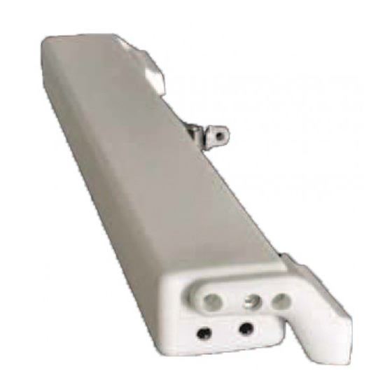
ATTUATORE A CATENA PER AUTOMAZIONE FINESTRE
C15
CHAIN ACTUATOR FOR WINDOW AUTOMATION
+
-
BREVETTATO-PATENTED
COD. 0P5040
VER.0.0
REV.02.18
PRIMA DI INSTALLARE E UTILIZZARE L'ATTUATORE È OBBLIGATORIO CHE L'INSTALLATORE E L'UTILIZZATORE LEGGANO
E COMPRENDANO IN TUTTE LE SUE PARTI IL PRESENTE MANUALE.
BEFORE INSTALLING AND USING THE ACTUATOR, IT IS COMPULSORY FOR THE INSTALLER AND THE USER TO READ AND
UNDERSTAND THIS MANUAL IN ALL ITS PARTS.
IL PRESENTE MANUALE È PARTE INTEGRANTE DELL'ATTUATORE E DEVE OBBLIGATORIAMENTE ESSERE CONSERVATO
PER FUTURI RIFERIMENTI FINO ALLA DEMOLIZIONE DELLO STESSO.
THIS MANUAL IS INTEGRAL PART OF THE ACTUATOR AND MUST BE PRESERVED FOR FUTURE REFERENCE UNTIL
DEMOLITION OF THE SAME.
Advertisement
Chapters
Table of Contents

Subscribe to Our Youtube Channel
Related Manuals for TOPP C15 Series


Summary of Contents for TOPP C15 Series
- Page 1 istruzioni originali/original instructions ISTRUZIONI PER L’INSTALLAZIONE E L’USO INSTALLATION AND USE INSTRUCTIONS ATTUATORE A CATENA PER AUTOMAZIONE FINESTRE CHAIN ACTUATOR FOR WINDOW AUTOMATION BREVETTATO-PATENTED COD. 0P5040 VER.0.0 REV.02.18 PRIMA DI INSTALLARE E UTILIZZARE L’ATTUATORE È OBBLIGATORIO CHE L’INSTALLATORE E L’UTILIZZATORE LEGGANO E COMPRENDANO IN TUTTE LE SUE PARTI IL PRESENTE MANUALE.
-
Page 2: Table Of Contents
INDICE 1- DICHIARAZIONE CE DI INCORPORAZIONE DI QUASI MACCHINA ..pag. 03 2- GENERALITÀ 2.1- Avvertenze generali..................pag. 04 2.2- Installatore e utilizzatore...................pag. 04 2.3- Assistenza tecnica....................pag. 04 2.4- Descrizione del personale ................pag. 04 3- DESCRIZIONE TECNICA 3.1- Targa dati e marcatura “CE”................pag. 04 3.2- Denominazione dei componenti e dimensioni..........pag. -
Page 3: 1- Dichiarazione Ce Di Incorporazione Di Quasi Macchina
36066 Sandrigo (VI) Italia dichiara che la persona autorizzata a costituire il fascicolo tecnico è Nome: Bettiati Roberto - Topp S.r.l. Indirizzo: via Galvani,59 36066 Sandrigo (VI) e che alla seguente quasi macchina ATTUATORE A CATENA PER AUTOMAZIONE FINESTRE Tipo:... -
Page 4: Avvertenze Generali
GENERALITÀ installazione. AVVERTENZE GENERALI L'installatore sarà l'unico soggetto responsabile per & l'errata installazione e per il mancato rispetto delle Prima di installare e utilizzare l’attuatore è istruzioni riportate nel presente manuale. L'installatore obbligatorio che l’installatore e l’utilizzatore risponderà pertanto in via esclusiva nei confronti leggano e comprendano in tutte le sue parti il dell'utente e/o di terzi per tutti i danni a cose e/o persone presente manuale. -
Page 5: Dati Tecnici
DATI TECNICI Nella Tab. 1 vengono riportati i dati tecnici che caratterizzano Tab.1 l’attuatore. C15/230V C15/24V 230 V ~ 50 Hz 24 V Tensione d’alimentazione Assorbimento 0,43 A 0,12 A Potenza assorbita a carico 25 W Forza di spinta 300 N Forza di trazione 200 N 7,5 mm/s... -
Page 6: Confezione
& È assolutamente vietato l’impiego e l’utilizzo CONFEZIONE dell’attuatore per usi impropri, diversi da quello Ogni confezione del prodotto (scatola in cartone) previsto dal fabbricante (v. par.3.4). contiene (Fig.3): & È assolutamente vietato installare l’attuatore sulla parte esterna del serramento soggetto agli agenti •N.1 Attuatore completo di cavo di alimentazione elettrica;... -
Page 7: Rischi Residui
volontaria scorretta. RISCHI RESIDUI Dimensione del danno: Lesioni leggere (normalmente Si informano l’installatore e l'utilizzatore che dopo reversibili). l’installazione dell’attuatore sul serramento, l’azionamento Provvedimenti adottati: Obbligo, prima dell’avviamento, dello stesso può accidentalmente generare il seguente di accertarsi che nelle vicinanze del serramento non vi rischio residuo: siano persone, animali o cose la cui incolumità... -
Page 8: Collegamento Elettrico
Conclusa la fase di chiusura, 2) UNITÀ DI COMANDO E ALIMENTAZIONE: verificare che il serramento sia completamente chiuso Centrali a microprocessore TOPP serie TF che controllando lo schiacciamento delle guarnizioni; comandano il singolo attuatore o simultaneamente più... -
Page 9: Manovre Di Emergenza
Tale attività di manutenzione potrà essere persone non autorizzate. svolta o da TOPP, in forza di uno specifico accordo Il progetto dell’attuatore prevede l’utilizzo di componenti raggiunto con l'utente, o dall'installatore o da altro che non richiedono manutenzione periodica o personale tecnico, competente e qualificato nonché... - Page 10 INDEX 1- EC DECLARATION OF INCORPORATION OF PARTLY COMPLETED MACHINERY ......................page 11 2- GENERAL REMARKS 2.1- General instructions..................page 12 2.2- Installer and user ....................page 12 2.3- Technical assistance..................page 12 2.4- Description of personnel...................page 12 3- TECHNICAL DESCRIPTION 3.1- Rating plate and “CE” marking.................page 12 3.2- Denomination of the components and dimensions ..........page 12 3.3- Technical data....................page 13 3.4- Destination of use.....................page 13...
-
Page 11: Machinery
36066 Sandrigo (VI) Italia herewith declares that the person authorised to compile the technical file is Name: Bettiati Roberto - Topp S.r.l. Address: via Galvani,59 36066 Sandrigo (VI) and that to the partly completed machinery CHAIN ACTUATOR FOR WINDOW AUTOMATION... -
Page 12: 2- General Remarks
GENERAL REMARKS of installation. GENERAL INSTRUCTIONS The installation technician shall accept full & Before installing and using the actuator, it is responsibility for any installation errors and for any failure compulsory that the installer and the user to adhere to the instructions provided in this manual. The carefully read and understand this manual in all installation technician shall therefore be exclusively its parts. -
Page 13: Technical Data
TECHNICAL DATA Tab. 1 contains the technical data characterising the actuators. Tab.1 C15/230V C15/24V 230 V ~ 50 Hz 24 V Power supply voltage Absorbed current 0,43 A 0,12 A Absorbed power with load 25 W Thrust force 300 N Tractive force 200 N 7,5 mm/s... -
Page 14: Package
It is strictly forbidden to use the actuator for & PACKAGE improper uses other than the one foreseen bythe manufacturer (see par. 3.4). Each package of the product (cardboard box) contains It is strictly forbidden to install the actuator on the &... -
Page 15: Residual Risks
RESIDUAL RISKS The installer and the user are herewith informed that after or the user decides to perform a wrong voluntary action. the actuator has been installed on the window, the Severity of the damage: Light lesions (usually actuator drive can accidentally generate the following reversible). -
Page 16: Electrical Connections
6) Fig. 17- Using the supplied screws “V4”, mount the CONTROL DEVICES bracket “S2” on the movable part of the window frame using the references marked on the template; The control devices used to drive the actuator must & 7) Fig. 14- (Ref. 2) Screw a screw “V3” into the suitable assure the safety conditions foreseen by the laws in hole on one side of the actuator. -
Page 17: 6- Use And Operation
TOPP, of the actuator may only be performed after in accordance with a specific agreement made with the user, disconnecting it from the power supply. -
Page 18: 10- Figure
FIGURE/FIGURES Fig. 2 Dimensioni in mm/Dimensions in mm 15.1 64.5 LEGENDA: LEGENDA: 1) Cavo di alimentazione elettrica 1) Power supply cable 2) Testate supporto 2) Support heads 3) Attuatore 3) Actuator 4) Staffa per apertura a “vasistas” 4) Bracket for bottom hung opening 5) Terminale catena 5) Chain end 6) Staffa di attacco al serramento... - Page 19 FIGURE/FIGURES Fig.3 Fig.4 MACCHINA AD AVVIAMENTO AUTOMATICO AUTOMATIC MACHINE PRIMA DI INSTALLARE E UTILIZZARE L'ATTUATORE È OBBLIGATORIO CHE L'INSTALLATORE E L'UTILIZZATORE LEGGANO E COMPRENDANO IN TUTTE LE SUE PARTI IL MANUALE THE INSTALLER AND USER MUST READ AND UNDERSTAND ALL PARTS OF THIS MANUAL BEFORE INSTALLING AND USING THE ACTUATOR.
- Page 20 FIGURE/FIGURES Fig. 9 Fig. 10 Fig. 12 Fig. 11 Fig. 13 Fig. 14 FIGURE/FIGURES...
- Page 21 FIGURE/FIGURES Fig. 16 Fig. 15 Fig. 17 Fig. 18 Fig. 19 FIGURE/FIGURES...
- Page 22 FIGURE/FIGURES 24 V Schema elettrico/Wiring diagram ATTUATORE TOPP / TOPP ACTUATOR 24V CC (min. 21V - max. 28V) C15/24 C15/24 CHIUDE/CLOSES BLU/BLUE (NERO/BLACK) MARRONE/BROWN (ROSSO/RED) APRE/OPENS Schema elettrico/Wiring diagram 230 V ATTUATORE TOPP / TOPP ACTUATOR C15/230 C15/230 230V~50Hz CHIUDE/CLOSES...
- Page 24 TOPP S.r.l. Società a Socio Unico soggetta a direzione e coordinamento di 2 Plus 3 Holding S.p.a. Via Galvani, 59 - 36066 Sandrigo (VI) - Italia Tel. +39 0444 656700 - Fax +39 0444 656701 Info@topp.it - www.topp.it...
Need help?
Do you have a question about the C15 Series and is the answer not in the manual?
Questions and answers