Table of Contents
Advertisement
Quick Links
INSTALLATION AND USE INSTRUCTIONS
CHAIN ACTUATOR FOR
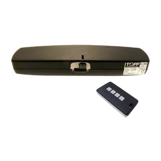
C30
WINDOW AUTOMATION
PATENTED
P/N 0P5201
VER.1.0
REV.07.04
BEFORE INSTALLING AND USING THE ACTUATOR, IT IS
COMPULSORY FOR THE INSTALLER AND THE USER TO READ
AND UNDERSTAND THIS MANUAL IN ALL ITS PARTS.
THIS MANUAL IS INTEGRAL PART OF THE ACTUATOR
AND MUST BE PRESERVED FOR FUTURE REFERENCE
UNTIL DEMOLITION OF THE SAME.
Advertisement
Table of Contents

Related Manuals for TOPP C30


Summary of Contents for TOPP C30
- Page 1 INSTALLATION AND USE INSTRUCTIONS CHAIN ACTUATOR FOR WINDOW AUTOMATION PATENTED P/N 0P5201 VER.1.0 REV.07.04 BEFORE INSTALLING AND USING THE ACTUATOR, IT IS COMPULSORY FOR THE INSTALLER AND THE USER TO READ AND UNDERSTAND THIS MANUAL IN ALL ITS PARTS. THIS MANUAL IS INTEGRAL PART OF THE ACTUATOR AND MUST BE PRESERVED FOR FUTURE REFERENCE UNTIL DEMOLITION OF THE SAME.
-
Page 3: Table Of Contents
INDEX 1- DECLARATION OF "CE" CONFORMITY ........................page 04 2- GENERAL REMARKS 2.1- General instructions................page 05 2.2- Installer and user ................page 05 2.3- Warranty ....................page 05 2.4- Technical assistance ................page 05 2.5- Reserved rights .................page 05 3- TECHNICAL DESCRIPTION 3.1- Rating plate and "CE" marking ............page 06 3.2- Denomination of the components and dimensions......page 07 3.3- Technical data..................page 08... -
Page 4: 1- Declaration Of "Ce" Conformity
1- DECLARATION OF "CE" CONFORMITY TOPP SPA - Via Galvani, 59 36066 SANDRIGO (VI) - ITALIA Tel. +39 0444 656700 Fax +39 0444 656701 Declares that the electric device Called: ATTUATORE PER AUTOMAZIONE FINESTRE Type: C30 Models: C30/230V - C30/24V Serial No.: see data plate and CE marking applied on the equipment... -
Page 5: General Instructions
GENERAL REMARKS -2 2.1- GENERAL INSTRUCTIONS BEFORE INSTALLING AND USING THE ACTUATOR, IT IS COMPULSORY THAT THE INSTALLER AND THE USER CAREFULL Y READ AND UNDERSTAND THIS MANUAL IN ALL ITS PARTS. THIS MANUAL IS INTEGRAL PART OF THE ACTUATOR AND MUST COMPULSORILY BE PRESERVED FOR FUTURE REFERENCE. -
Page 6: 3- Technical Description
3- TECHNICAL DESCRIPTION 3.1- RATING PLATE AND "CE" MARKING The "CE" marking certifies the compliance of the machine with the essential safety and health requirements foreseen by the product European Directives. The rating plate is an adhesive plate in polyester, silk-screen printed in black, having the following size: L=36 mm - H=50 mm. -
Page 7: Denomination Of The Components And Dimensions
TECHNICAL DESCRIPTION -3 3.2- DENOMINATION OF THE COMPONENTS AND DIMENSIONS Fig.2 Dimensions in mm LEGEND: 1) Semi-automatic coupling 2) Slot side indicator 3) Bracket for bottom hung opening 4) Opening stroke adjustment switch I=200 mm; II=380 mm 5) Connection bracket to the frame 6) Actuator 7) Chain adjustment end 8) Chain end adjustment screw... -
Page 8: Technical Data
3- TECHNICAL DESCRIPTION 3.3- TECHNICAL DATA Tab.1 contains the technical data characterising the actuators. C30/230V C30/24V Power supply voltage 230 V 50 Hz 24 V DC 0,22 A 1,3 A Absorbed current Absorbed power with load 50 W 35 W... -
Page 9: Destination Of Use
TECHNICAL DESCRIPTION -3 3.4- FORMULAS FOR THE CALCULATION OF THRUST AND TRACTIVE FORCE Fig.3 Horizontal domes or skylights F= Force necessary for opening or closing P= Weight of the skylight or dome (Only movable part) F = 0,54 x P Fig.4 Top hung windows (A) or bottom hung windows (B) -
Page 10: Use Limits
3- TECHNICAL DESCRIPTION 3.6- USE LIMITS The actuator has been designed and manufactured exclusively for the destination of use given in par.3.5, therefore, any other type of use is strictly forbidden in order to assure in any moment the safety of the installer and of the user, as well as the efficiency of the actuator itself. - Page 11 TECHNICAL DESCRIPTION -3 Fig.5 VER.1.0 INSTALLATION AND USE ISTRUCTIONS REV.07.04...
-
Page 12: Residual Risks
1) Insulation of live parts by means of a plastic material body; 2) Enclosure with suitable protection degree; 3) Only for mod.C30/230V equipped with double insulation: Protection of passive type given by the use of components with double insulation, also called components... -
Page 13: General Instructions
INSTALLATION -5 5.1- GENERAL INSTRUCTIONS THE ACTUATOR INSTALLATION CAN BE PERFORMED EXCLUSIVELY BY COMPETENT AND QUALIFIED TECHNICAL PERSONNEL SATISFYING THE PROFESSIONAL AND TECHNICAL REQUIREMENTS FORESEEN BY THE LAWS IN FORCE IN THE COUNTRY OF INSTALLATION. THE ACTUATOR PERFORMANCE MUST BE SUFFICIENT TO ASSURE THE CORRECT MOVEMENT OF THE WINDOW. - Page 14 5- INSTALLATION Fig.6a THE POSITIONS 1 - 2 - 3 - 0 ARE TO BE USED ACCORDING TO THE OVERLAPPED PART OF THE WINDOW OVERLAPPED ACTUATOR TYPE OF PART POSITION APPLICATION 15 mm 22,5 mm TOP HUNG 22,5 30 mm THE FASTENING POSITION HAS TO BE VERIFIED AND EVALUATED ACCORDING TO THE PROFILE/LENGTH OF THE WING/FRAME AND OF THE WINDOW LIGHT.
- Page 15 INSTALLATION -5 Fig.6b THE POSITIONS 1 - 2 - 3 - 0 ARE TO BE USED ACCORDING TO THE OVERLAPPED PART OF THE WINDOW BOTTOM HUNG (see Fig.30) BOTTOM HUNG 5 mm (+7,5) (see Fig.31) THE DIMENSION IS INCLUDED BETWEEN 96 AND 118 THE FASTENING POSITION HAS TO BE VERIFIED AND EVALUATED ACCORDING TO THE PROFILE/LENGTH OF THE WING/FRAME AND OF THE WINDOW LIGHT.
- Page 16 5- INSTALLATION 5.2- TOP HUNG WINDOWS Fig.7 (Fig. 7 and Fig. 13, 24) 1) Open the package (par. 3.7) and extract the various components; 2) Fig.13- With a pencil draw the centre line “X” of the window frame; 3) Fig.14- Align to the centre line the semi-automatic coupling using as reference the rib (Ref.1) located in the middle of the same with the indicator on the quick release side on the right (Ref.2);...
-
Page 17: Bottom Hung Windows
INSTALLATION -5 9) Fig.22- Loosen the chain end adjustment screw (Ref.3) and connect the actuator to the semi-automatic coupling inserting the chain adjustment end first of all in the left connection point (Ref.1) and then in the right connection point (Ref.2); 10) Fig.23- Using the two supplied screws (Ref.1) tighten the actuator to the window frame connection bracket in the most suitable position according to the value of the overlapped part “D”... - Page 18 5- INSTALLATION 8) Fig.33/34- With a suitable drill, perform 3 holes of Ø 3.7 on the wing and tighten the bracket with the suitable screws; 9) Fig.35- Adjust the opening stroke by means of the switch (Ref.1) located in the right side of the actuator according to the wing opening;...
-
Page 19: Control Devices
INSTALLATION -5 5.4- ELECTRIC CONNECTIONS (Wiring diagram) THE ELECTRIC CONNECTION OF THE ACTUATOR CAN BE PERFORMED ONLY BY COMPETENT AND QUALIFIED TECHNICAL PERSONNEL SATISFYING THE TECHNICAL AND PROFESSIONAL REQUIREMENTS FORESEEN BY THE LAW IN FORCE IN THE COUNTRY OF INSTALLATION ISSUING TO THE CUSTOMER A DECLARATION OF CONFORMITY FOR THE CONNECTION AND/OR THE PLANT PERFORMED. - Page 20 To these control units, it is possible to connect the rain sensors (RPR - 12V), the wind sensor (RW) and the brightness sensor (RL); THE EVENTUALLY USED UNITS MUST SUPPL Y A VOLTAGE TO C30 FOR MAX. 120 s. 3) SYNCHRONIZATION UNIT: Microprocessor control unit (e.g.: Mod.
-
Page 21: Emergency Procedures
INSTALLATION -5 CONSIDERING THAT THIS ADDITIONAL SAFETY DEVICE HAS BEEN DEVELOPED IN ORDER TO OFFER A RAPID SYSTEM TO DETECT ANY EVENTUAL ANOMALY IN THE ASSEMBLY OF THE DEVICE, FOR A CORRECT INSTALLATION OF THE PRODUCT IT IS COMPULSORY TO FOLLOW ALL THE ASSEMBLING PROCEDURES DESCRIBED IN THIS MANUAL. -
Page 22: 6- Use And Operation
6- USE AND OPERATION 6.1- USE OF THE ACTUATOR THE ACTUATOR CAN BE USED ONLY BY A USER ACTING IN COMPLIANCE WITH THE INSTRUCTIONS GIVEN IN THIS MANUAL AND/OR IN THE MANUAL OF THE ACTUATOR COMMAND DEVICE (e.g.: WIND AND RAIN CONTROL UNIT). BEFORE USING THE ACTUATOR, IT IS COMPULSORY FOR THE USER TO READ AND UNDERSTAND IN ALL ITS PARTS THIS MANUAL, AS WELL AS THE EVENTUAL MANUAL OF THE INSTALLED CONTROL DEVICE TYPE. -
Page 23: General Instructions
DEMOLITION -7 7.1- GENERAL INSTRUCTIONS THE DEMOLITION OF THE ACTUATOR MUST OCCUR IN COMPLIANCE WITH THE LAWS IN FORCE ON ENVIRONMENT PROTECTION. DIFFERENTIATE THE PARTS MAKING UP THE ACTUATOR ACCORDING TO THEIR DIFFERENT MATERIAL TYPE (PLASTIC, ALUMINIUM, ETC.). SPARE PARTS AND ACCESSORIES UPON REQUEST -8 8.1- GENERAL INSTRUCTIONS THE USE OF "NON-ORIGINAL"... -
Page 24: 8- Spare Parts And Accessories Upon Request
8- SPARE PARTS AND ACCESSORIES UPON REQUEST Fig.12 DOME ASSEMBLY BRACKET FOR A CORRECT OPERATION OF THE ACTUATOR, “D” MUST HAVE A VALUE INCLUDED BETWEEN 0 mm AND 30 mm. VER.1.0 INSTALLATION AND USE ISTRUCTIONS REV.07.04... - Page 25 INSTALLATION ON TOP HUNG WINDOWS Fig.13 Fig.14 Fig.15 Fig.16 Fig.17 Fig.18 VER.1.0 INSTALLATION AND USE ISTRUCTIONS REV.07.04...
- Page 26 INSTALLATION ON TOP HUNG WINDOWS Fig.19 Fig.20 Wing Frame Fig.21 Fig.22 Fig.23 Fig.24 I= 200 mm II= 380 mm VER.1.0 INSTALLATION AND USE ISTRUCTIONS REV.07.04...
- Page 27 INSTALLATION ON BOTTOM HUNG WINDOWS Fig.25 Fig.26 Fig.28 Fig.27 Fig.29 Fig.30 DIMENSIONS “D” VARIABLE FROM 0 mm TO 15 mm Telaio Wing VER.1.0 INSTALLATION AND USE ISTRUCTIONS REV.07.04...
- Page 28 INSTALLATION ON BOTTOM HUNG WINDOWS Fig.34 Fig.31 Fig.32 DIMENSIONS “D” VARIABLE 7.5 mm FROM 0 mm TO 15 mm Frame Wing Fig.33 Fig.34 Fig.35 Fig.36 Telaio Wing I= 200 mm II= 380 mm VER.1.0 INSTALLATION AND USE ISTRUCTIONS REV.07.04...
-
Page 29: Ver.1.0 Installation And Use Istructions
DRAWINGS FOR INSTALLATION Wiring diagram VER.1.0 INSTALLATION AND USE ISTRUCTIONS REV.07.04... - Page 30 REMARKS VER.1.0 INSTALLATION AND USE ISTRUCTIONS REV.07.04...
- Page 31 The products must be installed and used in compliance with the technical features and the instructions given by TOPP, as well as according to the safety regulations and the standards that rule the installation and employment of the electrical devices in the country where the products are installed and used.
- Page 32 TOPP SPA Via Galvani, 59 - 36066 Sandrigo (VI) - Italia Tel. +39 0444 656700 - Fax +39 0444 656701 Info@topp.it - www.topp.it...
Need help?
Do you have a question about the C30 and is the answer not in the manual?
Questions and answers