
Subscribe to Our Youtube Channel
Related Manuals for Johnson Controls RJ H Series


Summary of Contents for Johnson Controls RJ H Series
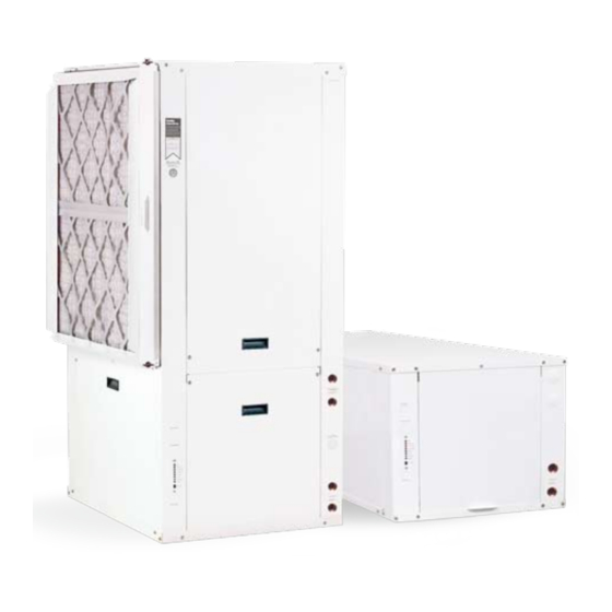
- Page 1 Water source heat pump rJ-series INSTALLATION, OPERATION & MAINTENANCE RJ Series New Release 146.00-NOM2 (310) Geothermal/Water Source Heat Pump • R-410A Refrigerant • 2, 2.5, 3, 3.5, 4, 5, 6 Ton Single Speed • 2, 3, 4, 5, 6 Ton Dual Capacity models: rJ*h / rJ*V stallation Information...
- Page 3 RJ Series Geothermal/Water Source Heat Pump • R-410A Refrigerant • 2, 2.5, 3, 3.5, 4, 5, 6 Ton Single Speed • 2, 3, 4, 5, 6 Ton Dual Capacity Installation Information Water Piping Connections Hot Water Generator Connections Electrical Startup Procedures Troubleshooting Preventive Maintenance 146.00-NOM2 03/10...
-
Page 5: Table Of Contents
RJ SERIES INSTALLATION MANUAL Table of Contents Model Nomenclature ............. 4 General Installation Information . -
Page 6: Model Nomenclature
RJ SERIES INSTALLATION MANUAL Model Nomenclature 19-20 Model Vintage RJS = Single Speed A = Current RJT = Dual Capacity Non-Standard Option Details Cabinet Configuration SS = Standard Option H = Horizontal QP = 2 in. MERV 13 Filter V = Vertical SF = Stainless Steel Drain Pan SG = 2 in. -
Page 7: General Installation Information
RJ SERIES INSTALLATION MANUAL General Installation Information Safety Considerations WARNING: Before performing service or maintenance operations on a system, turn off main power switches to the indoor unit. If applicable, turn off the accessory heater power switch. Electrical shock could cause personal injury. Installing and servicing heating and air conditioning equipment can be hazardous due to system pressure and electrical components. Only trained and qualified service personnel should install, repair or service heating and air conditioning equipment. Untrained personnel can perform the basic maintenance functions of cleaning coils and cleaning and replacing filters. -
Page 8: Vertical Dimensional Data
RJ SERIES INSTALLATION MANUAL Vertical Dimensional Data Top Air Discharge LEFT RETURN Field Installed Duct Flange Filter Rack Width Legend AP = Alternate Service Panel Access Panels AIR COIL BP = Blower Service Panel CP = Control Access Panel CMP = Compressor Service Panel 2´... - Page 9 RJ SERIES INSTALLATION MANUAL Vertical Dimensional Data cont. Bottomflow LEFT RETURN RIGHT RETURN 1.70 (4.3 cm) FILTER RACK CONNECTION FILTER RACK CONNECTION LEFT SIDE LEFT SIDE RIGHT SIDE 1.90 (4.7 cm) Optional 2´ [61cm] 2´ [61cm] FRONT Service Access Service Access Right Return (Opposite Side for Left Return)
- Page 10 RJ SERIES INSTALLATION MANUAL Vertical Dimensional Data cont. Rear Air Discharge AIR COIL Legend AP = Alternate Service Panel BP = Blower Service Panel CP = Control Access Panel CMP = Compressor Service Panel Power Supply 3/4 in. (19.1 mm) HV Knockout 1/2 in.
-
Page 11: Horizontal Dimensional Data
RJ SERIES INSTALLATION MANUAL Horizontal Dimensional Data Legend AP = Alternate Service Panel BP = Blower Service Panel Optional 2´ [61cm] FRONT FRONT CP = Control Access Panel Service Access CMP = Compressor Service Panel RIGHT RETURN LEFT RETURN 2ft [61cm] Service Access 2.1˝... -
Page 12: Installing Horizontal Units
RJ SERIES INSTALLATION MANUAL Installing Horizontal Units Remove and discard the compressor hold down shipping bolt located at the front of the compressor mounting bracket prior to setting the unit in place. Horizontal units are available with side or end discharge. Note: Left (Right) Return Side Discharge cannot be converted to Left (Right) Return End Discharge or vice versa, without additional custom sheet metal parts. -
Page 13: Duct System And Water Piping
RJ SERIES INSTALLATION MANUAL Duct System An air outlet collar is provided on vertical top and rear discharge units and all horizontal units to facilitate a duct connection (vertical bottom flow units have no collar). A flexible connector is recommended for discharge and return air duct connections on metal duct systems. Uninsulated duct should be insulated with a minimum of 1-inch duct insulation. -
Page 14: Water Quality
RJ SERIES INSTALLATION MANUAL Water Quality In ground water situations where scaling could be heavy or where biological growth such as iron bacteria will be present, a closed loop system is recommended. The heat exchanger coils in ground water systems may, over a period of time, lose heat exchange capabilities due to a buildup of mineral deposits inside. -
Page 15: Freeze Detection And Condensate Drain
RJ SERIES INSTALLATION MANUAL Freeze Detection Set SW2-2 on the printed circuit board for applications using a closed loop antifreeze solution to “LOOP” (15°F). On applications using an open loop/ground water system (or closed loop no antifreeze), set this dip switch to “WELL” (30°F), the factory default setting. (Refer to the Dip Switch Field Selection table). -
Page 16: System Cleaning And Flushing
RJ SERIES INSTALLATION MANUAL System Cleaning and Flushing Cleaning and Flushing Figure 7: Flushing with Water Prior to start up of any heat pump, the water circulating system must be cleaned and Shutoff Valve Equipped Systems flushed of all dirt and debris. If the system is equipped with water shutoff valves, the supply and return Return Runout runouts must be connected together at each unit location (This will prevent the introduction of dirt into the unit, see Figure 7). -
Page 17: Open Loop Ground Water Systems
RJ SERIES INSTALLATION MANUAL Open Loop Ground Water Systems Typical open loop piping is shown below. Always maintain water pressure in the heat exchanger by placing water control valves at the outlet of the unit to prevent mineral precipitation. Use a closed, bladder-type expansion tank to minimize mineral formation due to air exposure. -
Page 18: Electrical Connections
RJ SERIES INSTALLATION MANUAL Electrical Connections General Be sure the available power is the same voltage and phase as that shown on the unit serial plate. Line and low voltage wiring must be done in accordance with local codes or the National Electric Code, whichever is applicable. Unit Power Connection Connect the incoming line voltage wires to L1 and L2 of the contactor as shown in Figure 13C for single-phase unit. -
Page 19: Electronic Thermostat Installation
RJ SERIES INSTALLATION MANUAL Electrical Connections cont. Pump Wiring Figure 14: Pump Wiring 208-230/60/1 See Figure 14 for electrical connections from control box to pumps. TO PUMP Electronic Thermostat Figure 15: Thermostat Wiring Position the thermostat subbase against the wall so that it is level and the thermostat wires protrude through the middle of the subbase. -
Page 20: Electrical Data
RJ SERIES INSTALLATION MANUAL Electrical Data ECM Motor Total Compressor Rated Voltage Motor Unit Circ Fuse/ Model Voltage Min/Max LRA** HACR 208-230/60/1 197/253 29.0 10.2 11.8 265/60/1 238/292 28.0 11.1 208-230/60/1 197/253 33.5 12.4 14.5 265/60/1 238/292 28.0 11.4 13.2 208-230/60/1 197/253 14.0 48.0... - Page 21 RJ SERIES INSTALLATION MANUAL Electrical Data cont. PSC Motor Total Compressor Rated Voltage Motor Unit Circ Fuse/ Model Voltage Min/Max LRA** HACR 208-230/60/1 197/253 21.0 265/60/1 238/292 22.0 208-230/60/1 197/253 25.0 265/60/1 238/292 22.0 208-230/60/1 197/253 29.0 265/60/1 238/292 28.0 208-230/60/1 197/253 33.5 11.6...
-
Page 22: Setting Fan Speed
RJ SERIES INSTALLATION MANUAL Setting Fan Speed ECM2 fan motors have a 12-speed selector dip switch on the logic board (SW1) and are factory set for optimum performance. To change speeds, select the appropriate speeds on dip switch SW1. Consult the ECM2 fan performance table below for specific airflow and switch information. -
Page 23: Setting Fan Speed - Psc
RJ SERIES INSTALLATION MANUAL Fan Performance Data Standard PSC Motor Blower Airflow (cfm) at External Static Pressure (in. wg) Model Motor 0.05 0.10 0.15 0.20 0.25 0.30 0.35 0.40 0.45 0.50 0.60 0.70 0.80 0.90 1.00 Size RJS009 6 x 8 1/10 RJS012 6 x 8 1/10 RJS015 9 x 7 RJS018... -
Page 24: Wiring Schematics
RJ SERIES INSTALLATION MANUAL Wiring Schematics Standard Control 208-230/60/1... - Page 25 RJ SERIES INSTALLATION MANUAL Wiring Schematics cont. Standard Control 460-575/60/3 Refer to instructions below to change speeds . Notes: - High - L1 to white side of capacitor , L2 to H on motor. 1 - 24V Accessory relay (see SW2 - 3 for description of operation ) - Med - L1 to white side of capacitor , L2 to M on motor, orange wire to M1 on motor.
- Page 26 RJ SERIES INSTALLATION MANUAL Wiring Schematics cont. FX10 Control 265-270/60/1 GROUND 24VAC Com 24VAC...
- Page 27 RJ SERIES INSTALLATION MANUAL Wiring Schematics cont. FX10 Control 460/60/3 GROUND 24VAC Com 24VAC...
- Page 28 RJ SERIES INSTALLATION MANUAL Wiring Schematics cont. Dual Capacity Wiring Schematic - 208-230/60/1 Blue Black Unit Power 208-230/60/1 Blue Capacitor (10) NOTE 4 Blk/Wht(4) Gry/Wht(5) Blk/Wht (6) Transformer Switch NOTE 1 208V 240V Org(7) Brn(8) 208V 240V 240 V L2 240V L1 Fused L2 Fused L2...
- Page 29 RJ SERIES INSTALLATION MANUAL Wiring Schematics cont. Dual Capacity Wiring Schematic - 208-230/60/1 cont. With optional ' EA' Series Auxiliary Electric Heat Power Auxiliary Electric Heat 208-230/60/1 Typical schematic shown NOTE 5 Pink Pink Violet Gray Gray Pink Gray Gray Gray Gray ECM2...
- Page 30 RJ SERIES INSTALLATION MANUAL Wiring Schematics cont. Dual Capacity Wiring Schematic - 460/60/3 - ECM Notes: 1 - 460 volt units use a 265 volt singe phase ECM motor which requires a dedicated neutral from the Unit Power service panal. 2 - 24V Accessory relay (see SW 2 - 3 for description of operation) 460/60/3 3 - Dual capacity units only.
- Page 31 RJ SERIES INSTALLATION MANUAL Wiring Schematics cont. Single Speed Wiring Schematic - 460-575/60/3 - PSC Refer to instructions below to change speeds . - High - L1 to white side of capacitor, L2 to H on motor. - Med - L1 to white side of capacitor, L2 to M on motor, orange wire to M1 on motor .
-
Page 32: Rj Series Controls - Premier Microprocessor
RJ SERIES INSTALLATION MANUAL RJ Series Controls - Premier Microprocessor Standard Premier Microprocessor Safety Controls The control receives separate signals for a high pressure switch for safety, a low pressure switch to prevent loss of charge damage, and a low suction temperature thermistor for freeze sensing. Upon a continuous 30-second measurement of the fault (immediate for high pressure), compressor operation is suspended, the appropriate lockout LED begins flashing. - Page 33 RJ SERIES INSTALLATION MANUAL RJ Series Controls - Premier Microprocessor cont. Heat, 3rd Stage (Y1,Y2,W) Dual Capacity Units determines the “medium speed fan” setting, and the third “on” switch determines the “high speed fan” setting. The 1st stage of resistance heat is energized 10 seconds after “W” input, and with continuous 3rd stage demand, the additional stages Lockout Conditions of resistance heat engage sequentially every 5 minutes.
- Page 34 RJ SERIES INSTALLATION MANUAL RJ Series Controls - Premier Microprocessor cont. DIP Switch Settings Prior to powering unit, ensure that all DIP switches on SW2 & SW3 are set properly according to the tables below. FACTORY SETUP DIP SWITCHES (SW3) DIP SWITCH DESCRIPTION OFF POSITION ON POSITION NUMBER Dual Capacity/Single-Speed Dual Capacity SW 3- Single-Speed Operation...
- Page 35 RJ SERIES INSTALLATION MANUAL RJ Series Controls - Premier Microprocessor cont. Operation Logic Data Table HEATING COOLING OPERATION LOGIC Blower ON SL1 - IN ON STG1 STG2 STG3 EMERG STG1 STG2 SINGLE SPEED UNITS Compressor High High High High ECM2 Normal High High High 85% Med 85% High ECM2 Dehumidify Rev Valve Loop Pump Staged Staged Aux Heater...
-
Page 36: Troubleshooting
RJ SERIES INSTALLATION MANUAL Troubleshooting Standard Microprocessor Controls To check the unit control board for proper operation: Disconnect thermostat wires at the control board. Jumper the desired test input (Y1, Y2, W, O or G) to the R terminal to simulate a thermostat signal. If control functions properly: •... -
Page 37: Optional Controls - Fx10
RJ SERIES INSTALLATION MANUAL Optional Controls - FX10 FX10 Advanced Control Overview The Johnson Controls FX10 board is specifically designed for commercial heat pumps and provides control of the entire unit as well as input ports for Open N2, LonTalk, BACnet (MS/TP @ 19,200 Baud rate) communication protocols as well as an input port for a user interface. - Page 38 RJ SERIES INSTALLATION MANUAL Optional Controls - FX10 cont. FX10 Control Overview DDC Operation and Connection The FX10 is a microprocessor based control that not only monitors Other optional network protocol boards that can be added to the and controls the heat pump but also can communicate any of this FX10 are: information back to the building automation system (BAS).
- Page 39 RJ SERIES INSTALLATION MANUAL Optionals Control - FX10 cont. High Pressure (BI-11) the control receives a call to start the compressor. This delay is adjustable from 30 – 300 seconds over a BAS or a MUI. If the The high-pressure switch shall be a normally closed (NC) switch control is in test mode the Compressor Fixed On Delay Timer will that monitors the systems refrigerant pressure.
- Page 40 RJ SERIES INSTALLATION MANUAL Optional Controls - FX10 cont. Cooling Cycle Network Enabled Output/Electric Heat Output (BO-5) On a call for cooling, the blower enable output and accessory This output can be enabled by the BAS network for use as output 2 will turn on immediately after the random start delay timer needed in the field.
- Page 41 RJ SERIES INSTALLATION MANUAL Optional Controls - FX10 cont. FX10 User Interface (MUI) Physical Layout Power LED Alarm LED Up Arrow Right Arrow Escape (ESC) LED 1 Button Return Button LED 4 LED 8 Left Arrow Down Arrow Alarm LED - Indicates a Lock-Out or a bad Freeze Sensor LED 3 - On shows Fan running Power LED - Shows FX processor is operational LED 4 - On shows Reversing Valve in cool...
- Page 42 RJ SERIES INSTALLATION MANUAL Optional Controls - FX10 cont. MUI Menu Navigation for Single Compressor - RJ Series Water-to-Air Maint LOG_IN REQUIRED Maintenance User : <= maint => MinClgSetpt 60.0 ºF Code : 5667 MaxHtgSetpt 89.9 ºF W Coil LoLim1 30.0 ºF Press right arrow key W Coil LoLim2 15.0 ºF one time from TmpOccTime...
- Page 43 RJ SERIES INSTALLATION MANUAL Optional Controls - FX10 cont. Some Cool Heading - N2 N2 Open Point Description Point Type Point Address Long Name nciSetpoints.Occupied_Co Occupied Cooling Setpoint Input (Read/Write) nciSetpoints.Standby_Coo Standby Cooling Setpoint Input (Read/Write) nciSetpoints.Unoccupied_ Unoccupied Cooling Setpoint Input (Read/Write) nciSetpoints.Occupied_He Occupied Heating Setpoint Input (Read/Write) nciSetpoints.Standby_Hea Standby Heating Setpoint Input (Read/Write) nciSetpoints.Unoccupi5#6...
- Page 44 RJ SERIES INSTALLATION MANUAL Optional Controls - FX10 cont. Some Cool Heading - LonWorks LonWorks Point Description LonWorks Name SNVT Type SNVT Index SCPT Reference SCPT Index UCPT Index Occupied Cooling Setpoint Input (Read/Write) Standby Cooling Setpoint Input (Read/Write) Unoccupied Cooling Setpoint Input (Read/Write) nciSetpoints SNVT_temp_setpt SCPTsetPnts...
- Page 45 RJ SERIES INSTALLATION MANUAL Optional Controls - FX10 cont. Some Cool Heading - BACNet BACnet Point Description Object Identifier Property Full Reference Object Type Type Enumeration Instance Name Enumeration Analog Value Present_Value WFI##########.Occupied Cool.Present_Value Occupied Cooling Setpoint Input (Read/Write) Standby Cooling Setpoint Input (Read/Write) Analog Value Present_Value WFI##########.Unoccupied Cool.Present_Value...
- Page 46 RJ SERIES INSTALLATION MANUAL Optional Controls - FX10 cont. BACnet Variables Analog Value (Type 2) The variables will be listed with the point type and instance preced- ing the variable name. 2:1 Occupied Cool [Write, Cooling setpoint in Occupied mode] Analog Input (Type 0) 2:2 Unoccupied Cool [Write, Cooling setpoint in Unoccupied mode] 0:1 Space Temp 2:3...
- Page 47 RJ SERIES INSTALLATION MANUAL Optional Controls - FX10 cont. BACnet Variables [Read, shows the BO5 (electric heat) output value, Inactive=Off, Active=On] 3:10 BO9 Output [Read, shows the BO9 output value, Inactive=Off, Active=On] Multistate Input (Type 13) 13:1 Effective Occupancy [Read, show the prevailing occupancy status of the heatpump1=Occupied, 2=Unoccupied, 3=Bypass, 255=Invalid] 13:2...
-
Page 48: Unit Startup
RJ SERIES INSTALLATION MANUAL Unit Startup Before Powering Unit, Check The Following: Note: Remove and discard the compressor hold down shipping bolt located at the front of the compressor mounting bracket. The bolt can then be discarded. • High voltage is correct and matches nameplate. •... -
Page 49: Operating Parameters
RJ SERIES INSTALLATION MANUAL Operating Parameters Single Speed Models Cooling -- No Hot Water Generator Entering Water Water Flow Suction Discharge 009-070 009-070 Water Temp Air Temp Drop Temp °F GPM/Ton Pressure PSIG Pressure PSIG Superheat Subcooling Rise °F °F DB 133 - 148 205 - 225 17 - 26 10 - 14... - Page 50 RJ SERIES INSTALLATION MANUAL Operating Parameters cont. Dual Capacity Models FIRST STAGE OPERATION Cooling -- No Hot Water Generator Entering Water Water Flow Suction Discharge Water Temp Air Temp Drop Temp °F GPM/Ton Pressure PSIG Pressure PSIG Superheat Subcooling Rise °F °F DB 125-140 205-225 12-20 8-14...
-
Page 51: Operating Limits
RJ SERIES INSTALLATION MANUAL Operating Limits Cooling Heating Operating Limits (°F) (°C) (°F) (°C) Air Limits Min. Ambient Air Rated Ambient Air 26.7 21.1 Max. Ambient Air 37.8 29.4 Min. Entering Air 10.0 Rated Entering Air db/wb 80.6/66.2 27/19 20.0 Max. -
Page 52: Startup/Troubleshooting Form
RJ SERIES INSTALLATION MANUAL DEALER: PHONE #: DATE: PROBLEM: MODEL #: Startup/Troubleshooting Form SERIAL #: COOLING CYCLE ANALYSIS SAT °F °F Unit Amp Draw: Loop: Open Closed Line Voltage: °F °F COIL SUCTION COMPRESSOR REVERSING COAX COAX EXPANSION VALVE LOAD SOURCE VALVE DISCHARGE... -
Page 53: Pressure Drop
RJ SERIES INSTALLATION MANUAL Pressure Drop Single Speed Models Dual Capacity Models Pressure Drop (psi) Pressure Drop (psi) Model Model 30°F 50°F 70°F 90°F 110°F 30°F 50°F 70°F 90°F 110°F 026 full load 026 part load 038 full load 038 part load 049 full load 049 part load 064 full load... -
Page 54: Preventive Maintenance
RJ SERIES INSTALLATION MANUAL Preventive Maintenance Water Coil Maintenance 1. Keep all air out of the water. An open loop system should be checked to ensure that the well head is not allowing air to infiltrate the water line. Lines should always be airtight. 2. - Page 55 RJ SERIES INSTALLATION MANUAL Notes...
- Page 56 © 2010 Johnson Controls, Inc. P.O. Box 423, Milwaukee, WI 53203 Printed in USA 146.00-NOM2 (310) www.johnsoncontrols.com New Release...
Need help?
Do you have a question about the RJ H Series and is the answer not in the manual?
Questions and answers