Table of Contents
Advertisement
Quick Links
Advertisement
Table of Contents

Related Manuals for Johnson Controls RC Series


Summary of Contents for Johnson Controls RC Series
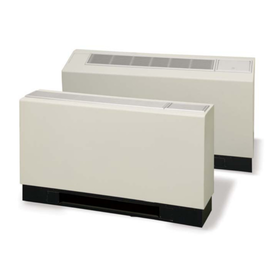
- Page 1 RC Series CONSOLE Geothermal/Water Source Heat Pump • R-410A Refrigerant • 0.75-1.5 Ton Single Speed Design Features Factory Options Accessories Dimensional Data Physical Data Performance Data Engineering Guide Specifi cations Form: 146.00-EG4A (0315) Supercedes: 146.00-EG4 (0210)
-
Page 3: Table Of Contents
Inside the RC Series Console ........ -
Page 4: Model Nomenclature
Rev.: 04 March 2015D Note: Chassis only available with left piping option FX10 option is only available with remote wall-mounted thermostat control. All RC Series product is Safety listed under UL1995 thru ETL and performance listed with AHRI in accordance with standard 13256-1. - Page 5 RC SERIES ENGINEERING GUIDE AHRI/ISO 13256-1 Performance Ratings ECM Motors AHRI/ASHRAE/ISO 13256-1 English (IP) Units Water Loop Heat Pump Ground Water Heat Pump Ground Loop Heat Pump Flow Rate Cooling Heating Cooling Heating Cooling Heating Model EWT 86°F EWT 68°F EWT 59°F...
- Page 6 RC SERIES ENGINEERING GUIDE Performance Standard (AHRI/ISO/ASHRAE 13256-1) The performance standard AHRI/ASHRAE/ISO 13256-1 became effective January 1, 2000 and replaces ARI Standards 320, 325, and 330. This new standard has three major categories: Water Loop (comparable to ARI 320), Ground Water (ARI 325), and Ground Loop (ARI 330).
-
Page 7: The Rc Series Console
This efficiency means the RC Series requires less loop than any product on the market. This can mean significant savings on commercial projects. Quiet Operation... -
Page 8: Inside The Rc Series Console
Inside the RC Series Console Refrigerant Service Connections and Serviceability RC Series products all feature zero ozone depletion and low global warming potential refrigerant R-410A. Two Schrader service ports are provided in every unit. The suction side and discharge side ports are for field charging Cabinet and servicing access. -
Page 9: Controls
Compressor control module (CCM) controls are standard on the • Lockout circuit to shut down unit operation upon receipt of a fault RC Series console heat pump. This control features unit mounted indicator from the safety controls. thermostat and switches, •... - Page 10 RC SERIES ENGINEERING GUIDE Controls cont. The user selects either “Heat/Cool” or “Fan Only” on the mode switch, Optional Versatec Microprocessor then either “High” or “Low” at the fan speed switch. The temperature Control Features can be controlled by rotating the thermostat control knob.
- Page 11 RC SERIES ENGINEERING GUIDE Controls cont. Control Tables for Optional Versatec Microprocessor Logic Board DIP Switch Settings Switch SW1 - 1 Test - Selected timings sped up to facilitate troubleshooting Normal - Standard timings SW1 - 2 Loop - Closed loop freeze sensing setting (15°F) Well - Open loop freeze sensing setting (30°F)
- Page 12 • LonTalk • BACnet (MS/TP @ 19,200 Baud rate) FX10 Advanced Control Overview The Johnson Controls FX10 board is specifically designed for Display commercial heat pumps and provides control of the entire unit as well as input ports for Open N2, LonTalk, BACnet (MS/TP @ Requires DLI Card/Kit.
- Page 13 There are two options for zone sensors that can be used with the from starting and enabling the alarm output (BO-6). The lockout FX10 control. Both sensors use a Johnson controls A99 positive condition can be reset by powering down the controller, by a temperature coefficient type sensor.
- Page 14 RC SERIES ENGINEERING GUIDE Controls - FX10 cont. temperature drops below the freeze detection limit trip point for the Sequence of Operation recognition delay period, the condition will be recognized as a fault. Power Fail Restart The freeze detection limit trip point will be factory set for 30°F and When the controller is first powered up, the outputs will be will be field selectable for 15°F by removing a jumper wire on BI-5.
- Page 15 RC SERIES ENGINEERING GUIDE Controls - FX10 cont. Cooling Cycle Control Accessories Zone Sensors On a call for cooling, the blower enable output and accessory output 2 will turn on immediately after the random start delay timer • TAXXJ02 Room Command Module •...
-
Page 16: Application Notes
Using a typical RC Series, one unit A decentralized system also means if one unit should fault, the of electricity will move four to five units of heat. - Page 17 • Closed Loop/Ground Water Plate Heat Exchanger Systems utilize lake, ocean, well water or other water sources to maintain closed loop water temperatures in multi-unit RC Series systems. A plate frame heat exchanger isolates the units from any contaminating effects of the water source, and allows periodic cleaning of the heat exchanger during off peak hours.
- Page 18 RC SERIES ENGINEERING GUIDE Application Notes cont. • Closed Loop /Cooler-Boiler Systems utilize a closed heat Cooler/Boiler - Closed Loop recovering loop with multiple water source heat pumps in the more conventional manner. Typically a boiler is employed to maintain closed loop temperatures above 60°F and a cooling tower to...
- Page 19 RC SERIES ENGINEERING GUIDE Application Notes cont. Typical Unit Installation WARNING: Before performing service or maintenance operations on a system, turn off main power switches to the Unit Location indoor unit. If applicable, turn off the accessory heater power Locate the unit in an indoor area that allows for easy removal of switch.
- Page 20 RC SERIES ENGINEERING GUIDE Application Notes cont. Water Piping Condensate Drain Piping is usually design as ‘reverse return’ to equalize flow paths On console units, the internal condensate drain assembly consists through each unit. A short flexible pressure rated hose is used to of a drain tube which is connected to the drain pan.
-
Page 21: Selection Example
RC SERIES ENGINEERING GUIDE Selection Example To achieve optimal performance, proper selection of each heat be selected on cooling capacity only since the heating output is pump is essential. A building load program should be used to usually greater than the cooling capacity. - Page 22 Antifreeze solution is Propylene Glycol 20% by weight. Determine the corrected heating and cooling performance at 30°F and 90°F respectively as well as pressure drop at 30°F for an RC Series Console RC18. The corrected cooling capacity at 90°F would be: 17,100 MBtuh x 0.969 = 16,569 MBtuh The corrected heating capacity at 30°F would be: 14,300 MBtuh x 0.913 = 13,056 MBtuh...
-
Page 23: Dimensional Data
RC SERIES ENGINEERING GUIDE Dimensional Data - Flat Top Cabinet RCW09-18 Overall Cabinet Flat Top Configuration Grille Grille Width Depth Height Grille Lid Length Width 45.0 10.8 25.7 35.0 44.1 10.3 09-12 114.3 27.3 65.2 23.4 88.9 15.6 5.8 112.0 26.0 10.9 50.0 12.3... - Page 24 RC SERIES ENGINEERING GUIDE Dimensional Data - Slope Top Cabinet RCS09-18 Overall Cabinet Slope Top Configuration Grille Grille Width Depth Height Grille Lid Length Width 45.0 11.1 28.6 35.0 44.1 10.3 09-12 114.3 28.2 72.6 23.4 88.9 15.6 7.2 112.0 26.0 10.9 50.0 12.6...
- Page 25 RC SERIES ENGINEERING GUIDE Dimensional Data - Extended Slope Top Cabinet RCE09-18 Overall Cabinet Ext. Slope Top Configuration Grille Grille Width Depth Height Grille Lid Length Width 50.0 12.6 29.1 35.0 49.1 12.0 09-12 127.0 32.0 73.9 23.4 88.9 15.6 6.1 124.7 30.5 10.9...
- Page 26 RC SERIES ENGINEERING GUIDE Dimensional Data - Right Return Controls Detail...
- Page 27 RC SERIES ENGINEERING GUIDE Dimensional Data - Right Return Chassis Data = inches (cm) Models 09-12 Models 15-18 37.88 42.88 (96.2) (108.9) 9.38 28.5 8.88 34.0 (23.8) (72.4) (22.6) (86.4) CONTROL PANEL CONTROL PANEL (3.8) (3.8) BLOWER ACCESS PANEL BLOWER ACCESS PANEL...
- Page 28 RC SERIES ENGINEERING GUIDE Dimensional Data - Left Return Controls Detail...
- Page 29 RC SERIES ENGINEERING GUIDE Dimensional Data - Left Return Chassis Data = inches (cm) Models 09-12 Models 15-18 37.88 42.88 (96.2) (108.9) 28.5 9.38 34.0 8.88 (72.4) (23.8) (86.4) (22.6) CONTROL PANEL CONTROL PANEL 1.50 1.50 (3.8) (3.8) 1.50 1.50 (3.8)
- Page 30 RC SERIES ENGINEERING GUIDE Operating Limits Cooling Heating Operating Limits (°F) (°C) (°F) (°C) Air Limits Min. Ambient Air Rated Ambient Air 26.7 21.1 Max. Ambient Air 37.8 29.4 Min. Entering Air 10.0 Rated Entering Air db/wb 80.6/66.2 27/19 20.0 Max.
-
Page 31: Physical Data
RC SERIES ENGINEERING GUIDE Physical Data Consoles Model Compressor (1 each) LG Rotary Factory Charge R410A, oz [kg] 27 [0.77] 27 [0.77] 36 [1.02] 34 [0.96] Fan Motor & Blower Fan Motor Type/Speeds 3 Speeds Fan Motor- hp [W] 0.25 [186] 0.25 [186]... - Page 32 RC SERIES ENGINEERING GUIDE Electrical Data ECM Motor Compressor Total Rated Voltage Model Motor Unit Circ Fuse/ Voltage Min/Max HACR 115/60/1 104/127 12.5 50.0 4.25 12.3 14.3 208-230/60/1 187/253 21.0 10/15 265/60/1 238/292 22.0 10/15 115/60/1 104/127 14.8 50.0 4.25 13.8...
-
Page 33: Auxiliary Heat Ratings
RC SERIES ENGINEERING GUIDE Auxiliary Heat Ratings ECM Motors Heater Heater Total Min. Max. Rated Voltage Model Element Motor Element Unit Circuit Fuse/ Voltage Min./Max. Watts Amp. Brkr. 208/60/1 197/254 2.45 3.93 09-12 230/60/1 197/254 1000 2.60 4.35 (1 kW) -
Page 34: Reference Calculations
RC SERIES ENGINEERING GUIDE Reference Calculations Heating Calculations: Cooling Calculations: LWT = EWT + LWT = EWT - GPM x 500 GPM x 500 LAT (DB) = EAT (DB) - LAT = EAT + CFM x 1.08 CFM x 1.08... -
Page 35: Correction Factor Tables
RC SERIES ENGINEERING GUIDE Correction Factor Tables Cooling Capacity Corrections Sensible Cooling Capacity Multipliers - Entering DB ºF Entering Total Power Heat of Air WB ºF Clg Cap Input Rejection 80.6 0.898 0.723 0.866 1.048 1.185 0.985 0.913 0.912 0.632 0.880... - Page 36 RC SERIES ENGINEERING GUIDE RC09...
- Page 37 RC SERIES ENGINEERING GUIDE RC12...
- Page 38 RC SERIES ENGINEERING GUIDE RC15...
- Page 39 RC SERIES ENGINEERING GUIDE RC18...
-
Page 40: Wiring Schematics
RC SERIES ENGINEERING GUIDE Wiring Schematics CCM - with ECM, Electric Heat and Electronic Stat 208-230-265/60/1 Blue Compressor Unit Power Supply Motor Ground 208-230/60/1 or Blue 265-277/60/1 Handi - Box Motor White White Tan (33) Module Green/Yellow Brown (26) Note 5... - Page 41 RC SERIES ENGINEERING GUIDE Wiring Schematics, cont. FX10 - with ECM Motor, ELectric Heat and Remote Stat Blue Compressor Motor Unit Power Supply 208-230/60/1 or Ground 265/60/1 Handi - Box White White Motor Module Green/Yellow Fan Speed Switch Note 6...
- Page 42 RC SERIES ENGINEERING GUIDE Wiring Schematics cont. Microprocessor - with ECM Motor Electric Heat and Remote Stat 208-230-265/60/1 Compressor Blue Motor Blue Unit Power Supply 208-230/60/1 or Black Ground 265-277/60/1 Motor Tan (36) White White Module Handi - Box Green/Yellow...
- Page 43 RC SERIES ENGINEERING GUIDE Wiring Schematics cont. Microprocessor - with ECM Motor Electric Heat and Remote Stat 208-230-265/60/1 Normal Mode Control Timing Table Fan off delay 30 seconds Compressor on delay 10 seconds Compressor short cycle delay 5 minutes Minimum compressor on time...
- Page 44 RC SERIES ENGINEERING GUIDE Wiring Schematics cont. CCM - with ECM Motor and Electronic Stat 208-230-265/60/1 Motor Compressor Blue Unit Power Supply Motor Ground 208-230/60/1 or Module 265-277/60/1 Green/Yellow Handi - Box Tan (33) Brown (26) Note 4 Black (31)
-
Page 45: Engineering Guide Specifications
RC SERIES ENGINEERING GUIDE Engineering Guide Specifi cations General Compressors shall be high-efficiency single speed rotary type designed for heat pump duty and mounted on durometer grommets Furnish and install Water Source Heat Pumps, as indicated on the to provide vibration free compressor mounting. Compressor motors plans. - Page 46 RC SERIES ENGINEERING GUIDE Engineering Guide Specifi cations cont. mounted thermostat shall be the standard thermostat option. Hose Kits - Automatic Balancing and Ball Valves All unit mounted thermostats shall be auto changeover. Manual (field-installed) changeover WILL NOT be accepted. Electromechanical operation A flexible steel braid hose featuring Kevlar®...
- Page 47 RC SERIES ENGINEERING GUIDE Notes...
-
Page 48: Revision Guide
RC SERIES ENGINEERING GUIDE Revision Guide Pages: Description: Date: Obsoleted PSC Option, Updated Nomenclature, Updated Wiring Schematics 04 Mar 2015 Updated with All-Aluminum Air Coils 07 Mar 2014 Added Revision Table 07 Mar 2014... - Page 51 Product: RC Series Console Type: Geothermal/Water Source Heat Pump Size: 0.75-1.5 Ton Document Type: Engineering Guide Form: 146.00-EG4A (0314) Supercedes: 146.00-EG4 (0210)
Need help?
Do you have a question about the RC Series and is the answer not in the manual?
Questions and answers