Advertisement
Available languages
Available languages
Quick Links
743A6
Gebrauchsanleitung (Techniker / Benutzer) ������������������������������������������������������������������� 2
Instructions for use (technician / user) ������������������������������������������������������������������������ 12
Mode d'emploi (Technicien / Utilisateur) � ��������������������������������������������������������������������� 22
Instrucciones de uso (técnicos / usuarios) ������������������������������������������������������������������� 32
Advertisement
Chapters

Related Manuals for Otto Bock 743A6


Summary of Contents for Otto Bock 743A6
- Page 1 743A6 Gebrauchsanleitung (Techniker / Benutzer) ������������������������������������������������������������������� 2 Instructions for use (technician / user) ������������������������������������������������������������������������ 12 Mode d’emploi (Technicien / Utilisateur) � ��������������������������������������������������������������������� 22 Instrucciones de uso (técnicos / usuarios) ������������������������������������������������������������������� 32...
-
Page 2: Table Of Contents
Inhaltsverzeichnis ________________________________________________ 1 Einleitung ..........................3 2 Anwendungsbereich ......................3 3 Bauteile ..........................3 4 Montage der 743A6 Aufbauhilfe .................... 4 5 Funktion und Beschreibung der Bauteile ................4 6 Anwendungsbeispiele ......................8 7 Haftung ..........................11 2 | Ottobock... -
Page 3: Einleitung
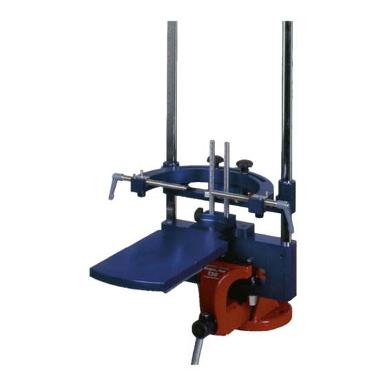
Knie am Gipsnegativ oder Gipspositiv konzipiert. Für die Verwendung wird die Orthesen-Aufbauhilfe im Schraubstock fixiert. _________________________________________________________________________ 3 Bauteile Basisteil Doppelkegel Zylinderstift Fußplatte Klemmhebel Absatzplatte Einstellsäule Führungssäule Aufnahmegabel Höhenverstelleinheit Sterngriffschraube untere Verschiebeplatte Spindel Stabaufnahme, 4 Stück Vierkantachse, 2 Stück 743A6 Ottobock | 3... -
Page 4: Montage Der 743A6 Aufbauhilfe
Montage der 743A6 Aufbauhilfe 4 Montage der 743A6 Aufbauhilfe _______________________________________________ Die Orthesen-Aufbauhilfe mit ihren Bauteilen kann über das Basisteil (1) im Schraubstock fixiert werden. Durch die integrierten Zylinderstifte (3) im Basisteil wird eine horizontale Ausrichtung im Schraubstock erleichtert. 5 Funktion und Beschreibung der Bauteile _____________________________________ Die auf dem Basisteil angebrachte Fußplatte (4) läßt... - Page 5 Einstellsäule (7) abgelesen werden. An den Führungssäulen (8) sind die Aufnahmegabeln (9) für die Knöchelgelenk- und Kniegelenksachse höhenverstellbar angebracht. Zur Höhenverstellung der Aufnahmegabeln wird le- diglich der Klemmhebel an der Höhenverstelleinheit (10) gelockert und anschließend wieder festgezogen. 743A6 Ottobock | 5...
- Page 6 Verschiebeplatte (12) sind 50 mm Verschie- beweg möglich. Für eine unterschiedliche Rotationsstellung von hori- zontaler Knie- und Knöchelachse kann die entspre- chende Aufnahmegabel durch Lockern der jeweils zwei Sterngriffschrauben nach beiden Seiten um 30° rotiert werden. 6 | Ottobock 743A6...
- Page 7 Weitenmaß in beiden Aufnahmegabeln bis 210 mm erreicht werden. Die Spindelaufnahme kann aus der Aufnahmegabel demontiert werden, dazu wird die dazugehörige Sterngriffschraube gelöst. Soll das Gipsmodell über Rundstahl ausgerichtet werden, werden hierfür die vorgesehenen Stabauf- nahmen (14) eingesetzt. 743A6 Ottobock | 7...
-
Page 8: Anwendungsbeispiele
Aufnahmegabeln eingelegt werden. __________________________________________________________ 6 Anwendungsbeispiele Übertragung der relevanten Markierungen (z.B. Knie- und Knöcheldrehpunkte) im Gipsnegativ vornehmen. Gipsnegativ auf die Fußplatte stellen und zwischen den Aufnahmegabeln im Knie und im Knöchel durch Verstellen der Spindeln einspannen. 8 | Ottobock 743A6... - Page 9 Hilfe des LaserLine-Gerätes 743L30=*. Sollen die Drehpunkte mit einem Rundstahl markiert werden, werden die Spindelaufnahmen mit der Spin- del gegen die Stabaufnahmen ausgewechselt (siehe Kap. 5, Hinweise zu (14)) und das Gipsmodell in den Aufnahmegabeln ausgerichtet. 743A6 Ottobock | 9...
- Page 10 Vierkantachsen nach dem Einfetten mit Gipsisoliercreme 640Z5=1/640Z5=5 mit Gips- Longuetten gesichert. Bei eingespanntem Gipspositiv kann der Vorfuß mit Gips aufgebaut werden. Die Fußplatte muss dabei zum Schutz mit Gipsisoliercreme an den Kontaktstellen isoliert werden. 10 | Ottobock 743A6...
-
Page 11: Haftung
Bedingungen und zu den vorge- die durch Bauteile und Ersatzteile verursacht werden, gebenen Zwecken eingesetzt wird. Der Hersteller die nicht vom Hersteller freigegeben wurden, haftet empfiehlt das Produkt sachgemäß zu handhaben und der Hersteller nicht. 743A6 Ottobock | 11... - Page 12 1 Introduction ..........................13 2 Area of application ......................... 13 3 Components ........................... 13 4 Mounting the 743A6 alignment aid ..................14 5 Function and description of the components ................ 14 6 Application examples ......................18 7 Liability ........................... 21...
-
Page 13: Introduction
3 Components ______________________________________________________ Base part Double cone Cylinder pin Footplate Clamping lever Heel plate Adjustment column Guide column Holding fork Height adjustment unit Star grip screw Lower slider plate Spindle Rod attachments, 4 Square shafts, 2 743A6 Ottobock | 13... -
Page 14: Mounting The 743A6 Alignment Aid
Mounting the 743A6 alignment aid 4 Mounting the 743A6 alignment aid __________________________________ The orthotic alignment aid can be secured in a vice using the base part (1). The integrated cylinder pins (3) in the base part make horizontal alignment in the vice easier. 5 Function and description of the components... - Page 15 Height-adjustable holding forks (9) for the ankle joint and knee joint are attached to the guide columns (8). To adjust the height of the holding forks, sim- ply loosen the clamping lever on the height adjustment unit (10) and then retighten it. 743A6 Ottobock | 15...
- Page 16 (12) can be displaced by 50 mm. For a different rotational adjustment of the horizontal knee and ankle axis, the corresponding holding fork can be rotated 30° to either side by loosening the two star grip screws in each case. 16 | Ottobock 743A6...
- Page 17 The spindle attachment can be removed from the holding fork by unscrewing the corresponding star grip screw. If the plaster model is to be aligned with round steel, the rod attachments (14) provided for this are used. 743A6 Ottobock | 17...
-
Page 18: Application Examples
Transfer of the relevant markings (e.g., knee and ankle pivot points) in the plaster negative. Place the plaster negative on the footplate and clamp it between the holding forks at the knee and ankle by adjusting the spindles. 18 | Ottobock 743A6... - Page 19 If the pivot points are to be marked with round steel, the spindle attachments are replaced with the rod attachments (see sec. 5, note on (14)), and the plaster model is aligned in the holding forks. 743A6 Ottobock | 19...
- Page 20 640Z5=1/640Z5=5 plaster isolation cream with plaster longuettes. The forefoot can be built up with plaster while the plaster positive is clamped in. When doing this, the footplate must be isolated with plaster isolation cream at the contact points for protection. 20 | Ottobock 743A6...
-
Page 21: Liability
The manufacturer recommends spare parts not approved by the manufacturer. that the product be used and maintained according 743A6 Ottobock | 21... - Page 22 Sommaire _______________________________________________________ 1 Introduction ..........................23 2 Domaine d’application ......................23 3 Composants .......................... 23 4 Montage de l’aide à l’alignement 743A6 ................24 5 Description et fonctionnement des composants ..............24 6 Exemples d’utilisation ......................28 7 Responsabilité ........................31...
-
Page 23: Introduction
Levier de serrage Plaque de talon Colonne de réglage Colonne de guidage Fourche de positionnement Unité de réglage de la hauteur Poignée-étoile Plaque de translation inférieure Broche Logement pour tige, 4 pièces Axe carré, 2 pièces 743A6 Ottobock | 23... -
Page 24: Montage De L'aide À L'alignement 743A6
Montage de l’aide à l’alignement 743A6 4 Montage de l’aide à l’alignement 743A6 _____________________________ Le dispositif d’aide à l’alignement d’orthèses et ses composants peuvent être serrés dans un étau au niveau de la base (1). Les goupilles cylindriques (3) intégrées dans la base simplifient le positionnement horizontal dans l’étau. - Page 25 (8) et sont réglables en hauteur. Pour régler la hauteur des fourches de positionnement, il suffit de desserrer le levier de serrage au niveau de l’unité de réglage de la hauteur (10), puis de le resserrer. 743A6 Ottobock | 25...
- Page 26 50 mm. Pour modifier la position de rotation de l’axe horizontal du genou et de la cheville, la fourche de positionne- ment correspondante peut être tournée de 30° des deux côtés. Pour cela, desserrez la poignée-étoile correspondante. 26 | Ottobock 743A6...
- Page 27 Le logement de la broche peut être démonté de la fourche de positionnement. Pour cela, desserrez la poignée-étoile correspondante. Si le modèle en plâtre doit être orienté avec de l’acier rond, utilisez les logements pour tige (14) prévus à cet effet. 743A6 Ottobock | 27...
-
Page 28: Exemples D'utilisation
Placer le négatif en plâtre sur la plaque de pied et le serrer entre les fourches de positionnement au niveau du genou et de la cheville en réglant les broches. 28 | Ottobock 743A6... - Page 29 Si les points de rotation doivent être repérés avec de l’acier rond, la broche et son logement sont remplacés par des logements pour tige (voir chap. 5, consignes pour le composant (14)) et orienter le modèle en plâtre dans les fourches de positionnement. 743A6 Ottobock | 29...
- Page 30 L’avant-pied peut être aligné avec du plâtre sur le positif en plâtre serré. Pour sa protection, la plaque de pied doit alors être isolée au niveau des zones de contact avec de la crème isolante pour plâtre. 30 | Ottobock 743A6...
-
Page 31: Responsabilité
Le fabricant conseille découlant de l’utilisation de composants et de pièces de manier le produit conformément à son usage et de de rechange qu’il n’a pas autorisés. 743A6 Ottobock | 31... - Page 32 1 Introducción ………………………………………………………………………………………… 33 2 Ámbito de aplicación ……………………………………………………………………………… 33 3 Componentes ……………………………………………………………………………………… 33 4 Montaje del alineador 743A6 …………………………………………………………………… 34 5 Función y descripción de los componentes …………………………………………………… 34 6 Ejemplos de uso …………………………………………………………………………………… 38 7 Responsabilidad …………………………………………………………………………………… 41...
-
Page 33: Introducción
Placa para el tacón Columna de ajuste Columna de guía Horquilla de alojamiento Unidad de regulación de la altura Tornillo con empuñadura en estrella Placa inferior de desplazamiento Husillo Alojamiento de varilla, 4 unidades Eje cuadrado, 2 unidades 743A6 Ottobock | 33... -
Page 34: Montaje Del Alineador 743A6
Montaje del alineador 743A6 4 Montaje del alineador 743A6 ________________________________________ El alineador de órtesis con sus componentes se puede fijar al tornillo de banco mediante la pieza básica (1). Los pasadores cilíndricos (3) integrados en la pieza básica facilitan la orientación horizontal en el tornillo de banco. - Page 35 Para regular la altura de las horquillas de aloja- miento solo hay que aflojar la palanca de su- jeción de la unidad de regulación de la altu- ra (10) y, a continuación, volver a apretarla. 743A6 Ottobock | 35...
- Page 36 Para ajustar una posición de rotación distinta en los ejes horizontales de la rodilla y del tobillo, se puede rotar 30° hacia los dos lados la horquilla de aloja- miento correspondiente aflojando sus dos tornillos con empuñadura en estrella. 36 | Ottobock 743A6...
- Page 37 Si se desea alinear el modelo de yeso sobre una barra de acero redondo, habrá que emplear los alojamientos de varilla (14) previstos para tal fin. 743A6 Ottobock | 37...
-
Page 38: Ejemplos De Uso
Colocar el negativo de yeso en la placa para el pie y sujetarlo entre las horquillas de alojamiento de la rodilla y del tobillo regulando los husillos. 38 | Ottobock 743A6... - Page 39 Si se desea marcar los puntos de giro con una barra de acero redondo, es necesario cambiar los alojamientos de husillo con el husillo por los alojamientos de varilla (véase el cap. 5, indicaciones sobre (14)) y orientar el modelo de yeso en las horquillas de alojamiento. 743A6 Ottobock | 39...
- Page 40 640Z5=1/640Z5=5. El antepié puede formarse con yeso estando el positivo de yeso sujeto. Al hacerlo, la placa para el pie debe protegerse aislándola en los puntos de contacto con crema aislante del yeso. 40 | Ottobock 743A6...
-
Page 41: Responsabilidad
El fabricante recomienda darle al producto de repuesto que no cuenten con el visto bueno del un manejo correcto y un cuidado con arreglo a las fabricante. 743A6 Ottobock | 41... - Page 44 Otto Bock HealthCare GmbH Max-Näder-Straße 15 · 37115 Duderstadt/Germany T +49 (0) 5527 848-0 · F +49 (0) 5527 72330 healthcare@ottobock�com · www�ottobock�com Ottobock has a certified Quality Management System in accordance with ISO 13485�...
Need help?
Do you have a question about the 743A6 and is the answer not in the manual?
Questions and answers