
Related Manuals for RDZ WHR 60


Summary of Contents for RDZ WHR 60
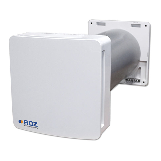
- Page 1 Air Handling Units Unità Trattamento Aria WHR 60 Mechanical ventilation with heat recovery appliance Ventilazione meccanica con sistema di recupero di calore TECHNICAL/INSTALLATION MANUAL MANUALE TECNICO/INSTALLAZIONE...
-
Page 3: Intended Use
INTRODUCTION This manual includes technical descriptions, installation instructions, assembly, maintenance and technical data exclusively directed to qualified personnel involved in the installation and maintenance of the product. INTENDED USE The product is artistically made and installed to allow a constant air exchange inside the room. The recovery system can be generally installed in residential or public places. - Page 4 CONTENT 1- Cosmetic Frontal Cover 7- Ceramic heat exchanger 2- Shutter 8- Filters 3- Unit 9- installing and maintenance manual 4i- Internal wall-mounting part with electrical 10- Precautions connections 11- RAEE warranty paper 4e- External wall-mounting part 12- Packaging 5- External conveyor 13- Warnings for proper unpackaging 6- Recessed duct 400mm...
-
Page 5: Technical Parameters
-20°C and 50°C with maximum relative humidity of 80%. The design of the Heat Recovery System is in continuous evolution, therefore, some models may differ from those described in this manual. DIMENSIONS, MM WHR 60 Speed Voltage at 50Hz 220-240Vac... -
Page 6: Installation
CONSTRUCTION The product is composed of a wall mounted unit to be placed inside the room, a recessed duct which contains the ceramic heat exchanger and filters and an external wall mounted conveyor. Ceramic heat conveyor External wall mounted conveyor Recessed duct External flter Internal filter... - Page 7 To install the product, the wall thickness cannot be less than 250mm. Once obtained the hole, put the recessed duct (6) into the wall. Make sure that the length of the recessed duct (6) is equal to the thickness of the wall. The duct must end with the internal and external surfaces of the wall.
- Page 8 Once adapted the length of the recessed duct (6) to the exact thickness of the wall, put the external wall- mounting part (4e) on the external wall as shown in the picture below: Insert the centering diameter of the wall- mounting part (4e) inside the recessed duct (6).
-
Page 9: Electrical Connections
Fix the external conveyor (5) on the external wall mounting part (4e) till the complete assembly, as shown in the pictures below: 2) ELECTRICAL CONNECTIONS Installation must only be carried out by qualified person. Make sure that the voltage of the installation room is in compliance with the value declared on the product label. - Page 10 Unlike the external wall mounting part, on the internal wall is necessary to bring the power supply conductors to connect them to the stripped wires supplied with the product. Provide an output for the wires, as the highlighted area shown in the picture Once the expansion plugs for the wall mounting are inserted, carefully check all the electrical operation before proceeding with the installation.
-
Page 11: Power Supply Connections
POWER SUPPLY CONNECTIONS Before proceeding with the connection, make sure that the wires (Live and Neutral) are inside the area specifically obtained in the wall. Take the internal wall-mounting part (4i) and the tools necessary to connect the main supply to the stripped wires supplied in the proper compartment. - Page 12 COMMUNICATION WITH SLAVE PRODUCTS If you consider to install one or more products in sequence to the main unit or make the connection in the future, refer to the pictures below to allow the communication between the master unit and the products in sequence It is recommended to use different cable colours to avoid to exchange the wiring connections.
- Page 13 3) ASSEMBLY CONCLUSION After the connection, carefully arrange the cables in the proper compartment and screw the internal wall-mounting part (4i) with the 4 screws as shown in the picture here below. Once fixed on the wall, insert the ceramic heat exchanger (7) with related filters (8), placing it in the middle of the recessed tube (6) as shown in the picture here below: Fix the main unit (3), with its shutter (2) and the cosmetic frontal cover (1) already assembled on it, on the internal wall-mounting part (4i) until complete assembly.
-
Page 14: Maintenance
MAINTENANCE All maintenance operations must only be done by qualified person. Before carrying out any cleaning or maintenance disconnect the main supply. Once installed, the product must have the components placed exactly as shown in the picture here above. 1) MAINTENANCE PERIOD INDICATIONS We recommend to clean the filters (8) and the ceramic exchanger (7) every 3 months. - Page 15 2) FILTERS AND EXCHANGER CLEANING OPERATIONS Pull out the main unit (1+2+3) from the wall using a flat screwdriver to drive the hook placed in the lower middle part of the product as shown in the pictures here below. Once the unit is unhooked from the internal wall-mounting part (4i) pull it out with the hands as shown in the picture below:...
- Page 16 Extract the ceramic heat exchanger together with the filters (8+7+8) by pulling the proper cord towards yourself as shown in the picture below. Remove the filters (8) from their location and clean them by using a vacuum cleaner or even washing them.
- Page 17 During the filters cleaning/replacement operations (8), remove any dirt residues in the ceramic heat exchanger by using a vacuum cleaner. DO NOT WASH UNDER WATER THE CERAMIC HEAT EXCHANGER. Once the cleaning operation has been completed, make sure to re-assemble the filters (8) in their location on the heat exchanger (7) by inserting the filters split under the rope as shown in the picture below:...
- Page 18 3)IMPELLER AND SHUTTER CLEANING Once the cleaning operation has been completed make sure to re-mount the filters and the heat exchanger in their location. Take the main unit group (1+2+3) and remove the cosmetic cover (1) by pulling out the upper hooks firstly and then the lower ones.
-
Page 19: Working Instructions
4) PRODUCT ASSEMBLY AFTER CLEANING Re-assemble the main unit (3) with the shutter (2) and cosmetic cover (1) on the wall-mounting (4i). ATTENTION: if different products are cleaned at the same time, re-mount every principal unit in the specific compartment from which they had been removed in order to avoid communication problems between Master unit and Slave unit. - Page 21 bit.ly/rdzwebsite...
Need help?
Do you have a question about the WHR 60 and is the answer not in the manual?
Questions and answers