Table of Contents
Advertisement
Quick Links
Advertisement
Table of Contents

Related Manuals for RDZ WHR 200


Summary of Contents for RDZ WHR 200
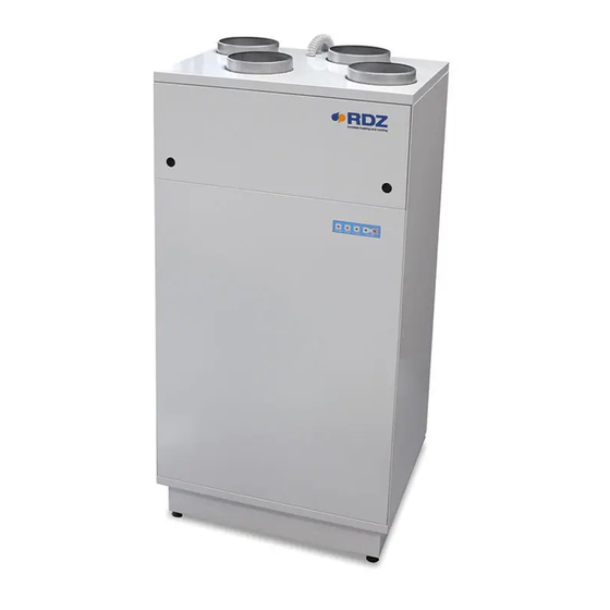
- Page 1 Air Handling Units Unità Trattamento Aria WHR 200 Controlled Mechanical Ventilation with heat recovery appliance Ventilazione Meccanica Controllata con sistema di recupero di calore TECHNICAL / INSTALLATION MANUAL MANUALE TECNICO / INSTALLAZIONE...
-
Page 3: Avvertenze Per La Sicurezza
SAFETY WARNINGS - AVVERTENZE PER LA SICUREZZA Read this manual carefully before installing and/or using the Le g g e re co n at te n z i o n e q u e s to l i b re t to p r i m a equipment and keep it in an accessible place. -
Page 4: Avvertenze Generali
• External wall grill for the ducts shall be installed according to • Per l’installazione delle bocchette e griglie esterne si the instructions and minimum spacing reported in this manual. raccomanda di rispettare le indicazioni di posizionamento e • Ducting should be insulated where it passes through unheated le distanze minime di rispetto riportate successivamente in spaces and voids (e.g. -
Page 5: Table Of Contents
PRELIMINARY OPERATIONS OPERAZIONI PRELIMINARI GENERAL OVERVIEW PANORAMICA GENERALE Description Descrizione Models And Accessories Modelli e Accessori WHR 200 Package Content Contenuto Imballo WHR 200 WHR 200 Components Componenti WHR 200 OVERVIEW OF THE SYSTEM PANORAMICA IMPIANTO INSTALLAZIONE INSTALLATION Duct Connections... -
Page 6: Operazioni Preliminari
PRELIMINARY OPERATIONS - OPERAZIONI PRELIMINARI TESTING, TRANSPORT AND UNPACKAGING ISPEZIONE, TRASPORTO E DISIMBALLO Upon receipt, check immediately that the packaging is intact: All’atto del ricevimento verificare immediatamente l’integrità the machine has left the factory in perfect working order and any dell’imballo: la macchina ha lasciato la fabbrica in perfetto stato, damage must be notified to the carrier immediately and noted on eventuali danni dovranno essere immediatamente contestati... -
Page 7: Panoramica Generale
WHR 200 contains two centrifugal fans, one supply fan and one La macchina presenta una struttura in lamiera post verniciata extract fan, provided with EC motor, operating at constant air bianca a tripla parete con isolamento termoacustico e flow and ensuring reduced energy consumption. -
Page 8: Descrizione
Cod. Control Panel 7045553 Control Panel Condensation drain kit 3600401 Kit scarico condensa PACKAGE CONTENT WHR 200 - CONTENUTO IMBALLO WHR 200 Cod. 7045552 Rif. Descriptions Descrizione WHR 200 WHR 200 Adhesive gasket for wall installation Guarnizione adesiva per installazione a parete... -
Page 9: Componenti Whr 200
WHR 200 COMPONENTS - COMPONENTI WHR 200 Cod. 7045552 Rif. Descriptions Descrizione Male Air Outlets Ø 150 mm Bocchette attacco M Ø 150 mm Air filter: G2 prefilter + M5 filter Filtri aria : Prefiltro G2 + Filtro M5 LED strip for operation / alarm signalling... -
Page 10: Panoramica Impianto
OVERVIEW OF THE SYSTEM - PANORAMICA IMPIANTO INSTALLATION EXAMPLE It is recommended to use a silencer in the supply duct. OUTSIDE ESTERNO ESEMPIO DI INSTALLAZIONE Si consiglia di prevedere un silenziatore sul canale di mandata agli ambienti INSIDE INTERNO... -
Page 11: Installazione
In addition, both ducts al fine di rispettare i regolamenti edilizi. connecting the WHR 200 to the outdoor air must be insulated when Usare sempre gli isolamenti sulle linee di Estrazione-Espulsione passing through heated areas to avoid condensation. - Page 12 Positioning indications & Minimum space allowances Indicazioni di posizionamento & Distanze minime di rispetto Exhaust Espulsione HORIZONTAL POSITIONING POSIZIONAMENTO ORIZZONTALE Inlet ≥ 60 cm Immissione Inlet Exhaust INSIDE OUTSIDE Immissione Espulsione INTERNO ESTERNO ≥ 60 cm Exhaust Exhaust Inlet Espulsione Immissione Espulsione VERTICAL POSITIONING...
- Page 13 Exhaust stale air to outside Extract stale air from rooms Inlet fresh air from outside Supply fresh air to rooms Espulsione aria viziata all’esterno Ripresa aria viziata dalle stanze Presa Aria fresca dall’esterno Immissione aria in ambiente Left-hand con guration - Con gurazione di sinistra Right-hand con guration - Con gurazione di destra Outside / Esterno Outside / Esterno...
-
Page 14: Posizionamento E Fissaggio
Since there is no need of free space on the two sides, WHR 200 tramite apposite staffe. can be mounted into 60-cm wide furniture (e.g. into a kitchen L’unità... - Page 15 Floor Installation Installazione a pavimento...
- Page 16 (*) No lateral constraint, also suitable for insertion into furniture (width not less than 60 cm) (*) Nessun vincolo laterale, adatta anche all’inserimento all’interno di mobilio (larghezza non inferiore ai 60 cm) Before mounting WHR 200 onto the wall, you shall install the 2 Prima di posizionare l’unità sulla parete è necessario applicare...
- Page 17 Ogni staffa di supporto ha un pre-foro per vite svasata. Diameter of the hole on the wall: Ø 10 [mm] Diametro foro su parete: Ø 10 [mm] WHR 200 weight: 62 Kg Peso WHR 200: 62 Kg Fixing to wall Fissaggio a muro Ø...
-
Page 18: Collegamenti Idraulici
(esempio verande esterne) per prevenire congelamento ADDITIONAL NOTES FOR RDZ DRAIN KIT INSTALLATION NOTE AGGIUNTIVE PER INSTALLAZIONE KIT SCARICO RDZ • Gently insert the syphon on the WHR exhaust pipe using the •... - Page 19 GENERAL INSTRUCTIONS INDICAZIONI GENERALI Discharge NOT in ascent angle! Scarico NON in salita! Make a siphon for each drain line Realizzare un sifone per ogni linea di scarico ≥3 cm 7 cm 4 cm Ø 14x20...
- Page 20 RDZ CONDENSATION DRAIN KIT KIT RDZ SCARICO CONDENSA CONDENSATION DRAIN KIT cod. 3600401 KIT SCARICO CONDENSA ≥3 cm...
-
Page 21: Collegamenti Elettrici
ELECTRICAL CONNECTIONS - COLLEGAMENTI ELETTRICI The Unit must be connected to a disconnected, earthed L’Unità deve essere collegata ad una presa di power socket. The electrical system must be protected against corrente sezionata provvista di terra. L’impianto elettrico di overloads, short circuits and direct and indirect contacts and alimentazione deve essere protetto contro i sovraccarichi, i comply with the laws and regulations in force in the country of cortocircuiti, i contatti diretti ed indiretti, conformemente... - Page 22 REMOVAL OF FRONT COVER RIMOZIONE PANNELLO FRONTALE Remove the 8 fixing screws from the front cover. Svitare le 8 viti di fissaggio del pannello frontale. Remove the cover. Rimuovere il pannello. POWER SUPPLY ALIMENTAZIONE Connect the 3 terminals with 3x1.5mm³ cable: Portare e collegare con cavo 3x1.5mmq i 3 morsetti: Phase (F) Fase (F)
-
Page 23: Configurazione E Comandi
COM V1 V2 V3 GND A DEHUM. REQUEST (DWF 200) RICHIESTA DEUM. (DWF 200) ECONOMY RENEWAL REQUEST RICHIESTA RINNOVO ECONOMY WHR 200 Control Panel serial card 1 COMFORT RENEWAL REQUEST RICHIESTA RINNOVO COMFORT BOOST REQUEST WI-SA Serie Design RICHIESTA BOOST... -
Page 24: Comandi Digitali E Parametri Di Funzionamento
DIGITAL CONTROLS AND OPERATION PARAMETERS COMANDI DIGITALI E PARAMETRI DI FUNZIONAMENTO DIGITAL INPUTS AND OUTPUTS INGRESSI E USCITE DIGITALI DIGITAL OUTPUT USCITA DIGITALE DWF 200 (max 5 A) DEHUMIDIFIER DEUMIDIFICATORE DIGITAL INPUT INGRESSI DIGITALI GND 24V SIGN DEHUMIDIFICATION REQUEST RICHIESTA DEUMIDIFICAZIONE ECONOMY RENEWAL REQUEST RICHIESTA RINNOVO ECONOMY COMFORT RENEWAL REQUEST... - Page 25 AIR FLOW SETTING FOR COMFORT VENTILATION IMPOSTAZIONE PORTATA ARIA RINNOVO COMFORT It is possible to set the flow rate of the fresh air ventilation in E’ possibile impostare la portata di Rinnovo Comfort modificando Comfort mode by changing the positions On/Off for the Switch 1 la posizione On/Off degli interruttori dello Switch 1 sulla scheda on the wiring board of the unit (default setting at 40 m /h) .
- Page 26 AIR FLOW SETTING FOR ECONOMONY VENTILATION IMPOSTAZIONE PORTATA ARIA RINNOVO ECONOMY It is possible to set the flow rate of the fresh air ventilation in E’ possibile impostare la portata di Rinnovo Economy Economy mode by changing the On/Off for 1-2-3 elements of the modificando la posizione On/Off degli interruttori 1-2-3 dello Switch 2 on the wiring board (default setting at 40 m /h) .
- Page 27 FREE COOLING TEMPERATURE SET SET TEMPERATURA FREE COOLING It is possible to set the temperature value for the automatic E’ possibile impostare un valore di temperatura per il operation of the Free Cooling mode by changing the position for funzionamento automatico della funzionalità di Free Cooling the jumper of the pin P20 on the wiring board of the unit (default modificando la posizione del jumper del pin P20 della scheda value at 25°C).
-
Page 28: Installazione Controllori Remoti
REMOTE CONTROLLER INSTALLATION - INSTALLAZIONE CONTROLLORI REMOTI CONNECTION TO THE CONTROL UNITS COLLEGAMENTI ALLE CENTRALINE DI COMANDO GND 24V SIGN SOLUZIONE “B” SOLUZIONE “A” WHR 200 Control Panel serial card 1 WI-SA Serie Design... - Page 29 MODBUS ADDRESS SETTING SETTAGGIO INDIRIZZO MODBUS SW 1 serial card 1 WHR 200 Control Panel WI-SA Serie Design SW 1 Unit 1 Unit 2 SW 1 SW 1 Unità 1 Unità 2 ON OFF ON OFF ON OFF...
-
Page 30: Funzionamento
FUNCTIONING - FUNZIONAMENTO FRESH AIR IN ECONOMY / COMFORT / BOOST MODE MODALITA’ RINNOVO ECONOMY / COMFORT / BOOST Exhaust stale air to outside Extract stale air from rooms Inlet fresh air from outside Supply fresh air to rooms Espulsione aria viziata all’esterno Ripresa aria viziata dalle stanze Presa Aria fresca dall’esterno Immissione aria in ambiente... - Page 31 DEHUMIDIFICATION AIR IN POST-TREATMENT (V3) DEUMIDIFICAZIONE ARIA IN POST-TRATTAMENTO (V3) If WHR 200 is combined with a room dehumidifier installed dowline Nel caso sia prevista una unità di deumidificazione ambiente of the heat recovery unit, you can use an external humidistat to a valle del recuperatore è...
- Page 32 FREE COOLING MODE MODALITA’ FREE COOLING Exhaust stale air to outside Extract stale air from rooms Inlet fresh air from outside Supply fresh air to rooms Espulsione aria viziata all’esterno Ripresa aria viziata dalle stanze Presa Aria fresca dall’esterno Immissione aria in ambiente Right-hand con guration - Con gurazione di destra Outside / Esterno Inlet-Supply Air Flow - Flusso Aria Ingresso-Immissione...
- Page 33 FREE-COOLING FREE-COOLING This unit is supplied with a motorized damper that can be Questo modello è fornito con una serranda motorizzata activated automatically or by means of a switch (*). attivabile automaticamente o tramite un interruttore (*). If Free-Cooling is ON, the fresh air from outside is not pre-heated Quando la funzionalità...
-
Page 34: Avviamento E Collaudo
START-UP AND TESTING - AVVIAMENTO E COLLAUDO UNIT STARTING - ACCENSIONE MACCHINA Before switching on the unit, make sure that wiring Prima di accendere la macchina, assicurarsi che connection has been carried out in the right way. tutti i collegamenti elettrici siano stati realizzati in maniera corretta. -
Page 35: Indicazioni Di Funzionamento
OPERATING INSTRUCTIONS - INDICAZIONI DI FUNZIONAMENTO The unit is provided with a LED stripe showing the connection and E’ presente a bordo dell’ unità una striscia led per le indicazioni operation status of the unit as well as the presence of any alarms sullo stato di collegamento e funzionamento, presenza and the necessary replacement of the filters with the corresponding eventuale di allarmi, segnalazione filtri sporchi e relativo... -
Page 36: Manutenzione Ordinaria
To clean or replace the filters, remove the protective covers located sostituiti. on the front of the unit. Contattare RDZ per l’acquisto dei nuovi filtri. After cleaning, install the filters and the detachable plates. Per pulire o sostituire i filtri, rimuovere i relativi coperchi di protezione situati sulla parte frontale dell’unità. - Page 37 every 90 days ogni 90 giorni...
-
Page 38: Pulizia Scambiatore Di Calore
RESET OF THE WARNING LIGHT OF THE DIRTY AIR FILTERS RESET ALLARME SPIA LED FILTRI ARIA SPORCHI Once the filter has been cleaned / replaced, reset the alarm using A pulizia/sostituzione filtro avvenuta, resettare l’allarme tramite the following procedure: la procedura seguente: Pressing the “R”... -
Page 40: Manutenzione Straordinaria
EXTRAORDINARY MAINTENANCE - MANUTENZIONE STRAORDINARIA All the extraordinary maintenance operations Tutte le operazioni di manutenzione straordinaria described in this chapter MUST ALWAYS BE CARRIED OUT BY descritte in questo capitolo DEVONO ESSERE SEMPRE QUALIFIED STAFF. ESEGUITE DA PERSONALE QUALIFICATO. REMOVING THE FAN RIMOZIONE VENTILATORE Warning! The fan replacement operations can be carried out after Attenzione! Le operazioni di sostituzione del ventilatore... -
Page 41: Dati Tecnici E Prestazioni
TECHNICAL DATA AND PERFORMANCE - DATI TECNICI E PRESTAZIONI DIMENSIONS - DIMENSIONI... -
Page 42: Prestazioni Secondo (Ue) N. 1254/2014
Reset allarme filtri tramite pulsante Led installato a bordo macchina r) not applicable r) Non applicabile s) Recycling disassembly instructions - see www.rdz.it s) Istruzioni per lo smaltimento -vai a www.rdz.it t) not applicable t) Non applicabile u) not applicable... - Page 43 v) Annual electricity consumption (AEC) (in kWh electricity/a) v) consumo annuo di elettricità (AEC) (in kWh di elettricità/a); Control typology and CTRL factor Tipo di controllo e fattore CTRL Manual Clock Central demand Local demand Manuale Temporizzato Ambientale centralizzato Ambientale locale 0.95 0.85 0.65...
-
Page 44: Etichetta Energetica
ENERGY LABEL - ETICHETTA ENERGETICA RDZ S.p.A. WHR 200 ENERGIA · · ΕΝΕΡΓΕΙΑ · ENERGIJA · ENERGY · ENERGIE 2016 FAK0CB004YZ.00 1254/2014... -
Page 45: Prestazione Ventilatori
FAN PERFORMANCE / PRESTAZIONI VENTILATORI Induct available pressure head 200 Pa Prevalenza utile disponibile alle bocchette 200 Pa at the maximum fresh air flow rate 250 m alla portata massima di rinnovo aria 250 m... -
Page 46: Schema Elettrico
10 WIRING DIAGRAM - SCHEMA ELETTRICO WHR 200 - Rev. 00 BLUE - BLU WHITE - BIANCO BLUE - BLU 0-10v PWM YELLOW - GIALLO YELLOW - GIALLO 0-10v PWM +10v OUT RED - ROSSO RED - ROSSO +10v OUT... - Page 48 FAG0CB003AB.00 05/2019...
Need help?
Do you have a question about the WHR 200 and is the answer not in the manual?
Questions and answers