
Related Manuals for Galaxy Control Systems 635 Series


Summary of Contents for Galaxy Control Systems 635 Series
- Page 1 SYSTEM GALAXY 635 & 600 HARDWARE INSTALLATION & CONFIGURATION SG v11.2.0 S28 11.0.3 Oct 2019...
- Page 2 System Galaxy 635-600 Series Hardware Manual Revised January 2019 635-600 Series Hardware Manual Rev. 11.1.0.2 ~ 2 ~...
- Page 3 Revision 11.1.0.2 or by any means, electronic or mechanical, for any purpose, without the express written consent of Galaxy Control Systems. Copyright protection claims include all forms and matters of copyrighted material and information, including but not limited to, material generated from the software programs, which are displayed on the screen such as icons, look and feel, etc.
-
Page 4: Table Of Contents
Table of Contents chapter-page Overview, Safeguards, Specifications, and Requirements What’s in this Manual (you are here) IMPORTANT: Product Safety and Precautions Hardware Certifications & Compliances Hardware Replacement Parts 1.4.1 ORDERING POWER TRANSFORMER & BATTERIES..................1-6 1.4.2 ORDERING REPLACEMENT BOARDS ......................1-6 Hardware Capability: Panel-Level (CPU) 1.5.1 Controller Capability of the 600/635 Model Access Control Panel: .............. - Page 5 1.14 Network & IT Requirements for Galaxy Hardware 1-29 1.15 Communication Requirements for System Galaxy Servers 1-30 1.16 Requirements for Logins and User Privileges (SG Software) 1-31 1.17 Pinout for Ethernet Cable (Cat-5e) 1-31 1.18 General FAQs about Features of Galaxy Hardware 1-32 Hardware Installation Instructions LIST OF TABLES IN THIS CHAPTER...
- Page 6 600-DIO - BOARD FEATURES 2-25 600-DIO – BOARD INSTALLATION 2-26 4.4 Installing a 635 DSI Board (Dual Serial Interface) ..................... 2-27 635-DSI - BOARD FEATURES 2-27 635-DSI - BOARD SPECIFICATIONS 2-28 THE 635-DSI SUPPORTED TECHNOLOGIES 2-28 635-DSI MAX NO. OF DEVICES & DEVICE COUNT (per Section) 2-29 635-DSI Examples of How DSI Sections Function Independently 2-30...
- Page 7 STEP 10. Wiring Field Devices to all Interface Boards 2-67 10.1 Field Wiring Standard Readers to the 635 DRM Board ................... 2-68 10.2 Field Wiring the SIGMA Morpho to the 635 DRM................... 2-70 10.3 Field Wiring the 635 DRM for ANTI PASSBACK ....................2-71 10.4 Field Wiring the DIO - Digital Input/Output board ..................
- Page 8 DSI port programming – Appendix: Resetting ODBC Connections B.1 : Configure your SG Data Sources – Appendix : View panel settings in Web Browser – Appendix : Checking Loop Programming – Appendix : Checking Controller Programming – Appendix : Starting & Stopping GCS Services –...
- Page 9 – Appendix: Replacing a 600 DPI with 635 DRM Q.1 Specifications for the 635 DPI Board INSTALL REQUIREMENTS ............................Q-2 Q.2 QUICK STEPS for installing a 635 DPI [STEP 1] FLASH / LOAD THE CPU ..........................Q-5 [STEP 2] FIND A VALID BOARD ID (via the software programming)................Q-6 [STEP 3] SET THE DPI DIPSWITCH (Board ID Addressing) ..................
- Page 10 Table 18: BINARY ADDRESS TABLE FOR 635-DRM 2-23 Table 19: DSI Max. Number of Devices and Device Count for each Section 2-29 Table 20: Examples of DSI Sections Functioning Independently 2-30 Table 21: Mapping the DSI “Section Use” in the SG Software 2-30 Table 22: SET THE TERMINATION JUMPERS FOR EACH SECTION 2-31...
- Page 11 Table of Figures: chap-page Figure 1 – 600/635 Model Controller (Access Control Panel) Basic 1-11 Figure 2 – CPU BOARD EDGE COMPONENTS: 635 CPU (Upper) & 600 CPU (Lower) 1-12 Figure 3 - Concept Diagram showing how Global Events use the GCS Event Service 1-15 Figure 4 - System Diagram of 600-series Loop/Clusters connecting to Event Server 1-16...
- Page 12 Figure 37 – Input Board Installation Options (Single Layer vs. Stacked) 2-47 Figure 38 – Input Board Component Designations and Connector Pinouts 2-48 Figure 39 – Input Board: Voltage-monitoring and Tamper-switch Wiring 2-48 Figure 40 – Input Board: Power Input Wiring 2-49 Figure 41 –...
- Page 13 page ~ x...
-
Page 14: What's In This Manual (You Are Here)
635/600-SERIES H ARDW ARE I NSTALL GUIDE 1 Overview, Safeguards, Specifications, and Requirements This chapter covers general safeguards and hardware requirements. Requirements are organized by topic (listed below) so that technicians, installers, planners, administrators and can easily find the pertinent information. What’s in this Manual (you are here) CHAPTER-1 OUTLINE What’s in this Manual (you are here) .............. -
Page 15: Table 1: Related Documents
635/600-SERIES H ARDW ARE I NSTALL GUIDE Appendixes as follows Appendix A ~ Hardware programming templates / tables that help installer and system owner record facts about the hardware configuration that will be used when setting up the software correctly. Appendix B ~ How to …... -
Page 16: Important: Product Safety And Precautions
635/600-SERIES H ARDW ARE I NSTALL GUIDE IMPORTANT: Product Safety and Precautions These notes apply to 635-model & 600-model Controllers (and their boards). Please read and follow. WARNING - Failure to obey safety warnings could result in serious bodily injury, death, and/or damage to equipment, and/or loss of data, and/or undesirable equipment/system operation. -
Page 17: Hardware Certifications & Compliances
635/600-SERIES H ARDW ARE I NSTALL GUIDE Hardware Certifications & Compliances The 600-Series & 635-Series Access Control Panel (ACP) is listed as follows: REGULATORY STANDARDS UL 294, Fifth Edition, Access Control System Units UL 1076, Fifth Edition, Proprietary Burglar Alarm Units and Systems ... - Page 18 635/600-SERIES H ARDW ARE I NSTALL GUIDE Power Supply (LifeSafety FPO75) for Controller (no transformer needed / for US or International): The LifeSafety FPO75 (75 Watt) Power Supply does not use a plug-in transformer. LifeSafety Power Supply is compatible for international installations. CAUTION: Power Input Jumper (JP1) is set 120 VAC/ 60 HZ (Factory Default;...
-
Page 19: Hardware Replacement Parts
635/600-SERIES H ARDW ARE I NSTALL GUIDE Hardware Replacement Parts The 600-series and 635-series Access Control Panels use the following replacement parts: 1.4.1 ORDERING POWER TRANSFORMER & BATTERIES +3V Lithium Battery – Panasonic CR2354 • Galaxy PN 53-2035-00 • Installs on-board, for the 600-CPU, 635-CPU. -
Page 20: Hardware Capability: Panel-Level (Cpu)
635/600-SERIES H ARDW ARE I NSTALL GUIDE Hardware Capability: Panel-Level (CPU) 1.5.1 Controller Capability of the 600/635 Model Access Control Panel: TCP/IP (CPU on-board) Ethernet Network Communication: • 635 MODEL CPU = 10/100 MB / Full Duplex Auto-sensing Ethernet Network capable (600 Model CPU = 10MB Full Duplex Ethernet Network capable) •... -
Page 21: Hardware Capability: Board-Level
635/600-SERIES H ARDW ARE I NSTALL GUIDE Hardware Capability: Board-Level 1.6.1 List of Boards and Component Descriptions: This is the list of CPU & Daughter Boards as of System Galaxy v10 Software. 1. CPU Board (600 model & 635 model ) - Central Processing Unit Supports up to 64 Devices (readers, inputs, etc.) per CPU board/panel ... - Page 22 635/600-SERIES H ARDW ARE I NSTALL GUIDE 3. 600 DIO Board - Digital Input / Output Board– Supports maximum 8 inputs per board Supports maximum 4 outputs per board SW1 Reset Switch 4. DSI Board - Dual Serial Port Interface – 2 RS485 Communication Ports per board (Section-1/Section-2) ...
-
Page 23: Hardware & System Descriptions
635/600-SERIES H ARDW ARE I NSTALL GUIDE Hardware & System Descriptions 1.7.1 Description of Galaxy Access Control Panel: ENCLOSURE DIMENSIONS: ELECTRICAL CABINET, HINGED • GAUGE • 8-DOOR/MEDIUM = 18 13.75 6.25 in. ADDITIONAL PANEL SIZES OFFERED: • 2-DOOR/SMALL = 12 4 in. -
Page 24: Figure 1 – 600/635 Model Controller (Access Control Panel) Basic
635/600-SERIES H ARDW ARE I NSTALL GUIDE Figure 1 – 600/635 Model Controller (Access Control Panel) Basic Chapter-Page 1-11... -
Page 25: 635/600-Series Cpu Description
635/600-SERIES H ARDW ARE I NSTALL GUIDE 1.7.2 635/600-series CPU Description: See Appendix M for complete list of CPU components The CPU Board is the brains of the controller and holds the S28 Flash Code in its memory. 635 CPUs are compatible with all 635 and 600 series daughter boards. •... -
Page 26: 635/600 Drm (Dpi) Description
635/600-SERIES H ARDW ARE I NSTALL GUIDE 1.7.3 635/600 DRM (DPI) Description: See Appendix M for complete component list of 600 DPI The DRM (DPI) Board controls the readers, door contacts, request to exit, door lock, and offers an additional output relay for both reader/door ports. 600 and 635 DPI’s are interchangeably compatible with either a 635 or 600-series CPU. -
Page 27: Dsi Description
635/600-SERIES H ARDW ARE I NSTALL GUIDE 1.7.5 600 DSI Description: See Appendix M for complete component list of 600 DSI The DSI Board controls two (2) RS-485 serial ports per board for the following devices: PERIPHERALS Cypress Clock (Time Clock model 1201) ... -
Page 28: The System Described
635/600-SERIES H ARDW ARE I NSTALL GUIDE 1.7.7 The System Described: The hardware side of the system includes controllers (panels) and all field hardware (readers, locks, REXs, etc.) that make up the access control system. The panels interoperate with the System Galaxy Software by sending event messages over a LAN/WAN network to the Event Server (i.e. -
Page 29: Sg System Diagram - Communication/Event Server
635/600-SERIES H ARDW ARE I NSTALL GUIDE 1.7.8 SG System Diagram – Communication/Event Server: In the diagram (below) you can see how the GCS Services are connected and transmit messages to the System Galaxy Database and to the System Galaxy Software/Monitoring screen. -
Page 30: Sg System Planning Notes
635/600-SERIES H ARDW ARE I NSTALL GUIDE 1.7.9 SG System Planning Notes: While the installer can begin installing the Galaxy Hardware before the software and database are installed, keep in mind that the SG Database & Communication Server (software/database &GCS services) must be installed before the panels can connect to the system and be walk-tested. -
Page 31: Cpu & Board Flash Requirements For 600/635-Series Hardware
635/600-SERIES H ARDW ARE I NSTALL GUIDE CPU & Board Flash Requirements for 600/635-Series Hardware 1.8.1 About Factory Flash and Field-Flashing the CPU: CPU boards come with a pre-installed, factory flash code. Factory flash allows the boards to start up (boot up) and be configured before they have been field-flashed. This lets the installer configure network parameters and other settings. -
Page 32: About Auto-Updating The Daughter Boards
635/600-SERIES H ARDW ARE I NSTALL GUIDE 1.8.2 About Auto-Updating the Daughter Boards: Daughter boards come with a pre-installed factory version of flash code that allows the boards to boot up even though they have not been field-flashed. • All daughter boards (DPI, DRM, DIO, DSI) must be running the correct field flash. •... - Page 33 635/600-SERIES H ARDW ARE I NSTALL GUIDE Table 6: BOARD COMPATIBILITY CHART for SG 10/11 Tables 7 & 8 for SG-9 or lower WHEN IS UPGRADING SG SOFTWARE REQUIRED ?… if an SG version is noted, then that is the minimum version of SG required to support that board/feature ...
-
Page 34: Table 7: Flash Version Chart For Sg-9 (And Older)
635/600-SERIES H ARDW ARE I NSTALL GUIDE 1.8.2 Older Flash Version Compatibility Charts (SG-9 / SG-8): Table 7: FLASH VERSION CHART for SG-9 (and older) FLASH VERSION SOFTWARE VERSION V4.57 Flash SG 9.0.5 4.57 4.57 4.57 4.57 V4.51 Flash 4.51 4.51 4.51... -
Page 35: Controller Mounting Requirements
635/600-SERIES H ARDW ARE I NSTALL GUIDE Controller Mounting Requirements The controller enclosure must be wall mounted using tear-drop shaped mounting holes. Panel can be mounted horizontally (typical) or vertically Non-condensable: do not mount in or near water, liquid, moisture or rain/weather ... -
Page 36: Figure 6 – 6Xx-Series Medium Controller Dimensions & Knockout Diagram:
635/600-SERIES H ARDW ARE I NSTALL GUIDE Figure 6 – 6xx-series Medium Controller Dimensions & Knockout Diagram: This diagram shows a facing (inside) view of the back and inside views of sides for a medium controller enclosure. Drawing is shown rotated 90 degrees to fit on page. Dimensions shown in inches. -
Page 37: Power Requirements
635/600-SERIES H ARDW ARE I NSTALL GUIDE 1.10 Power Requirements A Power Transformer 16VAC @ 40 VA (transformer included if purchased with panels). • Power transformer must be plugged into a 110VAC/60Hz outlet that is less than 25 feet from the controller. -
Page 38: Relay Ratings And Current Draw
635/600-SERIES H ARDW ARE I NSTALL GUIDE 1.11 Relay Ratings and Current Draw The following tables show Relay Ratings and the Current Draw with and without relays energized. Table 9: Ratings for Relays for Galaxy Hardware Board Relay Type Port Output = 635 DRM Reader Board Form-C SPDT Relays 24 VDC @ 1.5 amps maximum per relay. -
Page 39: Hardware Wiring Specifications
635/600-SERIES H ARDW ARE I NSTALL GUIDE 1.12 Hardware Wiring Specifications 1.12.1 Controller Ethernet Communications: 635 CPU = Auto-sensing 10/100 Mb /Full Duplex at the port side. 600 CPU = 10 Mb Ethernet/Full Duplex at the port side. 1.12.2 Hardware Wiring Specifications (Type, Gauge, Distance): Table 11: DEVICE WIRING SPECIFICATIONS Connection Type... -
Page 40: Board Programming Requirements
635/600-SERIES H ARDW ARE I NSTALL GUIDE 1.13 Board Programming Requirements 1. 635- model boards can be configured using the Galaxy 635 Web Configuration Tool. The 635 Web Tool opens in a standard Web Browser. The Tool automatically finds all Galaxy CPUs by their MAC address, provided the panels are online/on the same network segment as the Web Tool –... -
Page 41: Figure 7 – 600/635-Model Controller Configuration Example:
635/600-SERIES H ARDW ARE I NSTALL GUIDE Figure 7 – 600/635-Model Controller Configuration Example: This example shows of how the Controllers/CPUs are grouped into Loop/Clusters and configured connect to the System Galaxy Event Service using the TCP/IP Ethernet network ( Every 600/635-Model Controller (CPU) is assigned a unique/valid Loop/Cluster ID (i.e. -
Page 42: Network & It Requirements For Galaxy Hardware
635/600-SERIES H ARDW ARE I NSTALL GUIDE 1.14 Network & IT Requirements for Galaxy Hardware This section lists requirements that pertain to System Environment, Networking and IT Requirements. Galaxy Hardware is designed to communicate over TCP/IP connections/networks with the following stipulations. 1. -
Page 43: Communication Requirements For System Galaxy Servers
635/600-SERIES H ARDW ARE I NSTALL GUIDE 1.15 Communication Requirements for System Galaxy Servers This section covers info about System Galaxy services, which affect logging events from the hardware. EVENT HANDLING (MONITORING VS. LOGGING EVENTS) 1. When the SG Software is installed, typically the core GCS Services are installed on the same machine (GCS Client Gateway Service, GCS Communication Service, GCS Event Service, GCS DB Writer Service). -
Page 44: Requirements For Logins And User Privileges (Sg Software)
635/600-SERIES H ARDW ARE I NSTALL GUIDE 1.16 Requirements for Logins and User Privileges (SG Software) 1. You must have Administrator Rights In order to install System Galaxy Software. 2. Operator/User must log in as a’ power user’ in order to program hardware in the System Galaxy software. 3. -
Page 45: General Faqs About Features Of Galaxy Hardware
635/600-SERIES H ARDW ARE I NSTALL GUIDE 1.18 General FAQs about Features of Galaxy Hardware System Galaxy 10 software allows both 508i Loops and 635/600 Loops at the same site; however the 508i and 600 panels cannot be mixed into the same loop. ... -
Page 46: Hardware Installation Instructions
635-SERIES H ARDWARE M ANU AL 2. Hardware Installation Instructions IMPORTANT: Each STEP of the install instructions should be performed in sequence. Each step is dependent upon the previous step. Each step must be completed correctly. Skipping steps or doing steps out of sequence will result in an improper installation and system failure. -
Page 47: List Of Tables In This Chapter
635-SERIES H ARDWARE M ANU AL 6.1 Programming the 635-Model CPU Board via Web Page ............2-55 STEP 7. Set the Interface Board ID’s (DPI/DIO/DSI) ..........2-60 7.1 Apply power to the “Daughter” Boards (DPI/DIO/DSI) ............2-60 7.2 Verify Board ID is Correct for Daughter Board(s) (DRM/DIO/DSI) ........2-61 7.3 Verify Flash Version is Correct for Daughter Board(s) (DRM/DIO/DSI) ...... -
Page 48: List Of Figures Found In This Chapter
635-SERIES H ARDWARE M ANU AL Table 22: SET THE TERMINATION JUMPERS FOR EACH SECTION ..............2-31 Table 23: SET THE PASS-THRU JUMPERS FOR EACH SECTION ..............2-32 Table 24: BINARY ADDRESS TABLE FOR 635-DRM .................... 2-33 Table 25: BINARY ADDRESS TABLE FOR OUTPUT RELAY BOARD ..............2-38 Table 26: WIRING PINOUT FROM 635-DSI TO FIRST RELAY BOARD ............... - Page 49 635-SERIES H ARDWARE M ANU AL Figure 36 – Example of Single Layer vs. Stacked Install (SEE PART 4.6.3 FOR EXACT INSTRUCTIONS) ..2-45 Figure 37 – Input Board Installation Options (Single Layer vs. Stacked) ............2-47 Figure 38 – Input Board Component Designations and Connector Pinouts ............. 2-48 Figure 39 –...
-
Page 50: Step 1. Hardware Install ~ Site Preparation
635-SERIES H ARDWARE M ANU AL STEP 1. Hardware Install ~ Site Preparation Site Preparation varies for every customer, and the installation chapter is concerned with providing requirements and standards for planning and installing the hardware. 1.1 Conducting a Site Survey Conduct a site survey to ensure you know exactly how much and which pieces of hardware you need to install. -
Page 51: Figure 8 – Illustration Of Ul-Listed Power Supply And Transformer
635-SERIES H ARDWARE M ANU AL Controller Class-2, Plug-in AC Transformer: The AC transformer, used in Galaxy’s UL-listed controller, is a Class-2, plug-in type transformer with fused secondary. The transformer is UL-listed and CSA Certified and can be plugged into a duplex plug. The transformer should be Input-rated 120 VAC/49 VA at 60 Hz;... -
Page 52: Requirements And Safeguards
635-SERIES H ARDWARE M ANU AL 1.2 Requirements and Safeguards You must follow all safeguards and requirements when installing Galaxy hardware. SAFEGUARDS: These notes apply to 635-model & 600-model Controllers (and their boards). Please read and follow. WARNING - Failure to obey safety warnings could result in serious bodily injury, death, and/or damage to equipment, and/or loss of data, and/or undesirable equipment/system operation. -
Page 53: Table 13: Wiring Specifications
635-SERIES H ARDWARE M ANU AL REQUIREMENTS: These notes apply to 635-model & 600-model Controllers (and their boards). Please read and follow. 1. Controller Power Source: System Galaxy Controller requires a continuous power source from a 110VAC non- switchable outlet* 2. -
Page 54: About Upgrading Hardware / Expanding Systems
635-SERIES H ARDWARE M ANU AL 1.3 About Upgrading Hardware / Expanding Systems If you are installing new hardware on an existing system, these are considerations you must make. WHEN IS UPGRADING THE HARDWARE REQUIRED? Installing Wireless Readers, IP Readers? – you must upgrade to 635 CPU and 635-DSI ... -
Page 55: Table 14: Board Compatibility Chart For Sg10
635-SERIES H ARDWARE M ANU AL 1.4 Board Compatibility and Capability (635 vs. 600 models) The table below shows the compatibility of Galaxy boards and features when using SG 10.X software. NOTES ABOUT REPAIR / MAINTENANCE / UPGRADE OF 600-MODEL CONTROLLERS BOARDS ARE SWAPPABLE! You can replace old 600-model CPU, DPI, OR DSI with a new 635-model board and maintain existing functionality in your hardware and software configuration. -
Page 56: Step 2. Mount The Controller Enclosure/Cabinet
635-SERIES H ARDWARE M ANU AL STEP 2. Mount the Controller Enclosure/Cabinet 2.1 Choose a good location for the Controller Choose a proper location for the controller: Obey wiring distances, preplan the locations for your controllers and all hardware devices (readers, inputs, etc.). See Chapter 1, power, current draw and wiring requirements. -
Page 57: Running Field Wiring
635-SERIES H ARDWARE M ANU AL 2.2 Running Field Wiring Typically, most of the field wiring is run before the controller/hardware is installed. Route wiring in a neat and secure manner. Do NOT run data wires near high power/high frequency devices or wiring. Leave a service loop inside the controller for future maintenance. -
Page 58: Mount The Controller Cabinet
635-SERIES H ARDWARE M ANU AL 2.3 Mount the Controller Cabinet Mount the 6xx-series cabinet with the door swinging down. (Cabinet can optionally be mounted with door swinging to the left.) The overall size of the medium controller cabinet is 18” W x 13 ¾” H x 6 ¼” D. ... -
Page 59: Step 3. Install Power Connectors Inside Controller
635-SERIES H ARDWARE M ANU AL STEP 3. Install Power Connectors inside Controller Step-3 is about wiring the two-piece orange connectors to the wiring harness inside the panel. WARNING: DO NOT short the power wires together. Failure to properly insulate wires could result in damage to the equipment or electrical shocks. -
Page 60: Table 15: 635-Cpu Pinout
635-SERIES H ARDWARE M ANU AL 3.2 Wire the CPU Power Connector and Tamper Switch CAUTION: UNPLUG CONTROLLER FROM POWER OUTLET. Do not attempt to wire the connectors while the power supply is “hot”. Wiring a controller while it is “hot” can cause electrical shock, serious injury, death, damage to equipment, or system failure. -
Page 61: Wire The "A/C Fail" And "Low Battery" To Sense Connector
635-SERIES H ARDWARE M ANU AL 3.3 Wire the “A/C Fail” and “Low Battery” to Sense Connector CAUTION: UNPLUG CONTROLLER FROM POWER OUTLET. Do not attempt to wire connectors while the power supply is “hot”. Wiring a connector while it is “hot” can cause electrical shock, serious injury, death, damage to equipment, or system failure. -
Page 62: Wire The Power Connectors For The Boards (Drm, Dio, Or Dsi)
635-SERIES H ARDWARE M ANU AL 3.4 Wire the Power Connectors for the Boards (DRM, DIO, or DSI) CAUTION: UNPLUG CONTROLLER FROM POWER OUTLET. Do not attempt to wire connectors while the power supply is “hot”. Wiring a connector while it is “hot” can cause electrical shock, serious injury, death, damage to equipment, or system failure. -
Page 63: Step 4.
635-SERIES H ARDWARE M ANU AL STEP 4. Install the CPU and Interface Boards (daughter boards) IMPORTANT: DO NOT CONNECT CONTROLLER TO POWER DURING FIRST-TIME INSTALLATION STEPS. IF YOU ARE REPLACING A BOARD ON EXISTING SYSTEM, KEEP IT DISCONNECTED FROM THE POWER HARNESS WHILE YOU ARE HANDLING THE BOARD OR WIRING/CONNECTING OTHER DEVICES. -
Page 64: Installing A 635-Drm Board (Dual Reader Module)
635-SERIES H ARDWARE M ANU AL 4.2 Installing a 635-DRM Board (Dual Reader Module) If you are not installing a DRM board, skip this section. If you are installing the 635-DRM for Remote Door operation, see the section for 635-DSI Remote Door installation. 635-DRM - BOARD FEATURES For reference, this section describes the components and features of the 635-DRM. -
Page 65: Drm - Install Requirements
635-SERIES H ARDWARE M ANU AL 635-DRM - INSTALL REQUIREMENTS CAUTION: do not reset power to a DRM during the flashing process. This can damage the factory flash. WARNING: Do Not Connect A 5V Reader Directly to the 635 DRM – you must install a voltage regulator for 5V readers or configure the reader for 12V. -
Page 66: Drm – Board Installation (Standard Operation)
635-SERIES H ARDWARE M ANU AL 635-DRM – BOARD INSTALLATION (STANDARD OPERATION) If you are installing the 635-DRM for Remote Door operation, see the section for 635-DSI Remote Door installation. This section covers installing the DRM board as a standard daughter board on the I2C Buss (i.e. not as a Remote Door Module on the RS-485 Channel). -
Page 67: Table 16: Dry-Contact Relay Operation = (Normal Operation)
635-SERIES H ARDWARE M ANU AL PART 4.2.2 SETTING THE LOCK RELAY JUMPERS If you are using Dry-Contact Relay Operation (factory default) then the black jumpers are removed (not installed). 2) ABOUT SETTING THE RELAY JUMPERS: Relay-1: The contact jumpers affect only the Lock Relay (R1) •... -
Page 68: Table 18: Binary Address Table For 635-Drm
635-SERIES H ARDWARE M ANU AL PART 4.2.3 (REQUIRED) PRE-CONFIGURING THE BOARD ID 3) SETTING THE BOARD ID (SW2): a) The Binary Dipswitch [SW2] is located on the center-back edge of the DRM board. • Each board ID must be unique (no duplicates) and valid (1 thru 16). •... -
Page 69: Part 4.2.4 (Required) Installing The 635 Drm Board In The Controller
635-SERIES H ARDWARE M ANU AL PART 4.2.4 (REQUIRED) INSTALLING THE 635 DRM BOARD IN THE CONTROLLER If you are not installing a DRM on the I2C Buss, skip this section. If you are installing a DRM as a “Remote Door Module”... -
Page 70: Install The Dio Board In The Controller
635-SERIES H ARDWARE M ANU AL 4.3 Install the DIO Board in the Controller If you are not installing a DIO board, skip this section. The DIO board is a 600-model board (there is not a 635 version of this board). 600-DIO - BOARD FEATURES ... -
Page 71: Dio – Board Installation
635-SERIES H ARDWARE M ANU AL 600-DIO – BOARD INSTALLATION If you are not installing a DIO board, then skip this section. The DIO board is a 600-model board (there is not a 635 version of this board). 1. Loosen the stand-offs and mount Board (bracket) flush against the back wall of cabinet, in next available slot. DO NOT mount bracket on end of stand-off –... -
Page 72: Installing A 635 Dsi Board (Dual Serial Interface)
635-SERIES H ARDWARE M ANU AL 4.4 Installing a 635 DSI Board (Dual Serial Interface) If you are not installing a 635-DSI board, skip this section. 635-DSI - BOARD FEATURES This section covers the 635-model DSI Board. See the Appendix for the 600-model DSI Features. ... -
Page 73: Dsi - Board Specifications
635-SERIES H ARDWARE M ANU AL 635-DSI - BOARD SPECIFICATIONS The 635 DSI Board has two (2) RS-485 Serial ports (sections J6/J5). 1. Each RS-485 Section supports a max 16 devices in most cases (i.e. DRM readers, WiFi readers(PIMS), clocks, LCDs, ...). -
Page 74: Table 19: Dsi Max. Number Of Devices And Device Count For Each Section
635-SERIES H ARDWARE M ANU AL 635-DSI MAX NO. OF DEVICES & DEVICE COUNT (per Section) Table 19: DSI Max. Number of Devices and Device Count for each Section Use of section Hardware Devices* per Section Valid IDs Device Count Remote Readers 635-CPU Max. -
Page 75: Table 20: Examples Of Dsi Sections Functioning Independently
635-SERIES H ARDWARE M ANU AL 635-DSI Examples of How DSI Sections Function Independently This table clarifies how the sections can work independently. You don’t have to put the same hardware on one section as you do on the other section. However, you do have to stay under the 64-device max CPU count. Table 20: Examples of DSI Sections Functioning Independently Functions 635-DSI SECTION-1... -
Page 76: Table 22: Set The Termination Jumpers For Each Section
635-SERIES H ARDWARE M ANU AL 635-DSI – BOARD INSTALLATION If you are not installing a DSI board, then skip this section. This section covers the 635-model board. The 600 version of this board is covered in an older manual, but as far as mounting the board into the cabinet, the steps are the same. -
Page 77: Table 23: Set The Pass-Thru Jumpers For Each Section
635-SERIES H ARDWARE M ANU AL PART 4.4.2 SETTING THE PASS-THRU VOLTAGE JUMPERS If you are not using pass-thru voltage and the jumpers (JP1/JP2) are already in the UNSET, then skip this part. For convenience, the 635 DSI supports Pass-thru voltage from the power input. The voltage (12v/24v) is passed thru Pin-4 (Pwr Out) of the RS-485 Connectors (J6/J5). -
Page 78: Table 24: Binary Address Table For 635-Drm
635-SERIES H ARDWARE M ANU AL PART 4.4.3 ( ) PRE-CONFIGURING THE BOARD ID REQUIRED SETTING THE BOARD ID (SW2): a) The Binary Dipswitch [SW2] is located on the center of the DSI board. • Each board ID must be unique (no duplicates) and valid (1 thru 16). •... -
Page 79: Figure 24 – Installing A Dsi Board With Bracket Against Back Of Cabinet:
635-SERIES H ARDWARE M ANU AL PART 4.2 4 ( ) INSTALLING THE 635 DSI BOARD IN THE CONTROLLER REQUIRED IF You are not installing a DSI, skip this section 1. Loosen the stand-offs and mount Board (bracket) flush against the back wall of cabinet, in next available slot. DO NOT mount bracket on end of stand-off –... -
Page 80: Installing A 635-Model Output Relay Board
635-SERIES H ARDWARE M ANU AL 4.5 Installing a 635-Model Output Relay Board If you are not installing a Relay Board, skip this section. Notice: if you are upgrading a 500-model ORM, this is the solution you will use. NOTICE: The Relay Board can install in a single layer in the cabinet, or you can use a stacking kit which is available from the Galaxy Product Catalog. -
Page 81: Relay Board – Installation Of Board In Controller
635-SERIES H ARDWARE M ANU AL 635-RELAY BOARD – INSTALLATION OF BOARD IN CONTROLLER If you are not installing a Relay Board, then skip this section. PART 4.5.1 PREP STEPS - BEFORE INSTALLING THE RELAY BOARDS You must know how many boards will be on each DSI 485 Channel (Section). The use (i.e. general output or elevator control) will determine how many boards you can support on a DSI Section. -
Page 82: Figure 27 – Example Of Relay Boards Installed In A Separate Panel
635-SERIES H ARDWARE M ANU AL Figure 27 – Example of Relay Boards Installed in a Separate Panel This diagram shows the Relay Boards installed in a second (auxiliary) panel. All control boards must be in the Main Panel. SEE PART 4.5.3 FOR CORRECT INSTALL INSTRUCTIONS. The additional panels will hold . -
Page 83: Table 25: Binary Address Table For Output Relay Board
635-SERIES H ARDWARE M ANU AL PART 4.5.2 CONFIGURE THE RELAY BOARD IDs ( REQUIRED • You can do this as you install each board – but do not forget to do it. • If you are stacking the boards, you must address the lower boards before you install the upper board. 2. -
Page 84: Figure 29 – Relay Board Installation Options (Single Layer Vs. Stacked)
635-SERIES H ARDWARE M ANU AL PART 4.5.3 INSTALLING THE BOARDS IN THE PANELS ( REQUIRED 3. INSTALLING BOARDS IN A SINGLE LAYER ONLY: << SKIP THIS STEP IF YOU ARE STACKING >> a. Make sure you have set the Board Numbers to the appropriate, unique IDs (via binary dipswitch). b. -
Page 85: Figure 30 – 635-Relay Board: Wiring The Relay Terminals
635-SERIES H ARDWARE M ANU AL WIRING THE RELAYS (NO vs. NC): a. The relays are Dry Form-C SPDT Rated at 24v 1.5 Amps. b. You can wire the relays Normally Open (NO) or Normally Closed (NC), as needed. Figure 30 – 635-Relay Board: Wiring the Relay Terminals Diagram shows where to land wires for Relay Terminals. -
Page 86: Figure 32 – Relay Board Installation (On The 635-Dsi Board's Rs-485 Multidrop)
635-SERIES H ARDWARE M ANU AL 8. WIRING THE RS-485 MULTI-DROP: Diagram shows Boards installed on the DSI Board Section-1 in a multidrop (daisy chain) configuration. DO NOT USE A STAR CONFIGURATION ON THE 485 SECTION SEE NEXT PAGE FOR RS485 PINOUT GUIDE Figure 32 –... -
Page 87: Table 26: Wiring Pinout From 635-Dsi To First Relay Board
635-SERIES H ARDWARE M ANU AL Drawing is not to scale. STEP-8 PINOUT GUIDE FOR RS-485 MULTIDROP • Relay Boards must be installed in a multidrop (daisy chain) configuration. • DO NOT USE A “STAR” CONFIGURATION ON THE RS485 SECTION. Table 26: WIRING PINOUT FROM 635-DSI TO FIRST RELAY BOARD DSI BOARD RS-485 (J5 / J6) FIRST RELAY BOARD RS-485 ON MULTIDROP... -
Page 88: Installing 635-Model Input Module
635-SERIES H ARDWARE M ANU AL 4.6 Installing 635-Model Input Module If you are not installing a 635 Input Board, skip this section. NOTICE: If you are upgrading older 500-series Controllers with 500 AMMs, this is the solution you will use. NOTICE: The Input Boards can be installed in a single layer (1 Input Board on 4 studs), or you can use a stacking kit - available from the Galaxy Product Catalog. -
Page 89: Input Module – Installation Of Boards In Controller Panels
635-SERIES H ARDWARE M ANU AL 635-INPUT MODULE – INSTALLATION OF BOARDS IN CONTROLLER PANELS If you are not installing an Input Board, then skip this section. PART 4.6.1 PREP STEPS - BEFORE INSTALLING THE INPUT BOARDS 1. You must know how many boards will be on each DSI 485 Channel (Section). The last Input Board on the RS485-Section must be within the 4,000 ft. -
Page 90: Figure 35 – Basic Example Of Input Boards Installed In A Separate Panel
635-SERIES H ARDWARE M ANU AL Figure 35 – Basic Example of Input Boards Installed in a Separate Panel This diagram shows the Input Boards installed in the second (auxiliary) panel. The CPU, DSI are in the Main Panel. 2. You must decide how the boards will be installed in the electrical cabinets. a. -
Page 91: Table 28: Binary Dipswitch Settings For Input Board
635-SERIES H ARDWARE M ANU AL PART 4.6.2 CONFIGURE THE BOARD IDs ( REQUIRED • You can do this as you install each board – but do not forget to do it. • If you are stacking the boards, you must address the lower boards before you install the upper board. 3. -
Page 92: Figure 37 – Input Board Installation Options (Single Layer Vs. Stacked)
635-SERIES H ARDWARE M ANU AL PART 4.6.3 INSTALLING THE BOARDS IN THE PANELS ( REQUIRED 4. INSTALLING BOARDS IN A SINGLE LAYER ONLY: << SKIP THIS STEP IF YOU ARE STACKING >> a. Make sure you have set the Board Numbers to the appropriate IDs. b. -
Page 93: Figure 38 – Input Board Component Designations And Connector Pinouts
635-SERIES H ARDWARE M ANU AL WIRING THE INPUTS: Wire the inputs to the pluggable/ interlocking, 2-way 2-pin TB Connectors. The pluggable/interlocking 2-pin connectors are arranged into four banks of connectors. You can unplug each one from the board for ease of wiring (but be careful to observe the polarity of your wiring. NOTICE: These are 2-way TBC connectors, which means …. -
Page 94: Figure 40 – Input Board: Power Input Wiring
635-SERIES H ARDWARE M ANU AL WIRING THE POWER INPUT CONNECTOR: Remove the Orange 2-Piece Connector and wire it as follows: Connect the Ground wire to the side marked with the ground symbol • • Connect power to the side marked 12v Figure 40 –... - Page 95 635-SERIES H ARDWARE M ANU AL 10. WIRING THE RS-485 MULTI-DROP: Diagram shows Boards installed on 635-DSI Board Section-1 in a multidrop (daisy chain) configuration. DO NOT USE A STAR CONFIGURATION ON THE 485 SECTION SEE NEXT PAGE FOR RS485 PINOUT GUIDE Figure 41 –...
-
Page 96: Table 29: Wiring Pinout From The 635-Dsi To First Input Board
635-SERIES H ARDWARE M ANU AL STEP-10 PINOUT GUIDE FOR RS-485 MULTIDROP • Boards must be installed in a multidrop (daisy chain) configuration. • DO NOT USE A “STAR” CONFIGURATION ON THE RS-485 SECTION. Table 29: WIRING PINOUT FROM THE 635-DSI TO FIRST INPUT BOARD DSI BOARD RS-485 (J5 / J6) FIRST INPUT BOARD RS-485 ON MULTIDROP A (pin 1) -
Page 97: Step 5. Applying Power To The Controller
635-SERIES H ARDWARE M ANU AL STEP 5. Applying Power to the Controller 5.1 Pull all field wiring into the controller Pull all the field wiring into the controller cabinet, using conduit and the supplied knock-outs taking care to not pinch or strain wiring. Leave enough extra wire to make a service loop. -
Page 98: About Adding An Auxiliary Power Supply Inside The Controller
635-SERIES H ARDWARE M ANU AL 5.3 About adding an Auxiliary Power Supply inside the Controller The controller has room and mounting studs for a second power supply, if needed to support proximity readers, Relay Boards, Input Boards, etc. For the standard 8-door controller, if there are more than four (4) proximity readers attached to the controller, you may need two SMP3 Power Supplies. -
Page 99: Step 6. Program The 635 Cpu Board
635-SERIES H ARDWARE M ANU AL STEP 6. Program the 635 CPU Board Configuring the CPU Board can be done from a Web Browser via the Embedded Web Page. Using the Configuration Tool will allow you to find the controllers by their MAC address as long as the door is open (tamper switch open) and they are on the same network segment as your PC/Laptop. -
Page 100: Programming The 635-Model Cpu Board Via Web Page
635-SERIES H ARDWARE M ANU AL 6.1 Programming the 635-Model CPU Board via Web Page This subsection provides quick steps for programming the CPU from the embedded web page. The CPU comes from the factory with a default 192 … IP Address. You can identify each CPU by its serial number. SEE CHAPTER-1 FOR A FULL LIST OF IT REQUIREMENTS •... -
Page 101: Figure 44 – Example Of 'All Panel Summary' Screen – List Of Detected Panels
635-SERIES H ARDWARE M ANU AL 4. The Config Tool automatically detects all 635 CPU’s by MAC address on the same network segment if the CPU’s web enable option is ON (factory default) AND the cabinet door is open (tamper switch). You must use Putty or HyperTerminal if the web-enable option is turned off. -
Page 102: Figure 45 – Example Of 'Network Configuration' Screen – Cpu Network Settings
635-SERIES H ARDWARE M ANU AL 5. From All Panels Summary page, click on the CPU Serial Number to open Network Configuration screen. This screen allows you to view the current network settings and to give the 635 Panel a descriptive name (location) and configure the network settings. -
Page 103: Figure 46 – Example Of 'Panel Status' Screen – (Cpu Status / Current Settings)
635-SERIES H ARDWARE M ANU AL 6. From the All Panels Summary page, click on the CPU IP Address to open the Panel Status screen – see below. 7. On the Panel Status screen you must click the Panel Configuration link – at the bottom of the screen. This screen displays the CPU’s current settings and connection status to the Event Server, as well as useful statistics such as flash version, number of users (cards), unacknowledged logs, and date/time (real-time). -
Page 104: Figure 47 – Example Of 'Panel Configuration' Screen – ( Cpu Programming )
635-SERIES H ARDWARE M ANU AL 8. From the Panel Status screen, click on the Panel Configuration link (at the bottom of the screen) to open the Panel Configuration screen. • UPDATE button – sends (posts) your changes to the panel (CPU). •... -
Page 105: Step 7. Set The Interface Board Id's (Dpi/Dio/Dsi)
635-SERIES H ARDWARE M ANU AL STEP 7. Set the Interface Board ID’s (DPI/DIO/DSI) This step covers powering up, connecting to the data buss and setting the board ID for the daughter Boards (i.e. DPI, DIO, DSI, etc.) IMPORTANT: BEST PRACTICE is to bring one board on at a time. 7.1 Apply power to the “Daughter”... -
Page 106: Verify Board Id Is Correct For Daughter Board(S) (Drm/Dio/Dsi)
635-SERIES H ARDWARE M ANU AL 7.2 Verify Board ID is Correct for Daughter Board(s) (DRM/DIO/DSI) From the Web Browser, press F5 and you should see the daughter board come online on the Panel Status page. VERIFY THE BOARD # is unique and set correctly, as expected. Figure 48 –... -
Page 107: Flash Version Chart
635-SERIES H ARDWARE M ANU AL 7.4 Flash Version Chart The CPU and Daughter Board Flash version must be the correct version for System Galaxy software. CAUTION: If downgrading a CPU to Flash v5.00 or older, disconnect daughter boards before flashing CPU. Table 31: FLASH VERSION CHART S28 FLASH VERSION SOFTWARE VERSION... -
Page 108: Step 8. Connect The Controller Cpu To The Network
635-SERIES H ARDWARE M ANU AL STEP 8. Connect the Controller CPU to the Network PC to Controller Communications: 600 CPU uses TCP/IP 10 Mb Ethernet/Full Duplex at the port side. 635 CPU uses TCP/IP 100 Mb Ethernet/Full Duplex at the port side. DISTANCE from the Controller to the switch: conform to TCP/IP specifications (max 300 ft from Controller to switch;... -
Page 109: Verify Connection To The Event Server
635-SERIES H ARDWARE M ANU AL 8.2 Verify Connection to the Event Server 1. Verify the controller is connected to the Event Server by opening the GCS Event Service and finding the controller IP Address in the list of Controller Connections tab. You should see the controller’s IP Address showing connected status. - Page 110 635-SERIES H ARDWARE M ANU AL Figure 50 – Controller’s Embedded Web Report: Example of Type your panel’s static address in the browser address field (ex: http://198.168.0.1). You must be on the same network segment to be able to get the panel’s Embedded Web Page. Chapter-Page 2-65...
-
Page 111: Step 9. Test The Controller (Recommended)
635-SERIES H ARDWARE M ANU AL STEP 9. Test the Controller (recommended) Galaxy recommends that you test the Galaxy hardware before landing field wiring: Testing the hardware proves the panels are installed and configured correctly. If it is not feasible to do at this time, proceed to the next step for wiring field devices. -
Page 112: Table 32: Wiring Distances For Hardware
635-SERIES H ARDWARE M ANU AL STEP 10. Wiring Field Devices to all Interface Boards This section covers field wiring (readers, locks, rex, outputs, etc.) to the interface boards (DIO, DRM, DSI, etc). Always leave a “service loop” or slack in the panel when wiring the field devices. This ensures there is •... -
Page 113: Field Wiring Standard Readers To The 635 Drm Board
635-SERIES H ARDWARE M ANU AL 10.1 Field Wiring Standard Readers to the 635 DRM Board NOTE: Always follow the silk-screened marks on the back of the board you are wiring ! NOTICE: If you are installing MORE than FOUR (4) Proximity Readers, you should use an additional power supply for the additional readers. -
Page 114: Figure 52 – Drm Board: Reader Wiring Template – For Typical Reader Technologies
635-SERIES H ARDWARE M ANU AL Figure 52 – DRM BOARD: Reader Wiring Template – for typical reader technologies. Diagram shows how wiring looks from the front (terminal screw) side of the connectors. Chapter-Page 2-69... -
Page 115: Field Wiring The Sigma Morpho To The 635 Drm
635-SERIES H ARDWARE M ANU AL 10.2 Field Wiring the SIGMA Morpho to the 635 DRM 3. IF you are installing a Morpho SIGMA Reader – use the following diagram. Figure 53 – DRM board: Reader Wiring Template for the SIGMA Reader. Diagram shows how wiring looks from the front (terminal screw) side of the connectors. -
Page 116: Field Wiring The 635 Drm For Anti Passback
635-SERIES H ARDWARE M ANU AL 10.3 Field Wiring the 635 DRM for ANTI PASSBACK 4. IF you are wiring readers for Anti-Passback, use the following steps and diagram. You can use Sections 1 and 2 on the same DPI board or you can use two Sections on separate boards, but they should be in the same controller enclosure. -
Page 117: Field Wiring The Dio - Digital Input/Output Board
635-SERIES H ARDWARE M ANU AL 10.4 Field Wiring the DIO - Digital Input/Output board This STEP covers DIO Rev C and D. Remove the 2-piece orange connectors and land wiring as indicated in the diagram. J1, J2, J3 and J4 are used for wiring up to eight (8) possible inputs. Pin 2 on all ... -
Page 118: About Setting Up Supervision & Hypervision Of Inputs
635-SERIES H ARDWARE M ANU AL 10.5 About setting up Supervision & Hypervision of Inputs Supervision & Hypervision modes are programmable Built-in features of the DIO Board and are enabled at the software in the Input Programming Screen after supervision resisters have been installed at the device. -
Page 119: Hypervision Of Inputs:
635-SERIES H ARDWARE M ANU AL HYPERVISION OF INPUTS: Hypervision is a new feature that provides an added layer of security that protects supervised inputs from being defeated. Hypervision uses alternating voltages and additional thresholds for the supervised input. Supervision resistors must be installed and setup before Hypervision can be enabled. The DIO board applies two different, alternating source voltages to the input circuit. -
Page 120: Field Wiring The 635-Input Modules To The 635-Dsi Board
635-SERIES H ARDWARE M ANU AL 10.6 Field Wiring the 635-Input Modules to the 635-DSI Board Figure 57 – Wiring the 635-Input Board to a 635-DSI Board: The DSI BOARD is shown component-side up (typically it installs component-side down) – keep this in mind when you are landing wires. -
Page 121: Field Wiring Output Relay Boards To The 635-Dsi Board
635-SERIES H ARDWARE M ANU AL 10.7 Field Wiring Output Relay Boards to the 635-DSI Board Figure 58 – Wiring a 600-Relay Board to a 635-DSI Board: The DSI BOARD is shown component-side up (typically it installs component-side down) – keep this in mind when you are landing wires. -
Page 122: Field Wiring Schlage Ad Pims To The 635-Dsi Board
635-SERIES H ARDWARE M ANU AL 10.7 Field Wiring Schlage AD PIMs to the 635-DSI Board Figure 59 – Wiring a Schlage AD PIM to a 635-DSI Board: The DSI BOARD is shown component-side up (typically it installs component-side down) – keep this in mind when you are landing wires. -
Page 123: Field Wiring 635-Drm Remote Door Module To The 635 Dsi Multidrop
635-SERIES H ARDWARE M ANU AL 10.8 Field Wiring 635-DRM Remote Door Module to the 635 DSI Multidrop Figure 60 – Wiring a 635-DRM (for Remote Door Modules) to a 635-DSI Board: The DSI BOARD is shown component-side up (typically, it installs component-side down) – keep this in mind when you are landing wires. -
Page 124: Field Wiring Cypress Clock To 635-Dsi Board
635-SERIES H ARDWARE M ANU AL 10.9 Field Wiring Cypress Clock to 635-DSI Board Remove the 2-piece orange connectors and land wiring as indicated in the diagram. There are 2 RS-485 Sections(ports) – each section is independent (for example you can ... -
Page 125: Field Wiring Lcd Display Unit To 635-Dsi Board
635-SERIES H ARDWARE M ANU AL 10.10 Field Wiring LCD Display Unit to 635-DSI Board - SET UNIT IDs: YOU MUST USE THE Galaxy Configuration Programming Tool to configure the Display UNIT IDs (1 thru 16 are valid). The DSI supports 16 max. units per 485 Section. Remove the back cover of the Display Module and insert the wiring through the opening provided in the back cover. -
Page 126: Table 33: Software Setup - Process For 600 Loops Are As Follows
635-SERIES H ARDWARE M ANU AL STEP 11. Walk-Test the System (recommended) If you have not set up the minimal software programming required to walk-test the system, you can turn to Step 9 and reference the Software Setup Quick Notes. 11.1 Quick Steps to Software Setup More in-depth programming information is found the main SG Software Manual. -
Page 127: Quick Steps To Creating A Test Card
635-SERIES H ARDWARE M ANU AL 11.2 Quick Steps to creating a Test Card Once you have completed the Loading of a loop, it is a good idea to create a “test card”. Create test cards in the Cardholder Programming Screen. It is recommended you test access. When creating the test cards do the following: 1. -
Page 128: Communication /Event Server Overview
600-SERIES HARDWARE MANUAL Event Server Overview 3 Communication /Event Server Overview This chapter covers the Galaxy Communication and Event Server and its role in the Hardware system. Use this chapter for troubleshooting or to understand how the Event Server works. 3.1 Description of the Communication Server Core GCS Services and usually the System Galaxy software run on the Communication Server. -
Page 129: Ip Connections Between Services
600-SERIES HARDWARE MANUAL Event Server Overview 3.2 IP Connections between Services Figure 29 - Block Diagram of core GCS Services: Chapter-Page 3-2... -
Page 130: Opening The Gcs Event Service Window:
600-SERIES HARDWARE MANUAL Event Server Overview 3.3 Opening the GCS Event Service window: right-click the icon found on the system tray and select ‘Open’ 3.4 Managing the 600 Controller Connections: The 600 Controller Connections tab displays the names and status of each 600-series controller that is connected to the Event Service. -
Page 131: Managing The Tcp/Ip Service Connections:
600-SERIES HARDWARE MANUAL Event Server Overview 3.5 Managing the TCP/IP Service Connections: The TCP/IP Service Connections tab displays the name of the incoming connection from the GCS Comm Service including the DNS name of the PC the Comm Service is running on. Also this screen shows the IP Address and Security Protocol of the incoming connection. -
Page 132: About The Status Of Connections:
600-SERIES HARDWARE MANUAL Event Server Overview 3.6 About the Status of Connections: The Status Messages tab displays a buffer of status messages for the 600 Panels attempting to connect to the Event Server/Service. In this example, two 600-series panels have successfully connected to the Event Server. The 600-series panels are designed to initiate their connection to the Event Server. -
Page 133: Configuring The Controller Connection Settings:
600-SERIES HARDWARE MANUAL Event Server Overview 3.7 Configuring the Controller Connection Settings: Open this window by selecting Setup then Configure, from the menu bar. The controller connection port should be set to ‘3001’ and click APPLY to save. Figure 33 - Event Service Settings >... -
Page 134: Configuring The Tcp/Ip Client Server Settings:
600-SERIES HARDWARE MANUAL Event Server Overview 3.8 Configuring the TCP/IP Client Server Settings: The Incoming Connections Port should be set to ‘4003’ and press APPLY to save (see Appendix D for Software Loop properties screen) Figure 34 - Event Service Settings > TCP/IP Client Server Settings screen: Incoming Connections - The GCS Comm Server makes an incoming connection to the Event Server. -
Page 135: Configuring The Odbc Settings:
600-SERIES HARDWARE MANUAL Event Server Overview 3.9 Configuring the ODBC Settings: Beginning in SG-9 the Event Service maintains an ODBC connection to SysGal database. Click the TEST CONNECTION button to verify that your Event Service can connect to the database successfully. -
Page 136: Hardware Troubleshooting
600-SERIES HARDWARE MANUAL Trouble Shooting 4 Hardware Troubleshooting This chapter covers troubleshooting information for System Galaxy. The following sections are included: HARDWARE TROUBLESHOOTING SECTIONS: Section 4.1 : Troubleshooting Connectivity and Red-X on Loops Section 4.2 : Verifying connections between services Section 4.3 : Verifying settings in the SG Properties Screen Section 4.4 :... -
Page 137: Troubleshooting Connectivity And Red-X On Loops
600-SERIES HARDWARE MANUAL Trouble Shooting 4.1 Troubleshooting Connectivity and Red-X on Loops This part covers troubleshooting Controller Connectivity and Red-X on Loops. The Software and Services initiate connections in a “daisy-chain” fashion to each other. Part 3.2 of this chapter contains troubleshooting tips for services; also see the diagram provided in this chapter, section 3.3. -
Page 138: Verifying Connections Between Services
600-SERIES HARDWARE MANUAL Trouble Shooting 4.2 Verifying connections between Services It is possible to have a red-X on the hardware tree if the IP connections between SG and/or any of services are not established or panel programming does not match the system programming: NOTE: a diagram showing the connectivity between the Software, Services and Panels is shown in Section 3.3. - Page 139 600-SERIES HARDWARE MANUAL Trouble Shooting System Galaxy application: a) Has an outgoing connection to the Gateway service. If the Red-X is on the Communication Control Window between SG and the Gateway, user can force a connect with the button at the bottom of the Communication Control Window.
- Page 140 600-SERIES HARDWARE MANUAL Trouble Shooting Verify that port blocking/firewall software is setup to accept the following ports 3001, 4003, 4002, 4001, 4000, 5010 as appropriate at each computer running System Galaxy services. Chapter 1 Sections 1.8 through 1.10 have consolidated requirements for Networks.
-
Page 141: Verifying Settings In Sg Properties Screens
600-SERIES HARDWARE MANUAL Trouble Shooting 4.3 Verifying settings in SG Properties Screens It is possible to have a Red-X on the hardware tree because the Loop and/or Controller Properties screen are not correct. Also see Figure 32 for an picture of how the software programming must match the programming at the panel. -
Page 142: Verifying Settings At The Controller (Cpu)
600-SERIES HARDWARE MANUAL Trouble Shooting 4.4 Verifying settings at the Controller (CPU) It is the responsibility of the Panel to initiate the connection to the Event Server/Service. NOTE: a diagram showing the connectivity between the Software, Services and Panels is shown in Section 3.3. -
Page 143: Figure 36 - Programming At The Software Must Match The Controller:
600-SERIES HARDWARE MANUAL Trouble Shooting Figure 36 - Programming at the Software must match the Controller: Chapter-Page 4-8... -
Page 144: A – Appendix : Programming Templates
600-SERIES HARDWARE MANUAL Appendix A - Programming Templates A – Appendix : Programming Templates Use templates to ensure hardware settings are unique and can be programmed to match the software. A.1 DPI - Reader port programming Sample: in the example there are 3 DPI boards with Section 2 on DPI 2 is unused Cluster ID Unit CPU #... -
Page 145: A.2 Dio Port Programming
600-SERIES HARDWARE MANUAL Appendix A - Programming Templates A.2 DIO port programming Template can be copied as needed. INPUT OUTPUT SAMPLE DIO ID Cluster ID Unit ID CPU # Port # / Use Port # / Use 1, 2, 3, 4 / MD 1 = SIREN 5 / TIMER 2 = LIGHT CONTROL... - Page 146 600-SERIES HARDWARE MANUAL Appendix A - Programming Templates A.3 DSI port programming Template can be copied as needed. Cluster ID Unit CPU # Section 1 Section 2 DSI ID (Loop) 232 OR 485 Port / Use 232 OR 485 Port / Use APPENDIX-Page A-3...
- Page 147 600-SERIES HARDWARE MANUAL Appendix B - Connecting to the ODBC Data Source B – Appendix: Resetting ODBC Connections The Core GCS services must maintain ODBC connections to the System Galaxy database to support live man-readable messaging and other features. B.1 : Configure your SG Data Sources Open the ODBC Data Source Administrator in the GCS Service you need to configure ( you can open the Service from the System Tray ) ...
- Page 148 600-SERIES HARDWARE MANUAL Appendix B - Connecting to the ODBC Data Source Configure your Data Sources (continued) Supply the login & password to your database Click [ NEXT ] to continue NOTE: the options to use SQL Server Authentication and to Connect to SQL Server… should be used unless the system owner has chosen to use Integrated Windows Login. APPENDIX-Page B-2...
- Page 149 600-SERIES HARDWARE MANUAL Appendix B - Connecting to the ODBC Data Source Configure your Data Sources (continued) Select the Database Name Click [ Next ] to continue NOTE: SysGal is the default database name. However, this name can be customized by the system owner during or after the SG Database server is installed. Ensure you see/select the correct database name for in this field. SUPPORT: If you do not know the database name, contact the owner or IT / DB Administrator to determine which database name should be used and resolve any issues with permissions. If you cannot see the expected database name in the list, contact the IT Administrator to resolve network issues ( ). i.e. ports, firewalls, etc. ...
- Page 150 600-SERIES HARDWARE MANUAL Appendix B - Connecting to the ODBC Data Source Configure your Data Sources (continued) use default settings Click the FINISH button to continue Click the TEST DATA SOURCE button to verify ODBC connectivity APPENDIX-Page B-4...
- Page 151 600-SERIES HARDWARE MANUAL Appendix B - Connecting to the ODBC Data Source Configure your Data Sources (continued) Confirm that the test is SUCCESSFUL Click the OK button to continue APPENDIX-Page B-5...
- Page 152 600-SERIES HARDWARE MANUAL Appendix B - Connecting to the ODBC Data Source Click the OK button to complete the DSN configuration APPENDIX-Page B-6...
- Page 153 600-SERIES HARDWARE MANUAL Appendix C - View controller settings from Web Browser – Appendix : View panel settings in Web Browser To view the panel settings from a Web Browser, open a Web Browser from the server. In the Browser’s address field, type the IP Address of the controller you want to see. ...
- Page 154 600-SERIES HARDWARE MANUAL Appendix D - Checking Loop Programming in Software D – Appendix : Checking Loop Programming To verify the Loop/Cluster is correctly programmed into the SG Software, you must look in the Loop Properties screen in the System Galaxy software. ...
- Page 155 600-SERIES HARDWARE MANUAL Appendix E - Checking Controller Programming in Software E – Appendix : Checking Controller Programming To verify the Controller is correctly programmed into the SG Software, you must look in the Controller Properties screen in the System Galaxy software. Note: to edit fields in the software you must click the EDIT button.
- Page 156 600-SERIES HARDWARE MANUAL Appendix F - Starting and Stopping Services F – Appendix : Starting & Stopping GCS Services The core GCS Services must be running and have their listening ports correctly set to log events to the SG Software and Database. Ports must be unblocked at firewalls and devices. Listening Core Service Name Ports...
- Page 157 600-SERIES HARDWARE MANUAL Appendix G - Opening the Event Service G – Appendix : Opening the Event Service The GCS Event Service will display every controller that is programmed to connect to it. The controller will initiate the connection to the Event Service. The Event Service should be set to run automatically when the Event Server/PC is started.
- Page 158 600-SERIES HARDWARE MANUAL Appendix H - HyperTerminal Commands H – Appendix : Putty/HyperTerminal Commands A. Connecting to a Terminal Emulator Connect the programming serial cable to the J4 serial port of the CPU Board (Rev H or later) and the standard 9-pin serial (com) port on the PC or laptop that will run Terminal Emulator. A programming cable comes with the controller enclosure: •...
- Page 159 600-SERIES HARDWARE MANUAL Appendix H - HyperTerminal Commands When you have the Terminal Session established you will use the following commands to perform your work. Commands Description / Use All commands are typed in lowercase. install Default login /password to the panel (set at factory) This can be changed in the panel’s config mode and must match the software.
- Page 160 600-SERIES HARDWARE MANUAL Appendix H - HyperTerminal Commands B. Programming the CPU Board (Reference Chapter 1 for a consolidated list of IT Requirements). IMPORTANT: See the Network Administrator to obtain network parameters. You must use unique and valid ID’s when programming a CPU. Logging into Board’s Config Mode: IMPORTANT: You MUST type the all entries in lowercase...
- Page 161 600-SERIES HARDWARE MANUAL Appendix H - HyperTerminal Commands Selecting the CPU Board to Edit: When prompted to enter a board number, you will type “0” and press <Enter> key. The current configuration will display, with the prompt “Do you wish to make changes? (yes/no)” : if this is a new board from the factory, you will see factory test settings in it.
- Page 162 600-SERIES HARDWARE MANUAL Appendix H - HyperTerminal Commands Setting the IP Address and Network Parameters: NOTICE: Addressing must be set correctly or the board will not work. See Network Administrator to get a valid IP Address, Network Mask and Gateway Address. Set the IP Address and press <Enter>...
- Page 163 600-SERIES HARDWARE MANUAL Appendix H - HyperTerminal Commands Setting the Loop and Controller ID’s: Use templates found in Appendix -A to record hardware configurations. Copy as needed, Set Cluster/Loop ID: this value must be “1” (one) or greater. All CPU’s in the same cluster/ loop will have the same Loop ID. ...
- Page 164 600-SERIES HARDWARE MANUAL Appendix H - HyperTerminal Commands Setting Passwords and Encryption fields (optional): TIP: If you want to keep the factory default settings, you can press the <Enter> key to skip through these fields – options are explained below. Setting a PASSWORD: (optional) used only for telnet;...
- Page 165 600-SERIES HARDWARE MANUAL Appendix H - HyperTerminal Commands Allow Web Server: this allows technician to view the configuration from a Web Browser. Note: You cannot change the panel configuration from the web browser. Use DHCP Server: this option determines if the CPU board will obtain an IP Address dynamically.
- Page 166 600-SERIES HARDWARE MANUAL Appendix H - HyperTerminal Commands The ‘Save Confirmation’: when you leave the last programming field, HyperTerminal will re-display your new configuration and will show the prompt “save new settings yes or no?” at the bottom of the screen. b) Type “yes”...
- Page 167 600-SERIES HARDWARE MANUAL Appendix H - HyperTerminal Commands C. Configuring the Board ID for 600-model Daughter Boards (DPI/DIO/DSI) 635 NOTICE – 635 uses a binary dipswitch to set the Board ID and auto-update feature. See Appendix-Q for instructions. At the HyperTerminal ‘>’ prompt, type “config” and press the <Enter> key. A list of boards is displayed: The board you are currently programming should be listed Board 33.
- Page 168 600-SERIES HARDWARE MANUAL Appendix H - HyperTerminal Commands VERIFY BOARD IDS From HyperTerminal – issue a boards command. Note: as firmware advances, the current flash code version will change. The data layout may also be different from one version to another. The image below is using v4.60 s28. 10.
- Page 169 600-SERIES HARDWARE MANUAL Appendix I - How to find IP Address of Event Server – Appendix : Finding IP Address of Event Server Go to the computer that runs the GCS Event Service. Open a DOS Command Window and execute the ipconfig command at the prompt: To open a DOS shell: 1.
- Page 170 600-SERIES HARDWARE MANUAL Appendix J - Pinging Controller from Server J – Appendix : Ping Controller from Event Server To ping a controller from the Event Server, open a DOS command prompt as shown: To open a DOS shell: 1.
- Page 171 600-SERIES HARDWARE MANUAL DPI Emergency Release Wiring K – Appendix : Wiring DPI Emergency Release The DPI boards can be wired to use and Emergency Release Device to unlock doors. This feature is only available to the “local” boards within the same controller. You cannot trigger lock releases on DPI boards in separate cans.
- Page 172 600-SERIES HARDWARE MANUAL Appendix L - List of Terms L – Appendix : List of Terms 600-series 600-series is the model name for the Galaxy hardware equipment (controller, circuit boards, etc.). 600-series boards are not interchangeable with other Galaxy models. 600 hardware is supported in SG 8.1 or later.
- Page 173 600-SERIES HARDWARE MANUAL Appendix L - List of Terms Firewall A software application that blocks or allows certain ports according to how it is programmed or set up. System Galaxy uses 5010, 4000, 4001, 4002, 4003, 1433 Flash The act of loading flash code to the controller CPU; or the code itself. GCS Client Gateway GCS Client Gateway Service is a System Galaxy background service that handles service...
- Page 174 600-SERIES HARDWARE MANUAL Appendix L - List of Terms HyperTerminal® A Microsoft® communication program that can be used to change the configuration or to troubleshoot the 600-series controller boards. IE® Microsoft® Internet Explorer® web browser, which can be used to view and verify the controller configuration over IP connection.
-
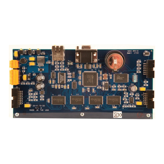
Page 175: M – Appendix: 635 & 600 Series Boards M
600-SERIES HARDWARE MANUAL Appendix M - 635-600 Series Boards M – Appendix: 635 & 600 Series Boards M.1 635 CPU Board – Central Process Unit Component List [SW 1] Power Reset Switch - power reset /warmstart (press and hold full 10 seconds to coldstart) [J4] DB9 Serial Port: used for programming the board via HyperTerminal session [J5] Ethernet Jack: for TCP/IP 100Mb/Full Duplex [J6] Power Connector: CPU power, CPU Board draws 0.05 amps... - Page 176 600-SERIES HARDWARE MANUAL Appendix M - 635-600 Series Boards M.2 600 CPU Board – Central Process Unit Component List [J1] Config Jack (if jack plug is installed at the time of power reset, board is coldstarted) [J3] Spare Jack (use this to park the jack plug after coldstart is performed) [SW 1] Power Reset Switch - power reset depends on position of J1 jack-plug [J2] Factory Programming Port - not used in field [J4] DB9 Serial Port: used for programming the board via HyperTerminal session...
- Page 177 600-SERIES HARDWARE MANUAL Appendix M - 635-600 Series Boards M.3 600 DPI Reader Board - Dual Port Interface Board [J1] Config Jack (when jack plug is installed at the time of power reset, board is in Config mode) [SW 1] Power Reset Switch - power reset [J3] Reader Voltage Jumper (Port 2/Section 2): used to set +5 volts or +12 volts for the reader [J4] Relay 2 (Port 2/Section 2): wiring contacts for auxiliary Relay 2 [D1] Relay 2 LED (Port 2/Section 2): is lit/ON when the Relay 2 is energized...
- Page 178 600-SERIES HARDWARE MANUAL Appendix M - 635-600 Series Boards M.4 DIO Board – Digital Input/Output Board Component List [J1 - J4] Inputs 1 through 8: terminal connectors for wiring eight (8) maximum inputs to the DIO board [D1 - D4] Input Relay LED’s: indicate (ON/lit) when relays energize. [J5 - J8] Output Relays (4) terminal connectors for wiring outputs to the DIO board (uses form C relays);...
- Page 179 600-SERIES HARDWARE MANUAL Appendix M - 635-600 Series Boards M.5 DSI Board– Dual Serial Interface board Component List: [J1] I2C Data Buss: port to connect to the data ribbon cable. [SW 1] Power Reset Switch - power reset [J2] Config Jack: (when jack plug is installed at the time of power reset, board is in Config mode) [J3] Factory Port: factory use [J4] Power connector: +12 VDC board power connects from the wiring harness [J5] RS-232 port for Section 2: wiring contacts for an RS-232 channel (future release)
- Page 180 600-SERIES HARDWARE MANUAL Appendix M - 635-600 Series Boards M.6 Relay board (General Output or Elevator Control) Each Relay Board has eight (8) Form-A SPST output relays. The Relay board should be powered separate from CPU & DSI. Relay boards are used in General Output panels or Elevator Control panels. See the following section on the type of panel you are installing for configuration specs and wiring.
-
Page 181: N – Appendix : 600 Relay Panels
600-SERIES HARDWARE MANUAL Appendix N - 600 Relay Panels N – Appendix : 600 Relay Panels N.1 General Output Relay Panel (First Panel) The first panel will need a CPU and DSI-Serial board. The unused studs can be used to mount a relay board (4 studs per relay board, which takes up 2 slots in the panel). -
Page 182: N.2 General Output Relay Panel (Second Panel)
600-SERIES HARDWARE MANUAL Appendix N - 600 Relay Panels N.2 General Output Relay Panel (Second Panel) The additional panels only house relay boards. Three (3) boards max. in a short cabinet; six (6) boards max. in a long cabinet. The relay boards in this panel are wired back to the first panel. NOTE: If the relay board in a second/additional panel is daisy-chained to a relay board, it will use the next sequential board ID in that chain (i.e. -
Page 183: N.3 Elevator Control Panel (First Panel )
600-SERIES HARDWARE MANUAL Appendix N - 600 Relay Panels N.3 Elevator Control Panel (First Panel ) The first panel will need a CPU, DPI-Reader board & DSI-Serial board. The unused studs can be used to mount a relay board (4 studs per relay board, which takes up 2 slots in the panel). Relay boards in 1 panel require separate 2.5 amp power. -
Page 184: N.4 Elevator Control Panel (Second/Additional Panel)
600-SERIES HARDWARE MANUAL Appendix N - 600 Relay Panels N.4 Elevator Control Panel (Second/Additional Panel) The additional panels only house relay boards. Three (3) boards max. in a short can. Six (6) boards max. in a long can. The relay boards in this panel are wired back to the first panel. NOTE: If the relay board in a second/additional panel is daisy-chained to a relay board, it will use the next sequential Board ID in that chain (i.e. -
Page 185: O – Appendix : Output Relay Board Help
600-SERIES HARDWARE MANUAL Appendix O - Output Relay Board Help O – Appendix : Output Relay Board Help O.1 Relay board (General Output or Elevator Control) Each Relay Board has eight (8) Form-A SPST output relays. The Relay board should be powered separate from CPU & DSI. Relay boards are used in General Output panels or Elevator Control panels. -
Page 186: O.2 Relay Board Power And Data Wiring
600-SERIES HARDWARE MANUAL Appendix O - Output Relay Board Help O.2 Relay Board Power and Data Wiring NOTE: one board draws 0.02 a (20 mA); and if all 8 relays energized at the same time, the board draws a max of 0.6 a (600 ma). POWER WIRING in the 1st panel: Relay boards are NOT wired to the same power supply as the CPU, DPI and DSI boards. -
Page 187: O.3 Relay Board Dipswitch Settings For Board Numbers
600-SERIES HARDWARE MANUAL Appendix O - Output Relay Board Help O.3 Relay Board Dipswitch Settings for board numbers The switch allows you to set a binary value depending on switch position (i.e. UP = 1; DOWN - 0 ). Switch position SILK SCREEN>... -
Page 188: O.4 Relay Number Chart
600-SERIES HARDWARE MANUAL Appendix O - Output Relay Board Help O.4 Relay Number Chart Board numbers must be unique in the daisy-chain off of an RS-485 port/channel in order to operate relays independently. The relays (1-8) on each daisy-chained board gets assigned logical numbers based on the board number (see chart below). -
Page 189: O.5 Software Setup Of The Output Relay Board
600-SERIES HARDWARE MANUAL Appendix O - Output Relay Board Help O.5 Software Setup of the Output Relay board Note for the SG Software Setup: After the controllers and the DSI board has been properly added in the software, then you open the Serial Channels property screen (go to Configuration >>... - Page 190 600-SERIES HARDWARE MANUAL Appendix P - Setting LCD Unit IDs P – Appendix: Configuring LCD Unit ID YOU MUST USE THE V 1.77 Galaxy Configuration Programming Tool to configure the LCD Display UNIT IDs. Valid Unit IDs are 1 through 16 ...
- Page 191 600-SERIES HARDWARE MANUAL Appendix P - Setting LCD Unit IDs P.2 : Load the LCD Unit ID from the SG Software To load the LCD from the System Galaxy software you must log onto the System with a valid ID and select the desire LOOP from the Hardware Tree 1.
- Page 192 600-SERIES HARDWARE MANUAL Appendix P - Setting LCD Unit IDs P.3 : Configure the LCD Unit ID from the SG Software To configure the LCD from the System Galaxy software you must log onto the System with a valid ID and OPEN the Serial Channel programming screen. ...
-
Page 193: Specifications For The 635 Dpi Board
600-SERIES HARDWARE MANUAL Appendix Q - 635 DPI Installation Q – Appendix: 635 DPI Board Installation Specifications for the 635 DPI Board 635 DPI is compatible with 600-series hardware using v4.60 flash (or later) on the 600 CPU. You can add the 635 DPI to a 600 controller as a new board (increase doors). ... -
Page 194: Install Requirements
600-SERIES HARDWARE MANUAL Appendix Q - 635 DPI Installation INSTALL REQUIREMENTS WARNING: Do Not Connect A 5v Reader Directly To The 635 DPI – you must install a voltage regulator for 5v readers or configure the reader for 12v. The 635 DPI supports 12 volt readers directly connected. WARNING: Failure to properly land lock wiring (using wet relay operation) can short lock power supply. - Page 195 600-SERIES HARDWARE MANUAL Appendix Q - 635 DPI Installation WIRE DISTANCES AND GAUGES: Connection Max Distance Wire 500 ft 22 AWG, 10-conductor, stranded/shielded; land drain Reader Hardware wire on one end only to negative on the board. 500 ft 18 AWG & 22 AWG Card Access 4-Element Composite Cable 500 ft 18 AWG 2-conductor minimum, stranded...
-
Page 196: Quick Steps For Installing A 635 Dpi
600-SERIES HARDWARE MANUAL Appendix Q - 635 DPI Installation QUICK STEPS for installing a 635 DPI This addendum assumes you are properly following the requirements and install instructions for the controller cabinet, CPU, daughter boards, etc., as described in the Chapter 2 of the 600 Hardware Guide. CAUTION! Do NOT interrupt power while a DPI is in the flashing process. -
Page 197: [Step 1] Flash / Load The Cpu
600-SERIES HARDWARE MANUAL Appendix Q - 635 DPI Installation [STEP 1] FLASH / LOAD THE CPU NOTE: If this is a new installation of the entire panel you can perform this step as a part of Step 12. The 635 DPI requires 4.60 s28 flash (or higher). This ensures the DPI can come online when you are finished installing. -
Page 198: [Step 2] Find A Valid Board Id (Via The Software Programming
600-SERIES HARDWARE MANUAL Appendix Q - 635 DPI Installation [STEP 2] FIND A VALID BOARD ID (via the software programming) IMPORTANT! Failure to set a valid Board ID will cause door hardware to operate in an undesired fashion. An invalid board number interferes with ability to communicate or flash (IDs 1 – 16 are supported). Do the following to determine which number you should use. -
Page 199: [Step 3] Set The Dpi Dipswitch (Board Id Addressing
600-SERIES HARDWARE MANUAL Appendix Q - 635 DPI Installation [STEP 3] SET THE DPI DIPSWITCH (Board ID Addressing) The 8-position binary dipswitch [SW2] is on the center-back edge of the DPI board. Set to ON only the positions needed to achieve the desired ID. ... -
Page 200: [Step 4] 635-Dpi Prep: Reader Voltage
600-SERIES HARDWARE MANUAL Appendix Q - 635 DPI Installation [STEP 4] 635-DPI PREP: READER VOLTAGE CAUTION! Do NOT connect a 5V Reader directly to a 635-DPI board. Install the voltage regulator before connection 5V readers to a 635 board. [STEP 5] 635-DPI PREP: DOOR SUPERVISION (resistors & settings) NOTES: ... -
Page 201: [Step 6] 635 Dpi Prep: Setting Jumpers For Lock Relays
600-SERIES HARDWARE MANUAL Appendix Q - 635 DPI Installation [STEP 6] 635 DPI PREP: SETTING JUMPERS FOR LOCK RELAYS NOTES: 600 DPI only supported dry relay operation 635 DPI supports both dry relay and wet relay operation Do not land lock power supply on the LPR terminal if using dry relays REMOVE JUMPERS for DRY RELAY OPERATION Board Section... -
Page 202: [Step 7] Mount The 635 Dpi Board In The Controller Card Slot
600-SERIES HARDWARE MANUAL Appendix Q - 635 DPI Installation [STEP 7] MOUNT THE 635 DPI BOARD IN THE CONTROLLER CARD SLOT CAUTION! Remove power from the controller BEFORE you install or uninstall any boards. Galaxy recommends the installer unplug controller unit from the wall outlet to prevent a shock or electrical short. Physically install the 635 DPI BOARD into the controller panel using the mounting brackets as shown. -
Page 203: [Step 8] Wiring To Existing Field Devices
600-SERIES HARDWARE MANUAL Appendix Q - 635 DPI Installation [STEP 8] WIRING TO EXISTING FIELD DEVICES NOTICE – The power connector for a 635 board is a 3-pin connector – you should refer to STEP 7 for wiring the power connector. ... - Page 204 600-SERIES HARDWARE MANUAL Appendix Q - 635 DPI Installation LOCK WIRING for FAIL-SAFE using WET CONTACT RELAY OPERATION Jumpers installed and lock power supply lands on LPR & GND contacts APPENDIX-Page Q-12...
- Page 205 600-SERIES HARDWARE MANUAL Appendix Q - 635 DPI Installation LOCK WIRING for FAIL-SECURE using WET CONTACT RELAY OPERATION Jumpers installed and lock power supply lands on LPR & GND contacts APPENDIX-Page Q-13...
- Page 206 600-SERIES HARDWARE MANUAL Appendix Q - 635 DPI Installation LOCK WIRING for FAIL-SAFE using DRY CONTACT RELAY OPERATION Jumpers REMOVED - DO NOT land lock power on LPR contact. APPENDIX-Page Q-14...
- Page 207 600-SERIES HARDWARE MANUAL Appendix Q - 635 DPI Installation LOCK WIRING for FAIL-SECURE using DRY CONTACT RELAY OPERATION Jumpers REMOVED - DO NOT land lock power on LPR contact. APPENDIX-Page Q-15...
-
Page 208: [Step 9] Land Wiring For Power
600-SERIES HARDWARE MANUAL Appendix Q - 635 DPI Installation [STEP 9] LAND WIRING for POWER 1. 635 DPI using DRY CONTACT RELAY OPERATION - If you are replacing an existing DPI, your power connector should already be wired as you will need it. 600 DPI only supports dry contact operation. -
Page 209: [Step 11] Connect Dpi Ribbon Cable
600-SERIES HARDWARE MANUAL Appendix Q - 635 DPI Installation [STEP 11] CONNECT DPI RIBBON CABLE 1. Plug in the ribbon cable to the DPI board 2. Make sure the ribbon cable is properly seated and connected to the CPU as well. CPU POWER AND DATA RIBBON CABLE ... -
Page 210: [Step 12] Dpi Flashing And Loading Data
600-SERIES HARDWARE MANUAL Appendix Q - 635 DPI Installation [STEP 12] DPI FLASHING AND LOADING DATA NOTES: The CPU must be powered up and data ribbon cable connected in order for the CPU to flash the DPI. A new 635 DPI will come from the factory with the current flash version being released for new installs. Software and CPU flash must be brought up to a compatible version. Daughter boards auto‐update* flash when added to the data bus, if the CPU flash is different. CPU requires 4.60 s28 (min) Daughter boards flash one at a time. Boards start flashing within 10 minutes after the CPU Flash is finished. Once flashing starts it only takes 90 seconds to update. 1. Verify the DPI flashes to the correct Sign into HyperTerminal and issue a boards command (XP) or use a Web browser to call the IP address of the CPU (any OS). - Page 211 600-SERIES HARDWARE MANUAL Appendix Q - 635 DPI Installation Web Browser View of the Controller and Boards In this example the technician would type the IP address of the CPU into the browser address field and press the ENTER key to find the controller. Show N/A if no if no flash has been done.
-
Page 212: [Step 13] Connect Field Devices
600-SERIES HARDWARE MANUAL Appendix Q - 635 DPI Installation [STEP 13] CONNECT FIELD DEVICES Connect your field devices if you have not already done so. [STEP 14] LOAD DATA TO THE PANEL Use System Galaxy Loader to load all the data to the panel. See Chapter 2 of this manual or use the Software User Guide to find details on how to use the GCS Loader.
Need help?
Do you have a question about the 635 Series and is the answer not in the manual?
Questions and answers