Table of Contents
Advertisement
Quick Links
Advertisement
Table of Contents

Related Manuals for Carf-Models CL-41 Tutor


Summary of Contents for Carf-Models CL-41 Tutor
- Page 1 CL-41 Tutor www.carf-models.com...
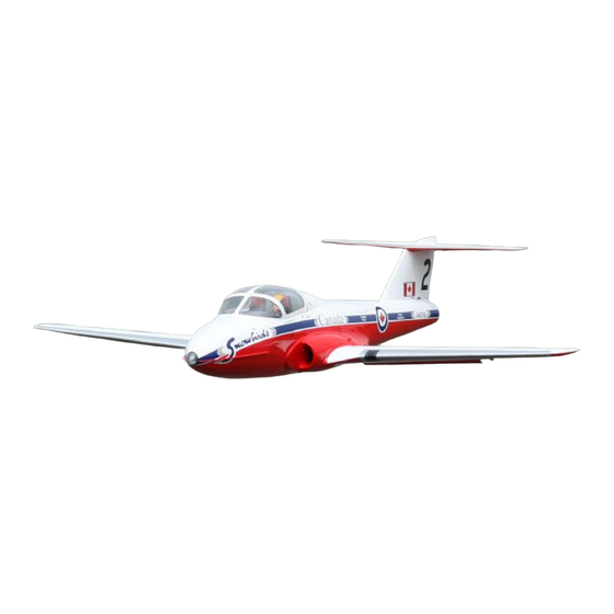
- Page 2 Canadian Forces primary jet trainer until 2000. The Tutor is perhaps best recognized as the aircraft used by the Snowbirds team, the scheme represented here. Other schemes are available, look at www.carf-models.com Following on from our hugely successful BAE Hawk, the Tutor is the perfect scale looking sports/ trainer jet.
-
Page 3: Table Of Contents
Contents Accessories . . . . . . . . . . . . . . . . . . . . . . . . . . . . . . . . . . . . . . . . . . . . . . . . . . . . . . . . . . 3 Wings . - Page 4 Composite ARF Tutor T-114 manual – techsupport@composite-arf.com...
-
Page 5: Accessories
Turbines in the 16kg (36lb) 160N thrust class are perfect for this aeroplane. All This list will help you chose the main additional CARF models display aeroplanes use JetCat items needed to finish your CARF-models turbines. CT-114. 5. Retractable Landing Gear sets are available Fuel Tank 200106. - Page 6 This works perfectly. both available separately from You could obviously use a gear door sequencer CARF-models.com. and save a channel there. Brakes use their own channel as does the throttle. The use of a PB...
-
Page 7: Wings
Wood/carbon laminated gear mounting plates glass paper to provide a good key. (Photo 3) are factory installed to accept the CARF-Models Tack glue the frame in place with CA and test recommended gear. The landing gear openings fit the servo to ensure correct positioning. - Page 8 Photo 2: Undercarriage legs. Composite ARF Tutor T-114 manual – techsupport@composite-arf.com...
- Page 9 Photo 3: Aileron servo mounts. control horns using an M3 x 16 Allen screw and radius servo arm to exploit the available travel. nylon stop nut. Fit the clevis in the outer hole of The Dubro high strength arms allow 22-25mm an 18-20mm radius arm.
- Page 10 Photo 4: Servo mounting. Photo 5: Flaps. Composite ARF Tutor T-114 manual – techsupport@composite-arf.com...
- Page 11 The flap linkage is assembled using two M3 x 140mm all-thread rods fitted with a locking nut and steel M3 clevis at each end. To allow perfect flap operation it is important to set the two flap servo arms neutral with your radio in the centre position of any control switch or lever (take off Flap), the arm should then be moved one spline forward of this position to aid...
-
Page 12: Gear Doors
Gear Doors The main gear doors are factory hinged ready for the operating system to be installed. CARF recommend using Robart 165 rams as supplied in the Air kit part No 250550. These are connected to the horn using ball links the ram requires a 2-56 stud which screws into the ram rod. - Page 13 Photo 6: Hinge tube. Photo 7: Wing root. Composite ARF Tutor T-114 manual – techsupport@composite-arf.com...
-
Page 14: The Main Landing Gear
Place the retract unit into the wing and retract the leg. Check clearance between the wheel and If you have purchased the CARF-Models Tutor gear door ram and mark the four mounting hole landing gear, installation is easy. The Behotec positions with a 4mm drill bit. - Page 15 Photo 8: Mounting lugs. Photo 9: A4 paper on the wing root. Composite ARF Tutor T-114 manual – techsupport@composite-arf.com...
- Page 16 Photo 10: Hinge. Photo 11: Leg door mechanism. Composite ARF Tutor T-114 manual – techsupport@composite-arf.com...
-
Page 17: Air System
The leg door is opened by a bent wire link shaped like an open rectangle. The closed end has a section of 3mm plastic tube bonded to the door approximately 98mm from the hinge. It’s important that the link pulls the door against a light tension with the leg fully retracted, this will stop the door opening in flight. -
Page 18: Horizontal Tail
Horizontal Tail using an M3 x 16 Allen screw and M3 stop nut. Adjust the clevis for a neutral elevator and lock The Tutor features a high or T tail position. The the nut against the clevis. The 2mm hinge wire fixing screws and brace tube spar have been is simply held in position with a spot of epoxy. - Page 19 Photo 13: Fixing the tail. Photo 14: Elevator servos. Composite ARF Tutor T-114 manual – techsupport@composite-arf.com...
- Page 20 Photo 15: Mounting holes marked and drilled. Photo 16: Exit holes for servo wires. Composite ARF Tutor T-114 manual – techsupport@composite-arf.com...
-
Page 21: Rudder
Photo 17: Hinge wire. Rudder . length is critical to provide perfect geometry with the factory fitted rudder horns. Screw the Very little work is needed to complete the rudder servo in position with the spline towards rudder, but it should be completed early as the the front using 2.9 x 13 screws. -
Page 22: Fuselage Assembly
Fuselage Assembly hinges on each door difficult. The doors operate reliably with three hinges on each door and The fuselage is a large item to handle during the forward section braced with a plywood rib construction, we recommend that you leave the bonded to the door. - Page 23 the supplied 16 x 3 plywood, 90mm long. (Photo 18) Screw the ram mount to the end of the support plate (note the screw under the ram body needs to be ground down or a CSK screw used for clearance) Add a ball link to the ram rod using a 2-56 stud provided.
- Page 24 Photo 19: Check the door operation. Photo 20: Nose access hatch. Composite ARF Tutor T-114 manual – techsupport@composite-arf.com...
-
Page 25: Nose Access Hatch
Nose Access Hatch Mark the hatch catch position on the rear lower corner of the hatch and cut a slot for the release The nose access hatch is factory cut, hinging is pin. Ensure the hatch pin goes flush with the via three offset hinges, as used on the nose gear hatch when fully open. -
Page 26: Nose Anti Stall Strips
Tip: when the four tab slots are cut push the Nose Anti Stall Strips blades in fully and using a marker pen held against the fuselage side draw a line on each The two flat strip, anti stall blades are installed on the nose centred on the moulded line that blade to follow while filing for a perfect fit. -
Page 27: Tail Pipe
Tail Pipe lines. Mark the chosen position and drill three holes. Note the lip width on the duct and drill The tail pipe supplied is very long requiring the holes half way across this. assembly inside the fuselage shell. (Photos 23 and 24) Clamp the duct to the bell-mouth and drill the centre hole only. - Page 28 Photo 23: Tail pipe. Photo 24: Tail pipe. Composite ARF Tutor T-114 manual – techsupport@composite-arf.com...
- Page 29 Photo 25: Tail pipe assembly. Photo 26: Turbine housing. Composite ARF Tutor T-114 manual – techsupport@composite-arf.com...
- Page 30 of any service requirements before removing the cover and cutting the openings. Ensure you remove all sharp edges from around the cut-outs. The front of the duct is left completely open and draws air from the whole fuselage. A FOD guard must be used! The standard set of leads supplied by JetCat is ample for the type of installation shown.
-
Page 31: Fuel Tank
Fuel Tank Use Tygon tubing as the clunk line and use the supplied felt clunk as supplied. At each joint The Fuel tank installation is very simple, the locking wire, or a second ring of Tygon tube cut factory fitted tank tray accepts the same tank as approx 3mm long slipped over the tube will seal the Hawk and is held in position with simple each joint. - Page 32 Photo 28: Cleaned tubes. Photo 29: Clunk line. Composite ARF Tutor T-114 manual – techsupport@composite-arf.com...
-
Page 33: Front Screen Windows
Front Screen Windows With the hinges complete, the glazing can be finished before moving onto the canopy locking Now is a good time to remove the front system. The canopy is large and requires a windows. The scribed lines are good to work secure fixing. -
Page 34: Installation Plate
All the equipment The main services installation plate is pre drilled supplied by CARF-models is fit for use and used and slotted to suit equipment recommended by by all the team pilots. The installation shown CARF-models. -
Page 35: Cockpit Tub
Photo 30: Installastion plate. Cockpit tub as a guide to the required angle. It leans back slightly. The cockpit floor sits on two wood rails The Tutor kit features an ABS moulded cockpit glued either side of the fuselage. The base and tub, this includes a dash board, floor, seats back bulkhead go in as one and are fitted with a and cockpit back. -
Page 36: Final Set Up
Final Set Up fat fuselage and thick wings drag. You will very quickly learn the various power settings The Tutor comes out very tail heavy, it has a required. Slow flight is a particular pleasure long tail moment and the pipe is in the ‘bullet with the large flaps producing plenty of drag. - Page 37 Assembled. Assembled. Composite ARF Tutor T-114 manual – techsupport@composite-arf.com...
- Page 38 Tail. Composite ARF Tutor T-114 manual – techsupport@composite-arf.com...
- Page 39 Nose wheel. Nose inspection hatch. Composite ARF Tutor T-114 manual – techsupport@composite-arf.com...
- Page 40 Cockpit. In flight. Composite ARF Tutor T-114 manual – techsupport@composite-arf.com...
- Page 41 Underside in flight. Composite ARF Tutor T-114 manual – techsupport@composite-arf.com...
- Page 42 Composite ARF Tutor T-114 manual – techsupport@composite-arf.com...
- Page 43 Composite ARF Tutor T-114 manual – techsupport@composite-arf.com...
Need help?
Do you have a question about the CL-41 Tutor and is the answer not in the manual?
Questions and answers