Table of Contents
Advertisement
Available languages
Available languages
Quick Links
ANLEITUNG FÜR EINBAU, BEDIENUNG UND WARTUNG
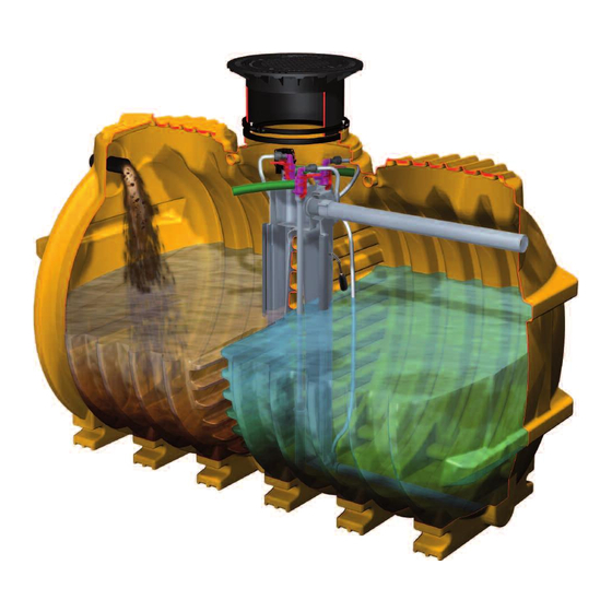
KESSEL-Kleinkläranlagen InnoClean PLUS
- die vollbiologische Kleinkläranlage
zur Reinigung häuslichen Abwassers
nach EN 12566, Teil III
InnoClean PLUS
Kleinkläranlage zum Einbau
ins Erdreich
in den Nenngrößen
EW 4 bis EW 50
Installation
der Anlage wurde durchgeführt von Ihrem Fachbetrieb:
Name/Unterschrift
Stand 2015/09
Inbetriebnahme
Datum
Bedienungsanleitung
D
Instructions de Montage
F
Installation Manual
GB
PL
Instrukcja Zabudowy
Istruzion per l'installazione
I
NL
Produktvorteile
Geringe Energiekosten
Geringe Wartungs- und Instand-
haltungskosten
Hohe Standzeit
durch Behälter aus Kunststoff
Dauerhafte Dichtheit durch
monolithisch rotierten Behälter
Keine Schwefelkorrosion
Leichter Einbau durch geringes Gewicht
Hohe Bruchsicherheit durch PE
Reinigungsklassen C, D, D+P
Zulassungen:
Z-55.31-625; Z-55.31-626; Z-55.31-627
Einweisung
Ort
Anleitung kann über
im Format DIN A 4
heruntergeladen werden!
Handleiding voor montage
Stempel Fachbetrieb
www.kessel.de
Seite 1
Page 47
Page 92
strona 137
pagina 182
pagina 227
Sach-Nr. 010-430
Advertisement
Chapters
Table of Contents

Related Manuals for Kessel InnoClean PLUS EW 4

Summary of Contents for Kessel InnoClean PLUS EW 4
- Page 1 ANLEITUNG FÜR EINBAU, BEDIENUNG UND WARTUNG KESSEL-Kleinkläranlagen InnoClean PLUS Anleitung kann über - die vollbiologische Kleinkläranlage www.kessel.de zur Reinigung häuslichen Abwassers im Format DIN A 4 heruntergeladen werden! nach EN 12566, Teil III Bedienungsanleitung Seite 1 InnoClean PLUS Instructions de Montage Page 47 Kleinkläranlage zum Einbau...
- Page 3 1. Sicherheitshinweise Achtung! Erstickungsgefahr beim Betreten der Anlage Das Personal für Montage, Bedienung, Wartung und Reparatur muss die entsprechende Qualifikati- on für diese Arbeiten aufweisen. Der Verantwortungsbereich, die Zuständigkeit und die Überwachung des Personals müssen durch den Betreiber genau geregelt sein. Die Betriebssicherheit der gelieferten Anlage ist nur bei bestimmungsgemäßer Verwendung gewähr- leistet.
-
Page 4: Table Of Contents
Inhaltsverzeichnis 1. Sicherheitshinweise ......................Seite 2. Allgemeines 2.1 Einsatzbereich ................ Seite 2.2 Anlagenbeschreibung .............. Seite 2.3 Anlagenkonfiguration .............. Seite 2.4 Maße und Nutzvolumen ............Seite 2.5 Funktionsbeschreibung ............Seite 13 3. Verpackung, Transport 3.1 Verpackung ................Seite 15 und Lagerung 3.2 Transport................. - Page 5 Sehr geehrter Kunde, wir freuen uns, dass Sie sich für ein Produkt von KESSEL entschieden haben. Die gesamte Anlage wurde vor Verlassen des Werkes einer strengen Qualitätskontrolle unterzogen. Prüfen Sie bitte den- noch sofort, ob die Anlage vollständig und unbeschädigt bei Ihnen angeliefert wurde. Im Falle eines Transportschadens beachten Sie bitte die Anweisungen in Kapitel „Gewährleistung“...
-
Page 6: Einsatzbereich
2. Allgemeines 2.1 Einsatzbereich zung wird von einem Kompressor bereitgestellt und durch InnoClean PLUS , die Kleinkläranlage von KESSEL, ist eine eine Steuereinheit vollautomatisch geregelt. Der Kompres- Reinigungsanlage für häusliche Abwässer nach EN 12566, sor und die Steuerung sind zum freien Einbau in frostge- Teil III. -
Page 7: Anlagenkonfiguration
2. Allgemeines 2.3 Anlagenkonfiguration Seitenansicht Behälter EW 4 - 6 Nutzvolumen 4800 l Seitenansicht Behälter EW 8 -10 Nutzvolumen 7600 l Frontansicht... -
Page 8: Maße Und Nutzvolumen
2. Allgemeines 2.4 Maße und Nutzvolumen... - Page 9 2. Allgemeines Anlagenkonfiguration EW 4, EW 6, EW 8 und EW 10 Probenahmebehälter Klarwasserheber Beschickungsheber Notüberlauf Überschussschlammheber Rmax Rmin Schwimmerschalter Rohrbelüfterelement Zulauf Ablauf Grobfang und Belebung Schlammspeicher Rmax Rmax Rmin Rmin...
- Page 10 2. Allgemeines Anlagenkonfiguration EW 12, EW 14, EW 16 und EW 20 Probenahmebehälter Klarwasserheber Beschickungsheber Notüberlauf Überschussschlammheber Rmax Rmin Schwimmerschalter Rohrbelüfterelement Behälter 1 Zulauf Ablauf Behälter 2 Rohrbelüfterelement Belebung Grobfang und Schlammspeicher Rmax Rmin Rmin Rmax...
- Page 11 2. Allgemeines Anlagenkonfiguration EW 22 bis EW 30 Klarwasserheber Probenahmebehälter Notüberlauf Beschickungsheber Überschussschlammheber Schwimmerschalter Rohrbelüfterelement Rohrbelüfterelement 2 Belebung Grobfang und Schlammspeicher Belebung Grobfang und Schlammspeicher Ablauf Zulauf Behälter 1 Behälter 2 Behälter 3 Frontansicht Rmax Rmin Rmax Rmin Rmax Rmin...
- Page 12 2. Allgemeines Anlagenkonfiguration EW 32 bis EW 50 Klarwasserheber Probenahmebehälter Notüberlauf Beschickungsheber Überschussschlammheber Schwimmerschalter Rohrbelüfterelement Rohrbelüfterelement 2 Frontansicht Rmax Behälter 3 Behälter 4 Rmin Ablauf Behälter 1 Behälter 2 Belebung Grobfang und Belebung Schlammspeicher Zulauf Behälter 5 Behälter 6 Ablauf Grobfang und Grobfang und Schlammspeicher...
-
Page 13: Funktionsbeschreibung
2. Allgemeines 2.5 Funktionsbeschreibung Der Klärprozess wird vollautomatisch von der Steuereinheit geregelt. Ein Klär- zyklus dauert ca. 8 Stunden und wird durch Abführen des geklärten Wassers beendet. Der Klärungsprozess basiert auf Mikroor- ganismen, die während der Behandlungs- phase das Abwasser reinigen. 1. - Page 14 2. Allgemeines 4. Absetzphase Nach der Behandlungsphase folgt eine zweistündige Absetzphase. Alle in dem Ab- wasser enthaltenen Feststoffe, sowie der Belebtschlamm setzen sich am Beckenbo- den ab somit bildet sich im oberen Bereich eine Klarwasserschicht und am Boden eine Schlammschicht aus Mikroorganismen. 5.
-
Page 15: Verpackung
3. Verpackung, Transport und Lagerung Das Kapitel Sicherheitshinweise ist zu beachten! • Die Behälter sind gegen unzulässige Lageveränderungen während der Beförderung zu sichern. Durch die Art der 3.1 Verpackung Befestigung dürfen die Behälter nicht beschädigt werden. Eine Verpackung der Behälter zum Zwecke des Transports bzw. -
Page 16: Einbauort
4. Einbau und Montage Während der Zwischenlagerung der Kleinkläranlage 4.2 Baugrube sowie bis zum Abschluss der Einbauarbeiten, müssen an der Baustelle geeignete Sicherungsmaßnahmen getrof- fen werden, um Unfälle und Beschädigungen der Klein- kläranlage zu verhindern. Das Kapitel Sicherheitshinweise ist zu beachten. ... -
Page 17: Einsetzen
4. Einbau und Montage ≥20cm ≥30cm ’ ≥30cm ≥30cm ≥50cm ≥50cm ≥30cm ≥30cm ≥30cm ≥30cm b nach DIN 4124 3-10cm ≥70cm ≥70cm Unterbau: Schotter 0/16 verdichtet mit Dpr ≥ 97% Tragschicht (TS): Bei Gruppe E4 (SLW 60) Lastverteilplatte Behälterbett: Sand verdichtet mit Dpr ≥ 97% gemäß... - Page 18 Bohrkrone und Rohrdurchführungsdich- über ein stetiges Gefälle von ≥ 2° zum Behälter verfügen. Für tung von KESSEL zu verwenden . KESSEL empfiehlt die Ver- die Durchführung durch die Gebäudewand empfiehlt KESSEL wendung eines Aktivkohlefilters zur Vermeidung von Geruchs- auf handelsübliche Wanddurchführungen zurück zu greifen...
-
Page 19: Verlegung Der Verbindungsleitungen
4.9 Montage der Aufsatzstücke Zuerst die Dichtung (siehe Zeichnung 4.9) in die Öffnung im Dom einlegen. Das teleskopische KESSEL-Aufsatzstück im unteren Bereich mit Gleitmittel einfetten und in die Behälteröffnung einstecken, in die gewünschte Position bringen. Alternativ kann Gleitmit- tel auch auf den Dichtring aufgetragen werden. -
Page 20: Befüllen
4. Einbau und Montage Auslauf Zulauf 4.10 Abschliessende Befüllung des Behälters Wasserfüllstandshöhe (in cm) vor Inbetriebnahme Vor dem Verfüllen nochmaliges Kontrollieren der Zu- und Schlammfang Belebungskammer Ablaufleitung, sowie der Entlüftungsleitung und des Ka- belleerrohrs. Das Aufsatzstück mit der Geländeoberkante abgleichen. -
Page 21: Einbau Steuereinheit Und Kompressor
Umgebungsluft muss frei von entflammbaren oder aggres- Allgemeine Hinweise siven Gasen oder Dämpfen sein. ACHTUNG: KESSEL empfiehlt, für die Ausführung von Die Schlauchleitung ist so kurz und so gerade wie möglich elektrischen Anschlüssen, einen Fachbetrieb des Elek- zwischen Steuerung und Behälter zu verlegen. Richtungs- trohandwerks zu beauftragen. - Page 22 4. Einbau und Montage Montage und Anschluss innherhalb frostgeschützter Räume Die Wandkonsole (optionales Zubehör) oder eine alternative Abstellmöglichkeit ist waagerecht an der Wand zu fixieren. Das Steuergerät durch Lösen der vier stirnseitigen Kreuzschlitzschrauben öffnen und dessen Rückwand mit den mitgelieferten vier Kreuzschlitzschrauben an den vorgebohrten Stellen der Wandkonsole (unter- halb der Abstellfläche für den Kompressor) befesti- gen.
- Page 23 4. Einbau und Montage Anschluss der Kompressoren JDK 150, 200 und 250 1. Zuschneiden 2. Anschließen £ max. 40 mm 35mm 45mm Bild 1 Bild 2 Optionale Anschlüsse am Schaltgerät: Achtung: Alle optionalen Anschlüsse sind nur durch Elektrofachkräfte durchzuführen. SICHERUNG Fuse Fusible 230VAC 50Hz...
-
Page 24: Anlage In Betriebsbereitschaft Setzen
Das Kapitel Sicherheitshinweise ist zu beachten! (S.2) Die Inbetriebnahme wird von einem Fachbetrieb oder einem Syst em st ar t Sy s t em di agnos e KESSEL-Beauftragten durchgeführt (gegen Aufpreis). Folgende Personen sollten bei der Übergabe anwesend sein: - Abnahmeberechtigter des Bauherrn - Fachbetrieb 0. -
Page 25: Pflichten Des Betreibers
5. Inbetriebnahme ausgerüstet sein. einen schnelleren Aufbau der Biologie zu gewährleisten. Bei der Erstinitialisierung der Anlage fragt das Steuer- Darüber hinaus kann es sinnvoll sein, nach jeder Primär- gerät nach vier Grundeinstellungen. Im Display des schlammentsorgung (siehe Punkt 6.4 Entsorgung) die Steuergerätes erscheint die Frage nach: Einstellung T20 ("Rückführung Urlaubsphase") zu redu- 1. -
Page 26: Eigenkontrolle Des Betreibers
6. Betrieb und Entsorgung Wenn Sie sich an nachfolgende Empfehlungen halten, kön- Die Wasserbehörde kann Einsicht in dieses Betriebstage- nen Sie unnötige Reparaturkosten vermeiden und die Le- buch verlangen. Im Einzelnen sind Sie dazu aufgefordert, bensdauer Ihrer Anlage erhöhen: folgende Kontrollen regelmäßig durchzuführen: •... -
Page 27: Was Nicht In Die Biol. Kleinkläranlage Gehört
6. Betrieb und Entsorgung 6.3 Was nicht in eine biologische Kleinkläranlage gehört Folgende Hinweise sollten Sie im eigenen Interesse beachten: Feste oder flüssige Stoffe, Was sie anrichten Wo sie gut aufgehoben sind die nicht in den Ausguss oder in die Toilette gehören Asche zersetzt sich nicht Mülltonne... -
Page 28: Entsorgung
80 cm, ist der Inhalt des Schlammfanges durch Wichtiger Hinweis: einen Entsorgungsfachbetrieb zu entsorgen (Messung siehe KESSEL empfiehlt, bei der Entsorgung des Schlammfangs 6.2 Eigenkontrolle des Betreibers oder durch Wartungs- bzw. der Vorklärkammer (insbesondere bei eher unterlastig firma). -
Page 29: Vorklärung Und Belebung
7. Wartung 7.1 Wartung Vorklärung + Belebung den grauen Luftschlauch heraus. Anschließend öffnen Sie den roten Verschlusshebel und ziehen den Luftheber aus Hinweis: Informieren Sie sich, wer in Ihrem Gebiet für die dem Klärturm heraus. Somit kann der Heber inkl. innenlie- Wartung von Kleinkläranlagen zuständig ist. -
Page 30: Kompressor
Zusätzlich sind die Ventilboxen auf Verschmutzung zu prü- Kompressors führen. fen und ggf. zu tauschen. Eine Ersatzteilliste erhalten Sie über den Kundendienst der KESSEL AG. Achtung! Benutzen Sie keine Lösungsmittel zur Filter- reinigung, da dies zu Schaden führen kann. Generell ist zu prüfen: - Strömt Luft aus dem Luftaustritt? - Page 31 7. Wartung Einstellparameter für Steuerung 331-105 InnoClean PLUS...
- Page 32 8. Steuerung der Kleinkläranlage 8. Bedienung des Schaltgerätes Display/Anzeigenfeld Bewegungstasten/Richtungstasten Bestätigungstaste/OK-Taste Zurücktaste/ESC-Taste Kontrolllampe für Betriebsbereitschaft Kontrolllampe für Störungsmeldung Netzabschlusskabel Netzanschlus für Kompressor Anschluss Druckluftsensor Anschlussmöglichkeiten für externen Signalgeber Anschluss für Ventilblock Anschlussbuchse für potentialfreien Kontakt Menüführung Alarmtaste kann der akustische Alarm quittiert werden. Die Menüführung des Schaltgerätes ist in die Systeminfo, Der Stand-by-Modus wird für mind.
-
Page 33: Systemmenü
8. Steuerung der Kleinkläranlage 8.1.System-Menü Anzeige der Hierarchie-Ebene Uhrzeit Anzeige der aktivierten Schwimmer, sowie deren Position Anzeige der Phase Anzeige der aktuell abgelaufenen Zeit der jeweil. Phase Anzeige von Alarm/Fehlerinformationen 8.2.1 Betriebsstunden 8.2 Informationsmenü Anzeige aller Laufzeiten der Anlage. 8.2.2 Ereignisse / Fehler Systeminfo Informationen Betriebsstunden... -
Page 34: Einstellungsmenü
8. Steuerung der Kleinkläranlage 8.3.3 Wartungstermin Eingabe des nächsten Wartungstermins durch den Wartungspartner. 8.4.1 Parameter 8.4 Einstellungsmenü Änderung werkseitig hinterlegter Parameter. Hinweis: Jede Änderung wird mit Bestätigung der Parameter OK-Taste sofort übernommen. Zusätzlich gibt es Systeminfo Informationen Parameterspeicher beim Verlassen des Menüs die Möglichkeit, diese Werte in dem Parameterspeicher (siehe Punkt Datum / Uhrzeit Wartung... -
Page 35: Seite
9. Störungen und Abhilfemaßnahmen Behebung Fehler Mögliche Ursache Fehleranzeige Schaltgerät - Einstellung auf 150 cm - Niveau zu niedrig eingestellt Hochwasser Schwimmer 2+ - Überprüfung der Zulaufmengen - Zulaufmenge zu hoch Hochwasser Sensor der Anlage Wasserstand in der Belebungs- - Überprüfung der hydraulischen kammer hat max. - Page 36 9. Störungen und Abhilfemaßnahmen Fehler Mögliche Ursache Behebung Akkuspannung zu hoch - Akku einsetzen - Akku nicht vorhanden - Kontaktfehler am Akku - Akku auf Polarität und Sitz prüfen - Schaltgerät tauschen Relaisfehler - Relaiskontakt im Schaltgerät “verklebt” - Vorsicherung und/oder - Die Anlage ist stromlos Auf dem Display der Steuerung FI-Schalter überprüfen...
- Page 37 9. Störungen und Abhilfemaßnahmen Fehler Mögliche Ursache Behebung wiederherstellen. nicht mehr angeschlossen. - Ist beim Handbetrieb Klarwasser- - Magnetventil defekt. abzug kein deutliches Öffnungs- geräusch feststellbar, Service an- rufen. - Die Einleitungsstelle muss wieder - Es kommt zum Rückstau an der freigängig gemacht werden.
-
Page 38: Seite
10. Gewährleistung 1. Ist eine Lieferung oder Leistung mangelhaft, so hat KESSEL abscheider, Schächte, Kleinkläranlagen und Regenwasserzi- nach Ihrer Wahl den Mangel durch Nachbesserung zu beseiti- sternen auf 20 Jahre bezüglich Behälter. Dies bezieht sich auf gen oder eine mangelfreie Sache zu liefern. Schlägt die Nach- die Dichtheit, Gebrauchstauglichkeit und statische Sicherheit. - Page 39 Anlagenpaß / Werksabnahme...
- Page 40 12. CE Konformitätserklärung / Leistungserklärung...
- Page 41 Std. Std. Std. nein nein nein nein Std. Std. Std. nein nein nein nein Std. Std. Std. nein nein nein _______________________________________________ _______________________________________________ (Ort, Datum) (Unterschrift des Betreibers) Macintosh HD:Users:kessel katalog:Public:Kessel Katalog:QUARK:EBAS Quark:010 430 Inno Clean 2 Generation:Betriebstagebuch InnoClean doc...
- Page 42 Wartungsprotokoll KESSEL InnoClean PLUS gem. DIN 4261 -100 Name des Betreibers: Standort: Typ der Anlage: Seriennummer: Reinigungsklasse: Dichtheitsprüfung am: Einwohnergleichwert: Inbetriebnahme am: Kontrolle Mängel Ausführung Anlagenteil / Funktion Bemerkung Kontrolle nein Mängel nein Ausführung Anlagenteil / Funktion Bemerkung Erster Eindruck...
- Page 43 Laufzeit (h) Bewertung / Auswirkung geändert auf Betriebsstunden Laufzeit Klarwasserheber Laufzeit Beschickungsheber Laufzeit Belüftung Gesamtlaufzeit Füllstände Schlammabfuhr Füllstandstiefe Schlammfang Letzte Schlammabfuhr am: Füllstandshöhe Primärschlamm Füllstandstiefe Belebtkammer nein Schlammabfuhr veranlassen: Belebtschlammvolumen ja, bis: Abwasseranalyse (Parameter soweit messbar) CSB (mg/l) -N Nitrat (mg/l) Geruch (mg/l) -N Nitrit (mg/l)
- Page 44 15. Technische Daten...
- Page 45 16. Ersatzteile Pos. Bezeichnung Art.Nr. Pos. Bezeichnung Art.Nr. Schlauchverbinder auf Anfrage Länge 820 mm auf Anfrage Luftanschlussbogen auf Anfrage Länge 1170 mm auf Anfrage HTK-Bogen 63050 Länge 1370 mm auf Anfrage Aushebeschlüssel 915595 Dualverschlusshebel 680139 Lippendichtung 860116 Spiralschlauch Ø 50 mm (Meterware) 680073 Belüfterkerze für InnoClean mit Klärturm Klemmring Aufsatzstück...
- Page 46 16. Ersatzteile Pos. Bezeichnung Art.Nr. Pos. Bezeichnung Art.Nr. Membrankompressor gesamt Ersatzmembrane (1 Paar) 680465 JDK-S-100 680469 JDK 60-120 680466 JDK-S-120 680470 JDK 150-500 680178 JDK-S-150 680471 Stützhülse 97742 JDK-S-200 680472 PP Bogen 90° 3/4’’ x 20 (nur bei 18 b, c, d) auf Anfrage JDK-S-250 680473...
- Page 47 NOTICE D´INSTALLATION, DE MONTAGE ET D´ENTRETIEN Micro station d'épuration KESSEL InnoClean PLUS Micro station d'épuration totalement biologique pour le traitement des eaux usées ménagères, selon la EN 12566, partie III Micro station d´épuration InnoClean PLUS pour une L´ínstruction de service peut être Installation à...
- Page 48 1. Consignes de sécurité Attention ! Risque d'asphyxie en cas d´intervention dans la cuve. Le personnel affecté au montage, à la manipulation, à la maintenance et aux réparations doit présenter la qualification correspondant à ces travaux. L'exploitant doit dicter les règles exactes concernant les domaines de responsabilité, les compétences et la surveillance du personnel.
- Page 49 Sommaire 1. Consignes de sécurité ......................Page 48 2.1 Champ d'application .............. Page 51 2. Généralités 2.2 Description du système ............Page 51 2.3 Configuration de l´installation..........Page 52 2.4 Dimension et volume .............. Page 53 2.5 Description du fonctionnement ..........Page 58 3.1 Emballage................
- Page 50 Cher client, Nous nous réjouissons que vous vous soyez décidé en faveur d'un produit de KESSEL. L'ensemble du système a été soumis à un contrôle de qualité sévère avant de quitter l'usine. Veuillez contrôler immé- diatement si le système a bien été livré chez vous complet et sans dommages. Veuillez tenir compte, en cas de dommages pendant le transport, des instructions du chapitre «...
-
Page 51: Généralités
2.1 Champ d'application jour. Ce système n'est à pas prévu pour les eaux pluviales, InnoClean PLUS, la micro-station de KESSEL est un systè- les eaux usées provenant de l'élevage d'animaux, les eaux me de traitement des eaux usées domestiques, conforme à... -
Page 52: Configuration De L´installation
2. Généralités 2.3 Configuration des installations Vue de face, Cuve EQ 4 - 6 volume utile 4800 l Vue de face, conteneur EQ 8-10 volume utile 7600 l Vue de face... -
Page 53: Dimension Et Volume
2. Généralités 2.4. Masse et volume utile... - Page 54 2. Généralités Configuration des installations EQ 4, EQ 6, EQ 8 EQ et 10 Bac de prélèvement Probenahmebehälter Klarwasserheber Elément de renvoie des eaux claires Beschickungsheber Notüberlauf Capteur de chargement Trop plein Elément de renvoie d'excédent de boue Überschussschlammheber Rmax Rmin Schwimmerschalter Commutateur de flotteur...
- Page 55 2. Généralités Configuration des installations EQ 12, EQ 14, EQ 16 et EQ 20 Elément de renvoie d'excédent de boue Capteur de chargement Elément de renvoie des eaux claires Trop plein Cartouche de ventilation aérateur 1 Commutateur de flotteur Cartouche de ventilation aérateur 2 Grobfang und Dépôt de matière Belebung...
- Page 56 2. Généralités Configuration des installations EQ 22 - EQ 30 Elément de renvoie des eaux claires Klarwasserheber Probenahmebehälter Bac de prélèvement Notüberlauf Trop plein Beschickungsheber Capteur de chargement Überschussschlammheber Elément de renvoie d'excédent de boue Schwimmerschalter Commutateur de flotteur Rohrbelüfterelement Rohrbelüfterelement 2 Cartouche de ventilation aérateur 2 Cartouche de ventilation aérateur1...
- Page 57 2. Généralités Configuration des installations EQ 32 - EQ 50 Elément de renvoie des eaux claires Klarwasserheber Bac de prélèvement Probenahmebehälter Notüberlauf Trop plein Beschickungsheber Capteur de chargement Überschussschlammheber Elément de renvoie d'excédent de boue Schwimmerschalter Commutateur de flotteur Rohrbelüfterelement Rohrbelüfterelement 2 Cartouche de ventilation aérateur1 Cartouche de...
-
Page 58: Description Du Fonctionnement
2. Généralités 2.5. Description du fonctionnement Le processus d'épuration est automatique- ment régulé par le gestionnaire. Un cycle d'épuration dure environ 8 heures et se ter- mine par l’évacuation de l'eau purifiée. Le processus de clarification se base sur des micro-organismes qui se charge de la pu- rification des eaux. - Page 59 2. Généralités 4. Phase de décantation Une phase de décantation de 2 heures suit la phase de traitement. Toutes Les matiè- res solides contenues dans les eaux usées ainsi que la boue activée se déposent au fond du bassin, ce qui est l’origine de for- mation d´une couche d'eau claire dans la zone supérieure, tandis qu’une couche de boue des micro-organismes se dépose au...
-
Page 60: Emballage, Transport
3. Emballage, transport et stockage l Les réservoirs doivent être sécurisés contre tout change- Il faut tenir compte du chapitre traitant des consignes de sécurité ! ment de position non autorisé pendant leur convoyage. Les réservoirs ne doivent pas être endommagés par le type de 3.1 Emballage fixation. -
Page 61: Installation Et Montage
4. Installation et montage Pendant l'entreposage d'une micro station d'épuration stallés dans une armoire de commande optionnelle. ainsi que jusqu'à la conclusion des travaux d'installati- En cas d’installations avec plusieurs cuves, la distance ma- on, des mesures de protection appropriées doivent être ximale est 3,0 m. -
Page 62: La Pose
4. Installation et montage ≥20cm ’ ≥30cm ≥30cm ≥30cm ≥50cm ≥50cm ≥30cm ≥30cm ≥30cm ≥30cm b nach DIN 4124 3-10cm ≥70cm ≥70cm Couche de base : gravier 0/16 d'un degré de compactage <Dpr> à 97 % Couche de recouvrement : si classe E (poids lourd SLW 60) plaque de répartition de la charge suivant le calcul de la Lit de la cuve : sable d'un degré... - Page 63 Dans ce cas, il faut utiliser la scie cloche corres- pente permanente de ≥ 2 ° ° vers la cuve. Pour la réalisation pondante et le joint adéquat KESSEL (voir la figure en page du mur du bâtiment, KESSEL recommande d'avoir recours 5).
-
Page 64: Montage Des Tuyaux Pneumatiques
4. Installation et montage Observations pour les Innocleans EW 12 jusqu`à EW30 Les conduites de commande sont à placer en gaine et à Pour la ventilation de la boue active, il faudra monter direc- raccorder au gestionnaire et au bloc de vannes pneuma- tement la cartouche de ventilation dans le compartiment à... -
Page 65: Mise En Place Des Rehausses
Avec un lubrifiant, graisser la partie bisoute de la rehausse de ventilation et la gaine pour câbles. Egaliser la rehausse KESSEL et le joint et emboiter dans le trous d´homme par rapport au terrain jusqu’à la position souhaité, puis fixer au moyen d’un collier Ajuster les niveaux de fluide dans les deux chambres pour de serrage (accessoire optionels). -
Page 66: Installation Du Gestionnaire Et Du Compresseur
L'air ambiant aspiré ne doit Instructions générales pas contenir des vapeurs ou de gaz inflammables ou agres- ATTENTION : KESSEL recommande de faire exécuter sifs. les raccordements électriques par une entreprise spé- La tuyauterie flexible doit être aussi courte et rectiligne que... - Page 67 4. Installation et montage Montage et raccordement à l'intérieur des chambres abri du gel La console murale doit être fixée à l’horizontale sur le mur, au moyen des deux vis et chevilles fournies à la livraison. Ouvrir le boîtier de commande en desserrant les qua- tre vis à...
- Page 68 4. Installation et montage Branchement des compresseurs JDK 150, 200 et 250 1. Couper 2. Brancher £ max. 40 mm 35mm 45mm fig. 1 fig. 2 Raccords optionnels sur l'appareil de commande : Attention: tous les raccords optionnels doivent être exécutés par des électriciens de métier. SICHERUNG Fuse Fusible...
-
Page 69: Mise En Service De L´installation
Syst em st ar t Sy s t em di agnos e systéme diagnose prise spécialisée ou un mandataire KESSEL (contre majorati- on). Les personnes suivantes doivent être présentes lors du transfert : - le représentant du maître de l'ouvrage 0. -
Page 70: Recommandation À L´utilisateur
5. Mise en service Instruction : la conduite de réseau doit être équipée d’un auto- formation plus rapide de la biologie. En outre, il peut être ra- mate de protection FI. tionnel, après chaque élimination des boues primaires, de Lors d'une première initialisation de l'installation, le boîtier de réduire le réglage T20 (voir point 6.4 Elimination des déchets) commande demande quatre mises au point de base. -
Page 71: Vérification Par L´utilisateur
6. Entretien et vidange de boue Cette adaptation aux différentes quantités d'eaux usées est Le contrôle doit être effectué conformément aux intervalles réglée automatiquement par la commande. La phase corre- indiqués dans le journal de service (chapitre 13). Les écarts spondante est affichée sur le gestionnaire. -
Page 72: Consignes D´enlèvement Des Boues
6. Entretien et vidange de boue Contrôles semestriels du conteneur, cela signifie qu’on a atteint environ 30% de la Maintenance par une entreprise spécialisée. Il faut tenir capacité d'absorption. compte des indications des services publics compétents. Si la hauteur de boue est de environ 80 cm par rapport au fond 6.3 Points ne faisant pas partie d’une micro station d'épuration biologique Dans votre propre intérêt, vous devez faire attention aux instructions suivantes: Matière lourde ou fluide, qui... -
Page 73: Elimination
être retiré par une entreprise spécialisée dans Importante remarque: le traitement des déchets (Mesure, voir 6.2 propres con- KESSEL recommande, lors de l'élimination des déchets trôles de l'exploitant ou par la société de maintenance). provenant du séparateur de boue ou de la chambre de pré- épuration (en particulier, dans le cas d'installations peu... -
Page 74: Maintenance
7. Maintenance 7.1 Maintenance décantation primaire + lit bactérien peut être nécessaire de retirer et de nettoyer le système air-lift. Pour cela, déverrouillez la fermeture rapide du vérin Remarque : Informez-vous pour savoir qui est compétent et retirez le tuyau gris. Ensuite, ouvrez le levier de ferme- dans votre région pour la maintenance de micro station ture rouge et retirez l´air-lift de la tour d'épuration. -
Page 75: Compresseur
échéant, de les remplacer. Vous recevez une liste de pièces de rechange auprès du service après-vente de KESSEL AG: ATTENTION ! N'utilisez aucun solvant pour le nettoyage de filtre car cela peut l’endommager. - Page 76 7. Maintenance Paramètres de réglage pour la commande InnoClean PLUS...
-
Page 77: Programmation De La Micro Station
8. Programmation de la micro station Ecran / champ d'annonces Touches de mouvement / touches de direction Touche de validation / Touche OK Touche retour / clé de sortie Voyant de contrôle pour ordre de marche Voyant de contrôle pour message de panne Câble d´alimentation secteur Câble d´alimentation pour le compresseur Raccord du capteur pneumatique... -
Page 78: Menu Du Système
8. Programmation de la micro station 8.1.Menu de système Système Information Information Informationen Systeminfo Heure: 00:00:00 Uhrzeit: 00:00:00 Flotteur1: Marché/arrêt Schwimmer 1: Ein / Aus TX: Phase T1 - T24 TX: (Phase T1 bis T24) Maintenance TX1: (temp: 00:00:00) Wartung TX1: (Zeit: 00:00:00) Réglages Einstellungen... -
Page 79: Menu - Programmation
8. Programmation de la micro station 8.3.3 Date de maintenance Entrée par le responsable de la maintenance de la prochaine date de maintenance. 8.4.1 1 Paramètres 8.4 Menu de programation Modification des paramètres réglés en usine. Remarque : chaque modification est immédiatement Paramètre Parameter prise en compte en confirmant avec la touche OK. -
Page 80: Pannes - Solutions
9. Pannes - solutions Défaut Cause possible Elimination des défauts Indicateur de défauts sur l'ap- - Niveau réglé trop bas - Réglage sur 150 cm pareil de commande - Flux d’arrivée trop élevé - Contrôle des influents Flotteur niveau max.2 + capteur - Air lift pour l´eau purifier défectu- de l'installation de niveau max. - Page 81 9. Pannes - solutions Défaut Elimination des défauts Raisons - Mettre en place une batterie - Manque batterie Tension de batterie trop haute - Contrôler la polarité et la position - Défaut de contact aux batteries de la batterie - Remplacer le gestionnaire - Le relais dans le gestionnaire Défaut de relais est collé...
- Page 82 9. Pannes - solutions Elimination des défauts Cause possible Défaut - Si, en service manuel pour le renvoi - Electrovanne défectueuse. d'eau purifiée, aucun bruit de déclanchement de vanne n'est - Formation d’un bouchon au ni- perceptible, appeler le service veau de l'ouverture.
-
Page 83: Garantie
écrit sera envoyé dès que ces manques auront été constatés. 2. KESSEL rappelle que l'usure n'est pas un défaut pris en compte KESSEL est responsable des réparations et livraisons postérieu- par la garantie. Il en est de même pour les défauts dus à une res dans les mêmes conditions que celles de l'objet du contrat... -
Page 84: Certificat De L´installation/ Mise En Service
11. Certificat de l´installation/ mise en service... -
Page 85: Certificat De Conformité
12. Certificat de conformité /declaration de performance... -
Page 86: Rapport Journalier
) fonctionnement Ventilation Alimentation Evacuation des EU traitées réparties zone de traitement ( ) _______________________________________________ _______________________________________________ (A ..., Date) (Signature) Date Contrôle journalier Contrôle hebdomadaire Contrôle mensuel Macintosh HD:Users:kessel-katalog:Public:Kessel-Katalog:QUARK:EBAS_Quark:010-430_Inno-Clean_2. Generation:Betriebstagebuch_Wartungscheckliste:InnoClean_neu_ Übersetzungen:Betriebstagebuch InnoClean Ver.FR.doc... -
Page 87: Instructions D´entretien
14. Instructions d´entretien... -
Page 88: Piéces Détanchée
Tuyau connecteur sur demande longueur 1170 mm sur demande Coude d'aération sur demande longueur 1370 mm sur demande Coude Kessel HTK 63050 touches de levage 915595 Levier de vérouillage 680139 oint à lèvre 860116 Bougie d´aération 50 mm 680073 La bague de serrage attachement pièce... - Page 89 15. Piéces détachée InnoClean PLUS Pos. Désignation Pos. Désignation Compresseur global Membrane de remplacement (1 paire) 680465 JDK-S-100 680469 JDK 60-120 680466 JDK-S-120 680470 JDK 150-500 680178 JDK-S-150 680471 manchon de support 97742 JDK-S-200 680472 PP coude de 90 ° 3/4 '' x 20 (seulement 18 b, c, d) sur demande Tuyau d'air 19 x 25 mm 97738...
-
Page 90: Information Technique
16. Information technique... - Page 91 Leader en solution d’assainissement Construction de logements privés sans raccordement au réseau d’assainissement public 1 2 3 4 1 2 3 4 Construction de logements Construction publique, par privés sans raccordement au exemple aménagement de loisirs réseau d’assainissement public 1 2 3 4 Construction industrielle 2 3 5...
- Page 92 INSTALLATION, OPERATING AND MAINTENANCE INSTRUTIONS KESSEL-Septic-System InnoClean PLUS - the fully biological septic system for domestic sewage purification according to EN 12566, part III InnoClean PLUS - Septic-System for installation User´s Manual in DIN A 4 size can be in the ground in nominal...
-
Page 93: Safety Instructions
1. Safety instructions Caution! Danger of suffocation when entering the plant. The personnel for assembly, operation, maintenance and repair must possess the appropriate quali- fication for this type of work. The area of responsibility, the authority and the supervision of personnel must be exactly regulated by the operator. - Page 94 Table of contents 1. Safety instructions ......................Page 93 2. General 2.1 Area of application ..............Page 96 2.2 Description of system .............. Page 96 2.3 Plant configuration ..............Page 97 2.4 Dimensions and useful volume ..........Page 98 2.5 Functional description ............
- Page 95 Dear customer, we are pleased that you have decided to buy a KESSEL product. The entire plant has been subjected to a stringent quality control before it has left our factory. Please nevertheless check immediately whether the plant has been delivered to you complete and undamaged. In case of any transport damage, please refer to the instructions in the chapter "Warranty"...
-
Page 96: General
2. General 2.1 Area of application InnoClean PLUS, the septic system from KESSEL, is a clea- dry rooms which are safeguarded from flooding. In addition ning unit for domestic wastewater in keeping with DIN 4261 to the septic system, provision must be made for a suitable Part II / EN 12566. -
Page 97: Plant Configuration
2. General 2.3 Plant configuration Side view, tank EW 4 – 6 useful volume 4800 l Side view tank EW 8 -10 useful volume 7600 l Front view... -
Page 98: Dimensions And Useful Volume
2. General 2.4 Dimensions and useful volume... - Page 99 2. General Plant configuration EW 4, EW 6, EW 8 and EW 10 Sampling vessel Probenahmebehälter Klarwasserheber Clear water syphon Beschickungsheber Notüberlauf Feed sensor Emergency overflow Überschussschlammheber Excess sludge syphon Rmax Rmin Schwimmerschalter Floating switch Rohrbelüfterelement Pipe aerator element Inlet kg/d BSB5 Freight/day /d Sewage inlet/day /h Sewage inlet//hour...
- Page 100 2. General Plant configuration EW 12, EW 14, EW 16 and EW 20 Sampling vessel Probenahmebehälter Klarwasserheber Clear water syphon Feed sensor Beschickungsheber Notüberlauf Emergency overflow Überschussschlammheber Excess sludge syphon Rmax Rmin Schwimmerschalter Floating switch Rohrbelüfterelement Pipe aerator element Inlet kg/d BSB5 Freight/day /d Sewage inlet/day /h Sewage inlet//hour...
- Page 101 2. General Plant configuration EW 22 to EW 30 Klarwasserheber Clear water syphon Sampling vessel Probenahmebehälter Notüberlauf Emergency overflow Beschickungsheber Feed sensor Überschussschlammheber Excess sludge syphon Floating switch Schwimmerschalter Rohrbelüfterelement Pipe aerator element 1 Rohrbelüfterelement 2 Pipe aerator element 2 Coarse particle Coupler DN 100 Belebung...
- Page 102 2. General Plant configuration EW 32 to EW 50 Clear water syphon Klarwasserheber Sampling vessel Probenahmebehälter Emergency overflow Notüberlauf Beschickungsheber Feed sensor Überschussschlammheber Excess sludge syphon Floating switch Schwimmerschalter Pipe aerator element 1 Pipe aerator element 2 Rohrbelüfterelement Rohrbelüfterelement 2 Frontansicht Front view Rmax...
-
Page 103: Functional Description
2. General 2.5 Functional description The purification process is controlled fully automatically by the control unit. A purifi- cation cycle lasts approx. 8 hours and is completed with the discharge of the puri- fied water. The purification process is based on microorganisms which purify the sewage during the treatment phase. - Page 104 2. General 4. Sedimentation phase The treatment phase is followed by a 2- hour sedimentation phase. Any solids con- tained in the sewage as well as the activa- ted sludge settle on the bottom of the tank and a clear water layer thus forms in the upper area, while a sludge layer made up of microorganisms forms on the bottom.
-
Page 105: Packaging, Transport And Storage
3. Packaging, transport and storage The chapter "Safety instructions" must be heeded! • The tanks must be secured against undue dislocations during transport. The manner of fastening may not dama- 3.1 Packaging ge the tanks. Packaging the tanks for the purpose of transport or storage is not necessary if the following points are observed. -
Page 106: Installation And Assembly
4. Installation and assembly During the intermediate storage of the small sewage treatment plant and until completion of the installation The maximum clearance for plants with several tanks amo- work, suitable safeguarding measures must be taken at unts to 3.0 m. Should this clearance be exceeded, additional the building site to prevent accidents and damage to the small sewage treatment plant. -
Page 107: Placing
≥ 2° in relation light compacting equipment (min. Dpr = 97%). Damage to to the tank along its entire length. KESSEL recommends to the tank wall and a dislocation of the tanks during and after... -
Page 108: Laying The Connecting Lines
For this, Tank 1 original drill bits and pipe duct seals by KESSEL must be used (KESSEL drill bits DN 50 - DN 150, item No. 50100, KESSEL pipe duct seals: DN 50 item No. 850114 Inlet DN 70 item No. -
Page 109: Assembly Of The Attachment Pieces
First, place the gasket (see drawing 4.9) provided into the opening in the dome. Grease the bottom part of the telescopic KESSEL attach- ment piece with lubricant and place into the tank opening, bring into the desired position and fasten by means of a clamping ring (optional accessory). -
Page 110: Filling
4. Installation and assembly Outlet Inlet Water level height (in cm) before commissioning 4.10 Concluding filling of the tank. Sludge Aeration chamber Before starting to backfill, check once again the inlet and drain line as well as the ventilation line and the cable conduit. -
Page 111: Installation Control Unit And Compressor
The aspirated ambient air must be General notes free of flammable or aggressive gases or fumes. CAUTION: KESSEL recommends to commission a spe- The hose line must be laid as short and as straight as possible cialist electrical firm to execute the electrical connec- between control unit and tank. - Page 112 4. Installation and assembly Assembly and connection in frost-free areas The wall bracket (optional accessory) or alternative storage room is to be fixed horizontally on the wall. Open the control unit by undoing the four cruciform head screws on the face side and fasten its rear wall at the predrilled points of the wall bracket (below the storage space for the compressor) using the four cru- ciform head screws included in the supply.
- Page 113 4. Installation and assembly Connection of JDK 150, 200 and 250 compressors 1. Cut as shown 2. Connect as shown £ max. 40 mm 35mm 45mm Figure 1 Figure 2 Optional connections on the control unit: Caution: All optional connections may only be carried out by qualified electricians SICHERUNG Fuse Fusible...
-
Page 114: Commissioning
Syst em st ar t System start Sy s t em di agnos e System diagnostic authorised KESSEL agent (at an additional charge). The following persons should be present for the hand-over: - Person authorised to perform the acceptance on behalf of Language the building owner 0. -
Page 115: Operator's Duties
5. Commissioning Plug the mains plug of the control unit into the socket. The 3 to 5 months in order to guarantee faster establishment of plant will initialise automatically. the biology. In addition, it makes sense to reduce the T20 Note: The mains power supply cable must be equipped with a setting ("Recirculation holiday phase") after every primary fault current circuit breaker. -
Page 116: Self-Inspection By The Operator
6. Operation and disposal As soon as a sufficient amount of water is available in the specifications. preliminary sedimentation chamber so that the floater is Checks must be carried out at the intervals specified in the switched on during the subsequent feeding, the plant will operations diary (chapter 13). -
Page 117: Things That Do Not Belong Into A Septic System
6. Operation and disposal 6.3 Things that do not belong into a septic system In your own interest, you should heed the following information: Solid or liquid substances, The damage they cause Where they belong that do not belong into the drain or into the toilet does not decompose rubbish bin... -
Page 118: Disposal
(in particular in the case of plant that tends to be opera- Caution: A correct function can only be guaranteed if ted below capacity), KESSEL recommends leaving about the plant content is disposed of in good time. 25 to 30 cm of residual sludge in the system so that enough... -
Page 119: Maintenance
7. Maintenance 7.1 Maintenance Preliminary sedimentation + aeration syphon incl. the inside hose can be cleaned of any dirt. Af- terwards return the lever into the appropriate position and Note: Please find out who is responsible for the maintenan- connect it correctly. ce of small sewage treatment plants in your area. -
Page 120: Compressor
You can obtain a spare parts list from the after-sales service of KESSEL AG. Caution! Do not use any solvents to clean the filter, as this may lead to damage. In general, the following must be checked:... - Page 121 7. Maintenance Control settings InnoClean PLUS...
-
Page 122: Control Of The Septic System
8. Control of the septic system 8. Control unit operation Display/indicator panel Movement keys / direction keys Enter key/OK key Back key/ESC key Pilot lamp indicating readiness for operation Pilot lamp for malfunction message Mains power supply cable Mains connection for compressor Connection compressed air sensor Connection options for external signal generator... -
Page 123: System Menu
8. Control of the septic system 8.1.System menu System Information Information Systeminfo Informationen Time: 00:00:00 Uhrzeit: 00:00:00 Floater: On/Off Schwimmer 1: Ein / Aus TX: Phase T1 - T24 TX: (Phase T1 bis T24) Maintenance Wartung TX1: (time: 00:00:00) TX1: (Zeit: 00:00:00) Positions Einstellungen System Information... -
Page 124: Settings Menu
8. Control of the septic system 8.3.3 Maintenance deadline Input of the next maintenance deadline by the main- tenance partner. 8.4.1 Parameters 8.4 Setting menu Change of parameters stored at the factory. Parameter Note: Every change is immediately accepted when Parameter the OK key is pressed. -
Page 125: Malfunctions And Remedial Measures
9. Malfunctions and remedial measure faults Elimination Faults Causes Fault display control unit - Setting to 150 cm - Level set too low - Checking the plant's feed quanti- High water floater 2+ high water - Feed quantity too high ties sensor - Checking the clear water sy-... - Page 126 9. Malfunctions and remedial measure faults Elimination Faults Causes Battery voltage too high - Battery not available - Insert a battery - Battery contact error - Check battery polarity and seat Relay error - Relay contact in control unit is - Replace the control unit stuck together The display of the control...
- Page 127 9. Malfunctions and remedial measure faults Elimination Faults Causes - If during the manual operation of the clear water extraction no di- - Solenoid valve defective. stinct opening noise can be - A backup occurs at the point of heard, please call the after-sales discharge.
-
Page 128: Warranty
10. Warranty 1. In the case that a KESSEL product is defective, KESSEL has In addition to the standard warranty, KESSEL offers an ad- the option of repairing or replacing the product. If the product ditional 20 year warranty on the polymer bodies of class I / II... -
Page 129: Plant Passport And Factory Approval
11. Plant passport and factory approval... -
Page 130: Declaration Of Conformity
12. Declaration of performance/conformity... -
Page 131: Operations Diary
13. Operations diary (master copy) st t t S t _ _ _ _ _ _ _ _ _ : _ _ _ _ _ _ _ _ _ _ _ _ _ _ _ _ _ _ _ _ _ _ _ _ _ _ _ _ _ _... -
Page 132: Maintenance Checklist
14. Maintenance Checklist KESSEL InnoClean PLUS Maintenance Log Book gem. DIN 4261 -100 Name of operator: Location: Typ der Anlage: Serial number: Treatment class: Water tightness test performed on: Number of home occupants: Date commissioned: Checked oblem / defe Comments... -
Page 133: Technical Specifications
15. Technical specifications... -
Page 134: Spare Parts
16. Spare Parts Pos. Designation Art. no. Pos. Designation Art. no. Length 820 mm on request Hose connection on request Length 1170 mm on request Air connection elbow on request Length 1370 mm on request HTK elbow 63050 Removal mechanism 915595 Dual locking lever 680139... - Page 135 16. Spare Parts Pos. Designation Art. no. Pos. Designation Art. no. Diaphragm compressor complete Replacement diaphragms (1 pair) 680465 JDK-S-100 680469 JDK 60-120 680466 JDK-S-120 680470 JDK 150-500 680178 JDK-S-150 680471 Supporting sleeve 97742 JDK-S-200 680472 PP elbow 90° 3/4’’ x 20 (only for 18 b, c, d) auf Anfrage JDK-S-250 680473...
- Page 136 Leading in Drainage Private homes without public sewage connection 1 2 3 4 1 2 3 4 Public buildings (e.g. hospital) Public buildings (e.g. leisure facility) 1 2 3 4 Commercial buildings (e.g. hotel) Commercial buildings (e.g. industrial / manu- facturing facilities) 2 3 5 Commercial buildings...
- Page 137 INSTRUKCJA ZABUDOWY, OBSŁUGI I KONSERWACJI Przydomowe oczyszczalnie ścieków InnoClean PLUS biologiczna przydomowa oczyszczalnia do ścieków z gospodarstw domowych według EN 12566, część III Przydomowa oczyszczalnia ścieków InnoClean PLUS do zabudowy w ziemi w wielkościach nominalnych RLM 4 do RLM 50 Zalety produktu Niewielkie koszty energii Niskie koszty konserwacji i utrzymania...
- Page 138 1. Wskazówki bezpieczeństwa Uwaga! Możliwość uduszenia się przy wchodzeniu do urządzenia Personel montażowy, obsługujący, wykonujący prace konserwacyjne i naprawcze musi dyspono- wać odpowiednimi kwalifikacjami do wykonywania tych prac.Użytkownik urządzenia musi uregu- lować kwestie odpowiedzialności, kompetencji i nadzoru personelu. Bezpieczeństwo pracy tego urządzenia gwarantujemy tylko przy użytkowaniu zgodnym z przez- naczeniem.
- Page 139 Spis treści 1. Wskazówki dotyczące bezpieczeństwa .......................str. 2. Informacje ogólne 2.1 Zakres zastosowania ................str. 2.2 Opis urządzenia ..................str. 2.3 Konfiguracja urządzenia.................str. 2.4 Wymiary i pojemność użytkowa ............str. 2.5 Opis funkcji.....................str. 3. Opakowanie, transportowanie 3.1 Opakowanie ..................str. i składowanie 3.2 Transport ................
- Page 140 Niniejsza instrukcja zabudowy, obsługi i konserwacji zawiera ważne wskazówki, kórych należy przestrzegać podczas wykonywania prac montażowych, konserwacji, obsługi oraz napraw. Przed rozpoczęciem wszelkich prac na urzą- dzeniu użytkownik oraz odpowiedzialny personel fachowy muszą dokładnie przeczytać niniejszą instrukcję oraz przestrzegać jej przepisów. KESSEL Sp z o.o.
-
Page 141: Zakres Zastosowania
InnoClean PLUS, przydomowa oczyszczalnia ścieków firmy i mieszanie jest wykonywane automatycznie przy pomocy sprężarki i KESSEL to urządzenie do oczyszczania ścieków pochodzących z regulowane przez jednostkę sterującą. Sprężarka i sterowanie przez- gospodarstw domowych według normy EN 12566, część III. Urządze- naczone są... -
Page 142: Konfiguracja Urządzenia
2. Informacje ogólne 2.3 Konfiguracja urządzenia Widok z boku Zbiornik RLM 4 - 6 Pojemność użytkowa 4800 l Widok z boku Zbiornik RLM 8 -10 Pojemność użytkowa 7600 l Widok z przodu... -
Page 143: Wymiary I Pojemność Użytkowa
2. Informacje ogólne 2.4 Wymiary i pojemność użytkowa... - Page 144 2. Informacje ogólne Konfiguracja urządzenia RLM 4, RLM 6, RLM 8 i RLM 10 Probenahmebehälter Klarwasserheber Podnośnik wody czystej Zbiornik pobierania próbek Beschickungsheber Notüberlauf Podnośnik napełniania Przelew awaryjny Überschussschlammheber Podnośnik nadmiaru osadu Rmax Rmin Schwimmerschalter Przełącznik pływakowy Rohrbelüfterelement Element napowietrzania rury Skróty i jednostki Dopływ BSB5 wprowadzanie / dzień...
- Page 145 2. Informacje ogólne Konfiguracja urządzenia RLM 12, RLM 14, RLM 16 i RLM 20 Probenahmebehälter Klarwasserheber Zbiornik pobierania próbek Podnośnik wody czystej Beschickungsheber Notüberlauf Podnośnik napełniania Przelew awaryjny Überschussschlammheber Podnośnik nadmiaru osadu Rmax Rmin Schwimmerschalter Przełącznik pływakowy Rohrbelüfterelement Element napowietrzania rury Behälter 1 Zbiornik 1 BSB5 wprowadzanie / dzień...
- Page 146 2. Informacje ogólne Konfiguracja urządzenia RLM 22 do RLM 30 Klarwasserheber Podnośnik wody czystej Probenahmebehälter Zbiornik poboru próbek Przelew awaryjny Notüberlauf Beschickungsheber Podnośnik napełniania Überschussschlammheber Podnośnik nadmiaru osadu Schwimmerschalter Przełącznik pływakowy Rohrbelüfterelement Element napowietrzania rury 2 Rohrbelüfterelement 2 Element napowietrzania rury 1 Oczyszczanie Belebung Osad czynny...
- Page 147 2. Informacje ogólne Konfiguracja urządzenia RLM 30 do RLM 50 Klarwasserheber Podnośnik wody czystej Zbiornik poboru próbek Probenahmebehälter Notüberlauf Przelew awaryjny Beschickungsheber Podnośnik napełniania Überschussschlammheber Podnośnik nadmiaru osadu Schwimmerschalter Przełącznik pływakowy Rohrbelüfterelement Rohrbelüfterelement 2 Element napowietrzania rury 2 Element napowietrzania rury 1 Frontansicht Widok z przodu Rmax...
- Page 148 2. Informacje ogólne 2.5 Opis działania Proces oczyszczania odbywa się w pełni automatyczne za pomocą jednostki sterowania. Cykl oczysz- czania trwa ok. 8 godzin i jest za- kończony odprowadzeniem czystej wody. Do przeprowadzenia procesu oczyszczania ścieków wykorzy- stywane są mikroorganizmy. 1.
- Page 149 2. Informacje ogólne 4. Faza osadzania Po fazie oczyszczania następuje dwu- godzinna faza sedymentacji. Wszystkie substancje stałe zawarte w ściekach oraz osad czynny osadzają się na dnie i tym samym w górnej części tworzy się warstwa wody czystej, a na dnie pow- staje osad złożony z mikroorganizmów.
-
Page 150: Opakowanie
3. Opakowanie, transport i składowanie Zwrócić uwagę na rozdział „Wskazówki dotyczące ■ Zbiorniki należy zabezpieczyć przed zmianą położenia bezpieczeństwa”! podczas transportu. Zbiornik nie może zostać uszko- dzony przez zabezpieczenie. 3.1 Opakowanie Opakowanie zbiorników do celów transportowych lub składowania przy przestrzeganiu następujących punktów nie jest konieczne. -
Page 151: Miejsce Zabudowy
4. Zabudowa i montaż Podczas składowania oczyszczalni jak również aż do 4.2 Wykop momentu zakończenia zabudowy należy przestrzegać odpowiednich środków bezpieczeństwa w celu uniknię- cia uszkodzenia urządzenia oraz wypadków. Zwrócić uwagę na rozdział „Wskazówki dotyczące bez- pieczeństwa”. Wymagania dotyczące zabudowy Zabudowę... -
Page 152: Posadowienie
Samoczynne zamknięcie po wynoszący ≥2ᴼ do zbiornika. W celu przeprowadzenia przez zostaje w położeniu zablokowanym przez cały czas trwania ścianę budynku KESSEL zaleca użycie dostępnych w handlu procesu napełniania instalacji. przelotów ściennych (patrz. rys.). W celu uszczelnienia rury... - Page 153 DOYMA DN 100 w kierunku zbiornika na kable w budynku, należy zastosować pokrywę KESSEL zaleca użycie filtra z węglem aktywnym w celu KESSEL (uszczelnienie rury ochronnej na kable nr art. uniknięcia nieprzyjemnych zapachów. 97711) w celu ochrony przed nieprzyjemnymi zapacha- mi.
-
Page 154: Montaż Nasad
4.9 Montaż nasad Najpierw włożyć uszczelkę (patrz rys. 4.9) w przewidziane miejsce we włazie zbiornika. Teleskopową nasadę KESSEL posmarować na dole sma- rem i włożyć w otwór zbiornika, odpowiednio wypoziomo- wać i zamocować pierścieniem zaciskowym (opcjonalne akcesoria). Alternatywnie można także nanieść smar na pierścień... - Page 155 4. Zabudowa i montaż § § Odpływ Dopływ Wzrost poziomu wody (w cm) przed uruchomieniem 4.10 Ostateczne napełnianie zbiornika Osadnika Komory napowietrzania Przed rozpoczęciem napełniania ponownie skontrolować przewody dopływu i odpływu oraz przewód odpowietrza- jący i rurę ochronną na kable. Nasadę...
-
Page 156: Zabudowa Jednostki Sterowania I Sprężarki
śnie- Wskazówki ogólne gu i mrozu. Zasysane powietrze otoczenia musi być UWAGA! KESSEL zaleca, aby wykonanie przyłączy wolne od palnych lub agresywnych gazów i oparów. elektrycznych zlecić wykwalifikowanemu elektrykowi. Wąż powinien być możliwie krótki i ułożony prosto po- Urządzenie podłączać... - Page 157 4. Zabudowa i montaż Instalacja i podłączenie wewnątrz obszarów wolnych od mrozu 1 Konsola ścienna (opcjonalnie jako osprzęt) lub al- ternatywnie do zamocowania poziomo na ścianie. 2. Urządzenie sterownicze otworzyć wykręcając czte- ry wkręty krzyżowe i jego tylną ściankę zamocować za pomocą...
- Page 158 4. Zabudowa i montaż Podłączenie kompresorów JDK 150, 200, 250 1. Przycinanie 2. Podłączenie £ max. 40 mm 35mm 45mm rys 1 rys 2 Opcjonalne podłączenie do urządzenia sterowniczego: Uwaga! Wszystkie podłączenia opcjonalne powinien przeprowadzać wyłącznie wykwalifikowany elektryk. BEZPIECZNIK SICHERUNG Fuse Fusible BEZPIECZNIK...
-
Page 159: Postawienie Urządzenia W Stan Gotowości Do Pracy
(s.2) ustawień podstawowych. Uruchomienie wykonywane przez autoryzowany serwis lub przez osobę oddelegowaną przez firmę KESSEL (za dodat- kową opłatą). Syst em st ar t Sy s t em di agnos e Przy przekazaniu obecne muszą być następujące osoby: - Osoba upoważniona przez inwestora do odbioru... -
Page 160: Obowiązki Użytkownika
5. Uruchomienie Na wyświetlaczu urządzenia sterowniczego pojawia się aby zapobiec za dużemu nanoszeniu osadu czynnego. pytanie o: W celu uzyskania dobrych wyników czyszczenia należy zapewnić, aby w zbiorniku czynnym znajdowało się po 1. język użytkownika między 300 ml/l do 600 ml/l osadu czynnego. Jeżeli ta 2. -
Page 161: Kontrola Własna Przez Użytkownika
6. Eksploatacja i opróżnianie Gdy w komorze oczyszczania wstępnego będzie dostatecz- Przykład doprowadzenia przewodów rurowych znajduje na ilość wody, tak że przy następnym napełnianiu zostanie się na końcu tej instrukcji zabudowy. Kontrolę należy załączony pływak, urządzenia przełącza się na fazę nor- wykonywać... - Page 162 6. Eksploatacja i opróżnianie 6.3 Czego nie można odprowadzać do przydomowej oczyszczalni ścieków We własnym interesie należy przestrzegać następujących wskazówek: Substancje stałe lub płynne, Co powodują? Gdzie je wyrzucać? których nie wolno wylewać do umywalki lub toalety Popiół nie rozkłada się kontener na śmieci Prezerwatywy zatkania...
-
Page 163: Opróżnianie
Ważna informacja: Przy wypełnieniu oczyszczalni w 70%, czyli przy wysokości KESSEL zaleca: przy usuwaniu odseparowanego namułu ok. 80 cm, należy firmie asenizacyjnej zlecić opróżnienie wzgl. przy czyszczeniu komory osadnika wstępnego osadnika (pomiar patrz 6.2 “Kontrola własna przez użytko- (szczególnie w przypadku oczyszczalni pracujących raczej... - Page 164 7. Konserwacja 7.1 Konserwacja oczyszczanie wstępne + komora ciągnąć podnośnik z kolumny. W ten sposób można osadu czynnego oczyścić podnośnik oraz leżący wewnątrz wąż. Następ- nie ponownie założyć podnośnik na odpowiednią Wskazówka: Prosimy zasięgnąć informacji, kto w okolicy pozycję i ponownie poprawnie go zamknąć. wykonuje konserwację...
- Page 165 Listę części zamiennych można otrzymać w serwisie firmy Należy przede wszystkim sprawdzić: KESSEL AG. - Czy z wylotu powietrza wylatuje powietrze? - Czy słychać nienormalne hałasy i/lub wyczuwa się wibracje? - Czy temperatura sprężarki jest normalna czy zbyt wysoka? - Czy kabel sieciowy nie wykazuje uszkodzeń?
- Page 166 7. Konserwacja...
- Page 167 8. Sterowanie oczyszczalni 8. Obsługa urządzenia sterowniczego 1. Wyświetlacz/pola wskazań b Przyciski przesuwu/kierunku 3. Przycisk potwierdzenia/OK 4. Przycisk powrotu/ESC 5. Kontrolka gotowości do pracy 6 Kontrolka komunikatu zakłócenia 7. Kabel sieciowy 8. Podłączenie sieciowe do sprężarki 9. Podłączenie czujnika powietrza sprężonego 10.
-
Page 168: Sprężarka
8. Sterowanie oczyszczalni 8.1.Menu systemowe Info syst. Informacje Systeminfo Informationen Godz.: 00:00:00 Uhrzeit: 00:00:00 Pływak 1: włącz/wyłącz Schwimmer 1: Ein / Aus TX: (faza T1 do T24) TX: (Phase T1 bis T24) Konserw. Wartung TX1: (czas00:00:00) TX1: (Zeit: 00:00:00) Ustawienia Einstellungen Wskazanie poziomu hierarchii Godzina... -
Page 169: Menu Ustawien
8. Sterowanie oczyszczalni 8.4.1 Parametry 8.4 Menu ustawień Zmiana fabrycznie wprowadzonych parametrów. Parametry Wskazówka: Każda zmiana parametrów jest na tych- Parameter miast zapisywana po wciśnięciu przycisku OK. Do- Menu syst. Systeminfo Informacje Pamięć parametr. Informationen Parameterspeicher datkowo przy opuszczaniu menu istnieje możliwość Data /godz. - Page 170 9. Zakłócenia i usuwanie awarii Usuwanie zakłócenia Błąd Możliwa przyczyna - Ustawienie na 150 cm - Za nisko ustawiony poziom Wyświetlane błędu urządzenia sterow- - Sprawdzenie ilości dostar- - Wartość dopływu za duża niczego czanych ścieków do urządzenia Poziom wody wysoki pływak 2+ - Sprawdzenie mocy hydraulicznej Poziom wody wysoki czujnik - Podnośnik wody czystej zepsuty...
- Page 171 9. Zakłócenia i usuwanie awarii Błąd Możliwa przyczyna Usuwanie zakłócenia Napięcie akumulatora za wysokie - Założenie akumulatorów - Brak akumulatora - Sprawdzenie osadzenia biegunów - Błąd styku w akumulatorze - Wymiana urządzenia - Styk przekaźnika w urządzeniu Awaria przekaźnika sterowniczego sterowniczym “sklejony”...
- Page 172 9. Zakłócenia i usuwanie awarii Błąd Możliwa przyczyna Usuwanie zakłócenia - Jeśli w trybie ręcznym odprowa- - Zawór magnetyczny zepsuty. dzania nie słychać wyraźnego dźwięku otwierania, wezwać serwis. - Dochodzi do przepływu zwrot- - Miejsce wprowadzania musi być nego na stronie wprowadzania. udrożnione.
- Page 173 Za naprawy i dostarczone w terminie późniejszym części, firma KESSEL odpowiada w 2. Firma KESSEL wyraźnie informuje, że zużycie nie jest wadą. takim samym stopniu jak w przypadku umowy pierwotnej. W To samo dotyczy błędów, które powstaną w wyniku wadliwej razie dostarczenia nowych części gwarancja działa na nowo,...
- Page 174 11. Karta urządzenia / odbiór w zakładzie...
- Page 175 12. Deklaracja zgodności...
- Page 176 12. Deklaracja zgodności...
- Page 177 13. Książka użytkowania urządzenia (wzór karty) i kó KESSEL i j c c j _ _ _ _ _ _ _ _ _ _ _ _ _ _ _ _ _ _ _ _ _ _ _ _ _ _ _...
- Page 178 14. Lista kontrolna konserwacji Protokó konserwacji oczyszczalni KESSEL InnoClean PLUS wed ug DIN 4261 -100 Nazwa u ytkownika: Lokalizacja: Typ urz dzenia: Numer seryjny: Klasa oczyszczania: Kontrola szczelno ci dnia: RLM: Rozruch dnia: Kontrola Usterki wykonanie Uwagi urz dzenia / dzia anie...
- Page 179 15. Dane techniczne...
- Page 180 16. Części zamienne Pos. Opis Art.Nr. Pos. Opis Art.Nr. Długość 820 mm na ządanie Złączka węża auf Anfrage Długość 1170 mm na ządanie auf Anfrage Kolanko przyłączeniowe powietrza Długość 1370 mm na ządanie Kolanko HTK 63050 915595 Uchwyt do zdejmowania pokrywy Podwójna dźwignia blokująca 680139 860116...
- Page 181 16. Części zamienne Pos. Opis Art.Nr. Pos. Opis Art.Nr. Kompresor membranowy odpowiednio: Membrany zapasowe (1 Para) 680465 JDK-S-100 680469 JDK 60-120 680466 JDK-S-120 680470 JDK 150-500 680178 JDK-S-150 680471 Tulejka 97742 JDK-S-200 680472 PP 90 ° Łuk 3/4 '' x 20 (tylko 18 b, c, d) na ządanie Wąz powietrza 19 x 25 mm 97738...
- Page 182 ISTRUZIONI PER L’INSTALLAZIONE, L’USO E LA MANUTENZIONE KESSEL-Piccoli depuratori InnoClean PLUS - l’impianto di depurazione completamente biologico per il trattamento delle acque reflue domestiche ai sensi delle EN 12566, parte III Impianto di depurazione InnoClean PLUS Le istruzioni possono essere scaricate nel Per l’installazione sotterranea...
-
Page 183: Avvertenze Sulla Sicurezza
1. Avvertenze sulla sicurezza Attenzione! Pericolo di asfissia quando si accede all’impianto Il personale addetto al montaggio, uso, manutenzione e riparazione deve possedere le qualifiche ne- cessarie per questi lavori. L’ambito di responsabilità, la competenza e la sorveglianza del personale deve essere regolamentata esattamente dall’utente. - Page 184 Indice 1. Avvertenze sulla sicurezza ....................... Pagina 183 2. In generale 2.1 Campo d’impiego ..............Pagina 186 2.2 Descrizione dell’impianto ............Pagina 186 2.3 Configurazione dell’impianto ..........Pagina 187 2.4 4 Dimensioni e volumi utili ............ Pagina 188 2.5 Descrizione del funzionamento ..........Pagina 193 3.
- Page 185 Egregio cliente, siamo lieti che abbia optato per un prodotto della KESSEL. Prima di lasciare la fabbrica, l’intero impianto è stato sottoposto a severi controlli della qualità. Verifichi tuttavia imme- diatamente se l’impianto Le è stato consegnato interamente e senza danni. In caso di un danno causato dal trasporto, La preghiamo di osservare quanto riportato nel capitolo “Garanzia”...
-
Page 186: Campo D'impiego
2.1 Campo d’impiego zione e la circolazione vengono assicurate da un compres- InnoClean PLUS , il piccolo depuratore della KESSEL, è un sore e regolate automaticamente da un unità di controllo. Il impianto per il trattamento delle acque reflue domestiche ai compressore e l’unità... -
Page 187: Configurazione Dell'impianto
2. Generale 2.3 Configurazione dell’impianto Vista laterale, Cisterna AE 4 – 6, Volume utile 4800 l Vista laterale, Cisterna AE 8 – 10, Volume utile 7600 l Vista frontale Falda acquifera... -
Page 188: Dimensioni E Volumi Utili
2. Generale 2.4 Dimensioni e volumi utili... - Page 189 2. Generale Configurazione impianto AE 4, AE 6, AE 8 e AE 10 Contenitore prelievo campioni Probenahmebehälter Klarwasserheber Sifone acqua chiarificata Beschickungsheber Notüberlauf Sfioratore d’emergenza Sensore dell’alimentazione Überschussschlammheber Sifone fango di supero Rmax Rmin Interruttore a galleggiante Schwimmerschalter Rohrbelüfterelement Elemento aeratore tubo Alimentazione kg/d BSB5 giorno /d Entrata acque nere/giorno...
- Page 190 2. Generale Configurazione impianto AE 12, AE 14, AE 16 e AE 20 Probenahmebehälter Sifone acqua chiarificata Klarwasserheber Contenitore prelievo campioni Beschickungsheber Notüberlauf Sfioratore d’emergenza Sensore dell’alimentazione Überschussschlammheber Sifone fango di supero Rmax Rmin Schwimmerschalter Interruttore a galleggiante Rohrbelüfterelement Elemento aeratore tubo Alimentazione kg/d BSB5 giorno /d Entrata acque nere/giorno...
- Page 191 2. Generale Configurazione impianto AE 22 - AE 30 Sifone acqua chiarificata Klarwasserheber Contenitore prelievo campioni Probenahmebehälter Notüberlauf Sfioratore d’emergenza Beschickungsheber Sensore dell’alimentazione Überschussschlammheber Sifone fango di supero Interruttore a galleggiante Schwimmerschalter Elemento aeratore tubo 2 Rohrbelüfterelement Rohrbelüfterelement 2 Elemento aeratore tubo 1 Filtro a maglia Belebung larga e deposito...
- Page 192 2. Generale Configurazione impianto AE 32 - EW 50 Sifone acqua chiarificata Klarwasserheber Contenitore prelievo campioni Probenahmebehälter Sfioratore d’emergenza Notüberlauf Beschickungsheber Sensore dell’alimentazione Überschussschlammheber Sifone fango di supero Interruttore a galleggiante Schwimmerschalter Elemento aeratore tubo 2 Rohrbelüfterelement Rohrbelüfterelement 2 Elemento aeratore tubo 1 Vista frontale Frontansicht Rmax...
-
Page 193: Descrizione Del Funzionamento
2. Generale 2.5 Descrizione del funzionamento Il processo di chiarificazione viene regolato automaticamente dall’unità di controllo. Un ciclo di chiarificazione dura circa 8 ore e si conclude con lo scarico dell’acqua chiari- ficata. Il processo di chiarificazione si basa su microorganismi che durante la fase di trattamento puliscono le acque reflue. - Page 194 2. Generale 4. Fase di sedimentazione Al termine della fase di trattamento segue una fase di sedimentazione che dura 2 ore. Tutte le sostanze solide contenute nelle acque reflue e i fanghi attivi si depositano sul fondo della vasca, nella parte superiore si crea così...
-
Page 195: Imballaggio, Trasporto E Stoccaggio
3. Imballaggio, trasporto e stoccaggio Osservare il capitolo Avvertenze sulla sicurezza! 3.3 Stoccaggio 3.1 Imballaggio Se prima dell’installazione fosse necessario stoccare le cister- Se si rispettano i seguenti punti, non è necessario imballare le ne, ciò deve avvenire solo per un breve periodo su un fondo cisterne per il trasporto. -
Page 196: Installazione E Montaggio
4. Installazione e montaggio Durante lo stoccaggio temporaneo del piccolo depura- tore e fino al termine dei lavori di installazione, sul can- tiere devono essere prese misure di sicurezza idonee per evitare incidenti e danni al depuratore stesso. Osservare il capitolo Avvertenze sulla sicurezza. Œ... -
Page 197: Strato Di Base
4. Installazione e montaggio ≥20cm ’ ≥30cm ≥30cm ≥30cm ≥50cm ≥50cm ≥30cm ≥30cm ≥30cm ≥30cm b nach DIN 4124 3-10cm ≥70cm ≥70cm prevista la formazione di uno smaltimento Strato di fondazione: Pietrisco 0/16 compattato con gc ≥ 97% (drenaggio) sufficiente dell'acqua di infiltrazione Letto del contenitore Sabbia compattata con gc ≥... -
Page 198: Posa Delle Condotte Di Collegamento
KESSEL (vedi illustrazione pagina 5). Per U delle dimensioni DN 100). Per tutta la sua lunghezza, il evitare cattivi odori, la KESSEL consiglia l’utilizzo di un filtro condotto vuoto dovrebbe avere una pendenza di ≥ 2° verso a carbone attivo. -
Page 199: Montaggio Delle Sezioni Superiori
Tubi dell’aria verso gli elevatori ad aria compressa 4.9 Montaggio delle sezioni superiori Ingrassare con lubrificante la parte inferiore della sezione superiore telescopica KESSEL e inserire nell’apertura della cisterna, portare nella posizione desiderata e fissare con l’a- nello di bloccaggio. In alternativa, il lubrificante può essere applicato anche sull’anello di tenuta. -
Page 200: Riempimento
4. Installazione e montaggio Uscita Entrata Altezza del livello dell'acqua (in cm) prima della messa 4.10 Riempimento conclusivo della cisterna Sedimentatore Camera di aerazione Prima del riempimento dello scavo controllare di nuovo la linea di alimentazione e quella di scarico nonché la condotta di disaerazione e il condotto vuoto. -
Page 201: Installazione Dell'unità Di Controllo E Del Compressore
ATTENZIONE: per l’esecuzione degli allacciamenti bile. Cambiamenti di direzione devono essere realizzati con elettrici, la KESSEL consiglia di incaricare un azienda curve lunghe invece che con angolazioni strette. specializzata del settore elettrotecnico. Mettere in fun- Il compressore deve essere posizionato durante l'installa- zione l’impianto solo dopo l’ultimazione del montaggio. - Page 202 4. Installazione e montaggio Installazione e collegamento all'interno di locali protetti dal gelo La staffa a parete (accessorio opzionale) o deposito alternativa è quella di essere fissato orizzontalmente sulla parete. Aprire l’unità di controllo svitando le quattro viti con intaglio a croce frontali e con le quattro viti con intag- lio a croce fissarne la parete posteriore nei punti pre- forati della mensola (sotto la superficie di appoggio del compressore).
- Page 203 4. Installazione e montaggio Collegamento dei compressori JDK 150, 200 e 250 1. Tagliare 2. Collegare £ max. 40 mm 35mm 45mm fig 1 fig. 2 Collegamenti optional sulla centralina: Attenzione: tutti i collegamenti optional devono essere eseguiti da elettricisti specializzati. Dispositivo di protezione SICHERUNG...
-
Page 204: Messa In Funzione
Osservare il capitolo Avvertenze sulla sicurezza! (Pag. 2) del dispositivo nella presa di corrente. Il sistema si inizializza. La messa in funzione viene eseguita da un’azienda speciali- zzata o da un incaricato della KESSEL (dietro sovrapprezzo). Avvio del sistema, Syst em st ar t... -
Page 205: Doveri Dell'utente
5. Messa in funzione Nota: la linea elettrica deve essere dotata di un interruttore au- impediti per i primi 3 – 5 mesi. Dopo ogni smaltimento del tomatico FI. fango primario (vedi punto 6.4 Smaltimento), può essere in- Alla prima inizializzazione, l’impianto chiede all’unità di oltre sensato ridurre l’impostazione T20 (“Recupero fase va- controllo quattro regolazioni base. -
Page 206: Verifica Da Parte Dell'utente
6. Funzionamento e smaltimento Questo adeguamento alle diverse quantità di acque reflue abile, al fine di garantire la sicurezza d'esercizio. Un chiari- viene regolato automaticamente dalla centralina. La relativa mento dei disturbi e delle misure correttive è reperibile al fase viene visualizzata sull’unità di controllo. Una panorami- capitolo 9 delle presenti istruzioni per l'uso. -
Page 207: Quello Che Non Deve Essere Introdotto Nel Piccolo Depuratore Pagina
6. Funzionamento e smaltimento Controlli semestrali Manutenzione da parte di una ditta specializzata nel rispetto delle indicazioni delle autorità competenti. Se l’altezza del fango è di 80 cm dal fondo della cisterna, è stato raggiunto ca. il 70% della capacità di ricezione. 6.3 Quello che non deve essere introdotto nel piccolo depuratore Nel proprio interesse si dovrebbero smaltire: sostanze solide o liquide che... - Page 208 (soprattutto in caso tente o della ditta addetta alla manutenzione). di impianti non funzionanti a pieno carico), la KESSEL con- Attenzione: solo uno svuotamento puntuale dell’impianto siglia di lasciare nell’impianto ca. 25 – 30 cm di fango resi-...
-
Page 209: Manutenzione
7. Manutenzione 7. Manutenzione • Controllo degli air-lift (sifoni dell’acqua limpida, dell’ali- mentazione e dei fanghi) per verificare eventuali ostruzioni. 7.1 Manutenzione camera di sedimentazione primaria e Può essere necessaria la rimozione e la pulizia dei sifoni. dei fanghi attivi Per questo, sbloccare la chiusura rapida del sifone ed Nota: informarsi su chi è... -
Page 210: Compressore
L’elenco dei pezzi di ricambio è disponibile presso il servizio assistenza della KESSEL AG. Attenzione! Per la pulizia del filtro non usare solventi poiché possono causare danni. In generale si deve controllare:... - Page 211 7. Manutenzione...
-
Page 212: Controllo Del Piccolo Depuratore
8. Controllo del piccolo depuratore Uso dell’unità di controllo Display/Campo di visualizzazione Tasti di movimento/direzione Tasto conferma/OK Tasto di ritorno/ESC Spia della disponibilità al funzionamento Spia di segnalazione guasti Cavo di collegamento alla rete Collegamento alla rete del compressore Collegamento sensore aria compressa Possibilità... -
Page 213: Menu Di Informazione
8. Controllo del piccolo depuratore 8.1. Menu di sistema Informazioni Manutenzione Impostazioni Indicazione del livello gerarchico Ora: Galleggianti Indicazione dei galleggianti attivati e loro posizione T1 Alimentare Indicazione della fase Alimentare Indicazione del tempo attualmente trascorso della relativa fase Indicazione dell’allarme/informazioni sulle anomalie 8.2.1 Ore d’esercizio 8.2 Menu di informazioni Indicazione di tutti i tempi di funzionamento dell’impi-... -
Page 214: Menu Di Impostazioni
8. Controllo del piccolo depuratore 8.3.2 Funzionamento di prova Test automatico delle valvole nel relativo blocco. In questo caso il compressore non viene acceso. 8.3.3 Data manutenzione Immissione della prossima data di manutenzione da parte dell’addetto. 8.4.1 Parametri 8.4 Menu di Impostazioni Modifica dei parametri impostati dalla fabbrica. -
Page 215: Anomalie E Rimedi
9. Anomalie e rimedi Rimedio Anomalia Possibile causa - Impostazione su 150 cm -Livello impostato troppo basso Segnalazione guasti unità di con- - Verifica delle quantità di afflusso trollo dell’impianto - Quantità di afflusso troppo alta Galleggiante portata massima 2+ - Controllo della portata idraulica Sensore portata massima del sifone dell’acqua limpida ed... - Page 216 9. Anomalie e rimedi Possibile causa Rimedio Anomalia - Inserire l’accumulatore - Accumulatore inesistente Tensione accumulatore troppo alta - Controllo della polarità e la sede - Difetto di contatto sull’accumula- dell’accumulatore tore - Contatti dei relè nell’unità di con- - Sostituzione dell’unità di controllo Difetto relè...
- Page 217 9. Anomalie e rimedi Possibile causa Rimedio Anomalia - Controllare i collegamenti e il tubo - Si verifica un ristagno sul punto di di pressione ed eventualmente ri- immissione. L’acqua convogliata pristinare. con il sifone dell’acqua limpida re- - Se nel funzionamento manuale fluisce.
-
Page 218: Garanzia
2. La ditta KESSEL non riconosce l`usura come un difetto o noscimento. In caso di sostituzioni o riparazioni di pro- un malfunzionamento valido ai fini della contestazione dotti difettosi, la ditta KESSEL si impegna a rispondere per sostituzione o riparazione. -
Page 219: Certificazione Dell'impianto E Collaudo Finale
11. Certificazione dell’impianto e collaudo finale... -
Page 220: Dichiarazione Di Conformità
12. Dichiarazione di conformità CE... - Page 221 12. Dichiarazione di conformità CE...
-
Page 222: Registro Delle Operazioni
_______________________________________________ _______________________________________________ (Luogo, Data) (Firma dell’utente) Macintosh HD:Users:kessel-katalog:Public:Kessel-Katalog:QUARK:EBAS_Quark:010-430_Inno-Clean_2. Generation:Betriebstagebuch_Wartungscheckliste:InnoClean_neu_ Übersetzungen:Betriebstagebuch InnoClean_IT.doc... -
Page 223: Check-List Per La Manutenzione
14. Check-list per la manutenzione Protocollo manutenzione KESSEL InnoClean PLUS conforme DIN 4261 -100 Nome dell'utente: Luogo: Tipo di impianto: N° di serie: Classe di depurazione: Controllo tenuta il: Abitanti equivalente: Messa in funzione il: Controllo Difetti Note Componente / Funzione sì... -
Page 225: Pezzi Di Ricambo
16. Pezzi di ricambo Pos. Designazione Pos Designazione collegamento a tubo D25x3/4" filetto interno su richiesta Lungo 1170 mm su richiesta Arco di collegamento d'aria su richiesta Lungo 1370 mm su richiesta Raccordo HTK Ø 50 63050 tasti di sollevamento 915595 Leva di chiusura duale 680139... - Page 226 16. Pezzi di ricambo Pos. Designazione Pos. Designazione Compressore a membrana Diaframma di ricambio (1 coppia) 680465 JDK-S-100 680469 JDK 60-120 680466 JDK-S-120 680470 JDK 150-500 680178 JDK-S-150 680471 manicotto di sostegno 97742 JDK-S-200 680472 PP 90 ° piegato 3/4 '' x 20 (solo 18 b, c, d) su richiesta Tubo dell'aria 19 x 25 mm 97738...
- Page 227 HANDLEIDING VOOR MONTAGE, BEDIENING EN ONDERHOUD KESSEL-Waterzuiveringsinstallatie InnoClean PLUS - de volledig biologische kleine zuiveringsinstallatie voor de reiniging van huiselijk afvalwater volgens EN 12566, Deel III InnoClean PLUS Waterzuiveringsinstallatie voor montage in de grond in de nominale maten EW 4 tot EW 50...
- Page 228 Geachte klant, wij verheugen ons, dat u een product van KESSEL heeft gekozen. De volledige installatie wird voor het verlaten van de fabriek aan een strenge kwaliteitscontrole onderworpen. Gelieve niettemin onmiddellijk te controleren, of de installatie volledig en onbeschadigd bij u werd afgeleverd. Gelieve in geval van transportschade de aanwijzingen in hoofdstuk „Vrijwaring“...
- Page 229 1. Veiligheidsinstructies Let op! Verstikkingsgevaar bij het betreden van de installatie Het personeel voor montage, bediening, onderhoud en reparaties moet de betreffende kwalificatie voor deze werkzaamheden bezitten. Het verantwoordelijkheidsbereik, de bevoegdheid en de controle van het personeel moeten door de exploitant precies geregeld zijn.
- Page 230 Inhoudsopgave 1. Veiligheidsinstructiese ....................Pagina 2. Algemeen 2.1 Toepassingsgebied............Pagina 2.2 Installatiebeschrijving ............Pagina 2.3 Installatieconfiguratie ............Pagina 2.4 Maten en nuttig volume............. Pagina 2.5 Functiebeschrijving ............Pagina 3. Verpakking, transport 3.1 Verpakking ............... Pagina en opslag 3.2 Transport ................Pagina 3.3 Opslag ................
-
Page 231: Toepassingsgebied
2. Algemeen 2.1 Toepassingsgebied De beluchting en circulatie wordt door een compressor ter InnoClean PLUS, de waterzuiveringsinstallatie van KESSEL, beschikking gesteld en volledig automatisch door een be- is een reinigingsinstallatie voor huiselijk afvalwater conform sturingsunit geregeld. De compressor en de besturing zijn EN 12566, Deel III. -
Page 232: Installatieconfiguratie
2. Algemeen 2.3 Installatieconfiguratie Zijaanzicht, tank EW 4 – 6, nuttig volume 4800 l Zijaanzicht, tank EW 8 -10, nuttig volume 7600 l Frontaanzicht... -
Page 233: Maten En Nuttig Volume
2. Algemeen 2.4 Maten en nuttig volume... - Page 234 2. Algemeen Installatieconfiguratie EW 4, EW 6, EW 8 en EW 10 Probenahmebehälter Klarwasserheber Monstername voorziening Helder waterhevel Beschickungsheber Notüberlauf Vullingsensor Noodoverloop Überschussschlammheber Overtollig slibhevel Rmax Rmin Schwimmerschalter Vlotterschakelaar Rohrbelüfterelement Buisbeluchtingelement Toevoer kg/d BSB5 dag /d Vuil water toevoer/dag /h Vuil water toevoer/uur Vuil water toevoer/cyclus Toevoer Afvoer...
- Page 235 2. Algemeen Installatieconfiguratie EW 12, EW 14, EW 16 und EW 20 Probenahmebehälter Klarwasserheber Monstername voorziening Helder waterhevel Beschickungsheber Notüberlauf Vullingsensor Noodoverloop Überschussschlammheber Overtollig slibhevel Rmax Rmin Vlotterschakelaar Schwimmerschalter Rohrbelüfterelement Buisbeluchtingelement Toevoer kg/d BSB5 dag /d Vuil water toevoer/dag /h Vuil water toevoer/uur Vuil water toevoer/cyclus Behälter 1 Maße...
- Page 236 2. Algemeen Installatieconfigur EW 22 bis EW 30 Helder waterhevel Klarwasserheber Monstername voorziening Probenahmebehälter Notüberlauf Noodoverloop Beschickungsheber Vullingsensor Überschussschlammheber Overtollig slibhevel Vlotterschakelaar Schwimmerschalter Rohrbelüfterelement Buisbeluchtingelement Rohrbelüfterelement 2 Buisbeluchtingelement 2 Grove opvang Belebung Zuiveringsele- Grobfang und en slibtank Schlammspeicher ment SRS Zuiverings- Belebung Grobfang und...
- Page 237 2. Algemeen Installatieconfigur EW 32 bis EW 50 Helder waterhevel Klarwasserheber Monstername voorziening Probenahmebehälter Noodoverloop Notüberlauf Beschickungsheber Vullingsensor Überschussschlammheber Overtollig slibhevel Vlotterschakelaar Schwimmerschalter Rohrbelüfterelement Rohrbelüfterelement 2 Buisbeluchtingelement Buisbeluchtingelement 2 Frontaanzicht Frontansicht Rmax Behälter 3 Behälter 4 Rmin Ablauf Afvoer Behälter 1 Behälter 2 Belebung Grobfang und...
-
Page 238: Functiebeschrijving
2. Algemeen 2.5 Functiebeschrijving Het zuiveringsproces wordt volledig auto- matisch door de besturingsunit geregeld. Een zuiveringscyclus duurt ca. 8 uren en wordt door het afvoeren van het gezuiverde water beëindigd. Het zuiveringsproces ba- seert op micro-organismen, die gedurende de behandelingsfase het afvalwater reini- gen. - Page 239 2. Algemeen 4. Afzetfase Na de behandelingfase volgt er een twee uren durende afzetfase. Alle in het afvalwa- ter voorhanden vaste stoffen, alsook het organisch slib zetten zich op de bodem van het bekken af. Daardoor wordt er in het bo- venste gedeelte een helder water laag en op de bodem een sliblaag uit micro-orga- nismen gevormd.
-
Page 240: Verpakking
3. Verpakking, transport en opslag Het hoofdstuk Veiligheidsinstructies moet in acht wor- • De tanks moeten tegen ontoelaatbare positiewijzigingen den genomen! tijdens het transport beveiligd worden. Door de aard van de bevestiging mogen de tanks niet beschadigd worden. 3.1 Verpakking Een verpakking van de tanks voor transportdoeleinden of de opslag is bij inachtneming van de onderstaande punten 3.3 Opslag... -
Page 241: Plaatsingslocatie
4. Inbouw en montage Gedurende de tussenopslag van de zuiveringsinstallatie alsook tot de beëindiging van de inbouwwerkzaamhe- den, moeten op het bouwterrein geschikte maatregelen getroffen worden, om ongevallen en beschadigingen van de kleine zuiveringsinstallatie te verhinderen. Œ Het hoofdstuk Veiligheidsinstructies moet in acht geno- men worden Inbouwvoorwaarden Œ... -
Page 242: Plaatsen
4. Inbouw en montage ≥20cm ’ ≥30cm ≥30cm ≥30cm ≥50cm ≥50cm ≥30cm ≥30cm ≥30cm ≥30cm b nach DIN 4124 3-10cm ≥70cm ≥70cm den dat voldoende afvoer (drainage) van kwelwater Onderbouw Steenslag 0/16 verdicht met Dpr ≥ 97% ontstaat Tankbedding Zand verdicht met Dpr=97% Deklaag Bij klasse E (SLW 60) plaat voor belastingverdeling afscheider... - Page 243 12 t/m EW 30 bruiken (zie afbeelding). Voor de afdichting van de lege ka- belbuis in het gebouw, dient de afdekking van KESSEL (lege Voor de beluchting van de geactiveerde sliblaag voor instal- kabelbuisafdichting art.-nr. 97711) ter bescherming tegen laties van EW 12 t/m EW 20 is een beluchtingselement be- geurbelastingen te worden toegepast.
-
Page 244: Montage Van De Opzetstukken
Eerst de dichting (zie tekening 4.9) in de voorziene dikte in de dom leggen. Het telescopisch opzetstuk van KESSEL in het onderste be- reik met glijmiddel invetten en in de tankopening stoppen, in de gewenste positie brengen en met de klemring (optionele Accessoires) fixeren. - Page 245 4. Inbouw en montage Afvoer Toevoer Waterstand hoogte (in cm) voor inbedrijfstelling 4.10 Tenslotte vulling van de tank Voor het opvullen nogmaals de toevoer- en afvoerleiding Sludge Beluchtingskamer controleren, alsook de ontluchtingsleiding en de lege kabel- buis. Het opzetstuk met de bovenkant van het terrein effe- nen.
-
Page 246: Inbouw Besturingsunit En Compressor
Algemene opmerkingen vingslucht mag geen ontvlambare of agressieve gassen of dampen bevatten. LET OP: KESSEL beveelt aan, om met de uitvoering van De slangleiding moet zo kort en recht mogelijk tussen be- elektrische aansluitingen een vakbedrijf voor elektrici- sturing en tank worden gelegd. Richtingswijzingen moeten teit te belasten. - Page 247 4. Inbouw en montage Montage en aansluiting binnen vorstvrije ruimtes De wandconsole (optionele toebehoren) of een alter- natieve plaatsingsmogelijkheid dient horizontaal aan de wand te worden bevestigd. Het besturingstoestel door losschroeven van de vier kruiskopschroeven aan de voorzijde openen en de rugwand ervan met de meegeleverde vier kruis- kopschroeven op de voorgeboorde punten van de wandconsole (onder het opstelvlak voor de compres-...
- Page 248 4. Inbouw en montage Aansluiting van kompressoren JDK 150, 200 und 250 1. Uitsnijden 2. Aansluiten £ max. 40 mm 35mm 45mm Afb. 1 Afb.2 Optionele aansluitingen op het schakeltoestel: Let op: Alle optionele aansluitingen mogen alleen door elektriciens uitgevoerd worden. Zekering SICHERUNG Fuse...
-
Page 249: Installatie Bedrijfsklaar Maken
De inbedrijfstelling wordt door een vakbedrijf of door een door Syst em st ar t KESSEL belaste persoon uitgevoerd (tegen meerprijs). Sy s t em di agnos e De volgende personen dienen bij de overgave aanwezig te... -
Page 250: Plichten Van De Exploitant
5. Inbedrijfstelling Bij de eerste initialisatie van de installatie vraagt het besturing- Verwijdering) de instelling T20 ("Teruggeleiding vakantiefase") stoestel naar vier basisinstellingen. In hetdisplay van het be- te reduceren om een overmatige afvoer van organisch slib te sturingstoestel verschijnt de vraag naar: vermijden. -
Page 251: Eigen Controle Van De Exploitant
6. Werking en verwijdering Als u zich aan de onderstaande aanbevelingen houdt kunt waarborgen. U vindt een toelichting op de storingen en re- u onnodige reparatiekosten vermijden en de levensduur van medies in hoofdstuk 9 van deze bedieningshandleiding. uw installatie verhogen: De waterautoriteit kan inzicht in dit bedrijfsdagboek verlan- gen. - Page 252 6. Werking en verwijdering 6.3 Wat er niet in een biologische kleine zuiveringsinstallatie hoort De volgende opmerkingen dient u in uw eigen belang in acht te nemen Vaste of vloeibare stoffen Wat zij aanrichten Wo sie gut aufgehoben sind die niet in de gootsteen of in de WC horen wordt niet afgebroken Vuilnisbak...
-
Page 253: Verwijdering
80 cm, moet de Belangrijke opmerking: inhoud van de slibvanger door een deskundige verwijderin- KESSEL beveelt aan, om bij de verwijdering van de slibvan- gonderneming verwijderd worden (meting zie 6.2 Eigen con- ger of de voorzuiveringskamer (met name bij de verwijdering trole van de exploitant of door onderhoudsfirma). - Page 254 7. Onderhoud 7.1 Onderhoud voorzuivering + organische kamer ontgrendelt u de snelsluiting aan de hevel en trekt u de gri- Opmerking: Informeert u zich, wie in uw gebied bevoegd is jze luchtslang er uit. Aansluitend opent u de rode sluithen- voor het onderhoud van kleine zuiveringsinstallaties.
-
Page 255: Compressor
Een lijst met reserveonderdelen ontvangt u via de klanten- service van KESSEL AG. Let op! Gebruik geen oplosmiddelen voor de filterreini- ging, omdat dit tot schade kan leiden. Principieel dient gecontroleerd te worden:... - Page 256 7. Onderhoud...
- Page 257 8. Besturing van de waterzuiveringsinstallatie 8. 1 Besturing van de waterzuiveringsinstallatie Display/Indicatieveld Bewegingstoetsen/Richtingtoetsen Bevestigingstoets/OK-toets Terugtoets/ESC-toets Controlelampje voor bedrijfsklaarheid Controlelampje voor storingsmelding Netsnoer Netaansluiting voor compressor Aansluiting persluchtsensor Aansluitmogelijkheden voor externe signaalgevers Aansluiting voor ventielblok Aansluitingbus voor potentiaalvrij contact Menüführung by-modus (werking op accu). Dit maakt zich door een Het menubeheer van het schakeltoestel is in de systee- akoestisch en optisch alarm bemerkbaar.
-
Page 258: Systeemmenu
8. Besturing van de waterzuiveringsinstallatie 8.1.Systeemmenu Informatie System info Onderhoud Instellingen Weergave van het hiërarchieniveau Tijd Weergave van de geactiveerde vlotters, alsook de positie ervan Weergave van de fase Weergave van de actueel verlopen tijd van de betreffende fase Weergave van alarm/foutinformatie 8.2.1 Bedrijfsuren 8.2 Informationsmenü... - Page 259 8. Besturing van de waterzuiveringsinstallatie 8.3.3 Onderhoudstermijn Invoer van de volgende onderhoudsbeurt door de onderhoudspartner. 8.4.1 Parameters Wijziging van door de fabriek opgeslagen parame- 8.4 Einstellungsmenü ters. Parameters Opmerking: Iedere wijziging wordt met bevestiging Parameter door de OK-toets onmiddellijk overgenomen. Bo- Parametergeheugen System info Informatie...
- Page 260 9. Storingen en oplossingsmaatregelen Oplossing Mogelijke oorzaak Fout - Instelling op 150 cm Foutindicatie schakeltoestel - Niveau te laag ingesteld - Controle van de toevoerhoeveel- Hoogwater vlotter 2+ hoogwater- - Toevoerhoeveelheid te hoog heden van de installatie sensor Waterstand in de organische - Controle van de hydraulische - Helder water hevel defect of ver- kamer heeft max.
- Page 261 9. Storingen en oplossingsmaatregelen Oplossing Fout Mogelijke oorzaak - Accu plaatsen Accuspanning te hoog - Accu niet voorhanden - Accu op polariteit en zitting controleren - Contactfout aan de accu - Schakeltoestel uitwisselen - Relaiscontact in het schakeltoe- Relaisfout stel “vastgeplakt“ - Voorzekering en/of FI-schakelaar Op het display van de besturing is geen weergave voorhanden of...
- Page 262 9. Storingen en oplossingsmaatregelen Fout Oplossing Mogelijke oorzaak stand brengen. aangesloten. - Als er bij handmatige modus hel- der water verwijdering geen dui- - Magneetventiel defect. delijk openingsgeluid vaststelbaar is roept u de service op. - Het toevoerpunt moet weer vrij - Er ontstaat een opstuwing aan doorlaatbaar gemaakt worden.
- Page 263 Voor bijkomend herstel of bijkomende leveringen staat KESSEL in dezelfde mate borg als voor het oorspronkelijke vo- 2. KESSEL wil met nadruk stellen dat slijtage geen tekortkoming orwerp van het contract. Voor nieuwe leveringen begint de ga- van het product is.
- Page 264 Installatierapport / Oplevering...
- Page 265 12. Verklaring van conformiteit...
- Page 266 12. Verklaring van conformiteit...
- Page 267 13. Bedrijfsdagboek al ll ti KESSEL I s fs j _ _ _ _ _ _ _ _ _ _ _ _ _ _ _ _ _ _ __________ _ _ ______ _ _ _______ _ _ _______ _ _...
- Page 268 14. Onderhoudschecklist Onderhoudsprotocol KESSEL InnoClean PLUS conf. DIN 4261-100 Naam van de exploitant: Locatie: Type installatie: Serienummer: Reinigingsklasse: Controle op lekkage op: Inwonerequivalent: Inbedrijfneming op: Controle Manco´s uitvoering Opmerking Installatieonderdeel / functie Eerste indruk Inbouwsituatie tank Inbouwsituatie hevel/compressor Inbouwsituatie slangen/kabels knikvrij...
- Page 269 15. Technische gegevens...
- Page 270 16. Reserveonderdelen Pos. Benaming Art.Nr. Pos. Benaming Art.Nr. Lengte 820 mm op aanvraag slang connector op aanvraag Lengte 1170 mm op aanvraag Air elleboog op aanvraag HTK elleboog 63050 Lengte 1370 mm op aanvraag Dubbele vergrendeling hendels 680139 Lifting toetsen 915595 Keerring 860116...
- Page 271 16. Reserveonderdelen Pos. Beanming Art.Nr. Pos. Beanming Art.Nr. Luchtcompressor gezamelijk Vervangingsmembraam (1 paar) 680465 JDK-S-100 680469 JDK 60-120 680466 JDK-S-120 680470 JDK 150-500 680178 JDK-S-150 680471 steunhuls 97742 JDK-S-200 680472 PP 90 ° bocht 3/4 '' x 20 (slechts 18 b, c, d) op aanvraag JDK-S-250 680473...
- Page 272 Verrohrung / Tuyauteries / Pipework / Rury / Tubazioni/ Leidingen Verrohrung zwischen den Behältern erfolgt bauseits Le raccordement entre les cuves s´effectue sur site Piping for connection of tanks must be sourced on-site Orurowanie miedzy zbiornikami po stronie budowlanej Il collegamento tra le cisterne avviene sul cantiere Verbindingsbuizen tussen de tanks dienen op locatie te worden aangebracht Zulauf / Entrée / Inlet / Doplyw / Allimentazione / Toevoer Ablauf / Sortie / Outlet / Odplyw / Scarico / Afvoer...
- Page 273 Verrohrung / Tuyauteries / Pipework / Rury / Tubazioni/ Leidingen...
- Page 274 Verrohrung / Tuyauteries / Pipework / Rury / Tubazioni/ Leidingen France...
- Page 275 Verrohrung / Tuyauteries / Pipework / Rury / Tubazioni/ Leidingen France Retour de boues...
- Page 276 Führend in Entwässerung Privater Wohnungsbau ohne Kanalanbindung 1 2 3 4 1 2 3 4 Öffentlicher Bau z.B. Krankenhaus Öffentlicher Bau z.B. Freizeitanlagen 1 2 3 4 Gewerblicher Bau z.B. Hotel Gewerblicher Bau z.B. Industriebau 2 3 5 Gewerblicher Bau z.B.
Need help?
Do you have a question about the InnoClean PLUS EW 4 and is the answer not in the manual?
Questions and answers