Table of Contents
Advertisement
Quick Links
Advertisement
Table of Contents

Related Manuals for Advantech UTC-200 Series


Summary of Contents for Advantech UTC-200 Series
- Page 1 User Manual UTC-200 Series 7”/10.1”/21.5”/31.5” Opened-Frame Touch Computer...
- Page 2 The documentation and the software included with this product are copyrighted 2019 by Advantech Co., Ltd. All rights are reserved. Advantech Co., Ltd. reserves the right to improve the products described in this manual at any time without notice. No part of this manual may be reproduced, copied, translated, or transmitted in any form or by any means without the prior written permission of Advantech Co., Ltd.
- Page 3 FCC to operate this equipment. Packing List Before installing the UTC system, check that the following materials have been included in the shipment: UTC-200 Series Opened Frame Touch Computer Accessories – Adaptor –...
- Page 4 Technical Support and Assistance Visit the Advantech website at http://support.advantech.com to obtain the latest product information. Contact your distributor, sales representative, or Advantech's customer service center for technical support if you need additional assistance. Please have the following information ready before calling: –...
- Page 5 The sound pressure level at the operator position does not exceed 70 dB (A) in accordance with the IEC 704-1:1982. DISCLAIMER: These instructions are provided according to IEC 704-1 standards. Advantech disclaims all responsibility for the accuracy of any statements contained herein.
- Page 6 Warning! Because of the risk of electric shock, do not remove the equipment cover during operation or when connected to a power outlet. Caution! To avoid short circuits and otherwise damaging the device, do not allow fluids to come in contact with the device. If fluids are accidentally spilled on the equipment, remove the affected unit from service as soon as pos- sible and contact service personnel to verify that personal safety is not compromised.
-
Page 7: Table Of Contents
Content Chapter 1 ............. 8 1.1 Introduction ..........................2 1.2 Specification ..........................3 1.2.1 UTC-207 ......................3 1.2.2 UTC-210 ......................3 1.2.3 UTC-220 ......................4 1.2.4 UTC-232 ......................4 1.3 Dimensions ..........................5 1.3.1 UTC-207 ......................5 1.3.2 UTC-210 ......................5 1.3.3 UTC-220 ...................... -
Page 8: Chapter 1
Chapter General Information... -
Page 9: Introduction
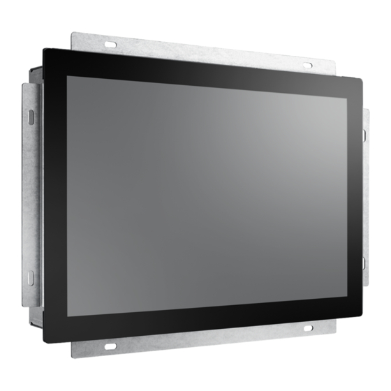
1.1 Introduction UTC-200 series comes with a full range of screen sizes from 7” to 31.5”. With its opened-frame, fanless and low power design, it’s suitable to be embedded into any type of equipment as a HMI such as self-ordering, showroom interactive signage, self-service kiosks, and public service terminals, as well as to support diverse digital retail, hospitality, healthcare, education, entertainment, and information processing applications. -
Page 10: Specification
1.2 Specification 1.2.1 UTC-207 1.2.2 UTC-210... -
Page 11: Utc-220
1.2.3 UTC-220 1.2.4 UTC-232... -
Page 12: Dimensions
1.3 Dimensions 1.3.1 UTC-207 1.3.2 UTC-210... -
Page 13: Utc-220
1.3.3 UTC-220 1.3.4 UTC-232... -
Page 14: Chapter 2
Chapter Quick Start Tour... -
Page 15: Feature Overview
2.1 Feature Overview 2.1.1 UTC-207 Front View Extended Bracket 7” LCD Panel with PCap Touch Rear View M.2 2230 for WiFi Module Main Board (Optional) Speaker (Optional) M.2 2242 for SSD (Optional) DDR3 SO-DIMM... -
Page 16: Utc-210
Coastline I/O Locations DC-In Power Switch USB 3.0 2.1.2 UTC-210 Front View Extended Bracket 10” LCD Panel with PCap Touch... - Page 17 Rear View M.2 2230 for WiFi Module (Optional) Speaker Main Board M.2 2242 for SSD (Optional) DDR3 SO-DIMM Coastline I/O Locations DC-In USB 3.0 Power Switch...
-
Page 18: Utc-220
2.1.3 UTC-220 Front View Unremovable Extended Bracket 21.5” LCD Panel with PCap Touch Rear View 2.5” Storage (Optional) Main Board LED Driving Board... -
Page 19: Utc-232
Main Board Coastline I/O Locations PWR Input HDMI & HDD LED 2.1.4 UTC-232 Front View Unremovable Extended Bracket 32” LCD Panel with PCap Touch... - Page 20 Rear View Main Board Touch Control Board 2.5” Storage (Optional) Power Board with Metal Cover Main Board Coastline I/O Locations PWR Input HDMI & HDD LED...
-
Page 21: Pcm-8523 Apollolake M/B (For Utc-207G/210G)
2.2 UTC-200 M/B Onboard Connectors 2.2.1 PCM-8523 Apollolake M/B (For UTC-207G/210G) SATA LVDS Inverter SATA Power Power Power (12V) COM 2 LAN 2 LAN 1 COM 1 Power DC-In (POE) Switch USB 3.0 (12-24V) -
Page 22: Mio-5350 Apollolake M/B (For Utc-220G/232G)
2.2.2 MIO-5350 Apollolake M/B (For UTC-220G/232G) SATA Power SATA x2 Inverter Power Power Switch USB 2.0 DC Jack HDMI/DP GbE1 & GbE2 USB 3.0 PWR & HDD LED LVDS COM1/COM2/RS-422/RS-485 GPIO HD Audio Mini-PCIe M.2 2242... -
Page 23: Mio-5272 Skylake M/B (For Utc-220F/232F)
2.2.3 MIO-5272 Skylake M/B (For UTC-220F/232F) Inverter SATA Power Power Power Switch LVDS SATA x2 USB 2.0 DC Jack GbE1 & GbE2 USB 3.0 HDMI PWR & HDD LED SMBus COM1 & 2 RS-232/422/485 GPIO HD Audio Mini PCIe 2x USB 2.0 Mini PCIe... -
Page 24: Setup Procedure
After installing the system software, users can set up the Ethernet, XGA, audio, and touchscreen functions. Note! The relevant drivers and utilities are subject to change without notice. Download the latest drivers for UTC series products from the Advantech website at http://support.advantech.com or contact our application... -
Page 25: Chapter 3
Chapter Configuration Upgrade... -
Page 26: Introduction
3.1 Introduction Advantech’s UTC series systems are PC-based computers housed in an aluminum enclosure. To perform system maintenance or hardware upgrades, such as installing an HDD, DRAM, or CompactFlash (A/B models only), simply remove the unit’s rear cover. Warning! Do not remove the rear cover until you have verified that power is not flowing within the device. -
Page 27: Installing A M.2 Ssd (For Utc-207/210)
3.3 Installing a M.2 SSD (For UTC-207/210) Insert the SSD into the M.2 slot located on the upside of the motherboard and fasten the screw. 3.4 Installing a Memory Module for UTC-220/232 Remove the 4 screws from the DRAM memory module heatsink. Turn the memory module over and remove the 2 screws on the underside. -
Page 28: Installing A Memory Module For Utc-207/210
3.5 Installing a Memory Module for UTC-207/210 Install the DRAM module into the SODIMM socket. 3.6 Installing a WiFi Mini PCIe/M.2 Card (Optional) For UTC-220/232, remove the 4 screws holding the heatsink in place. Insert the WLAN card into the mini PCIe slot located on the underside of the motherboard. Connect a coaxial cable to ANT1 and ANT2 ports on the WLAN card. - Page 29 3.7 Installing a Back Cover for UTC-207/210 (Optional) For UTC-207/210, could install the optional back cover. Remove the washer from the DC-in connector and put the cover on the rear side. Fasten the screws at the rear side of the cover. UTC-210 UTC-207...
-
Page 30: Chapter 4
Chapter Mounting Guide... -
Page 31: Introduction
4.1 Introduction With UTC-200 opened-frame design, it’s suitable to be embedded into any type of equipment and chassis with different mounting type. 4.2 Rear Mount Step 1. Make the cutout and add stand off from the rear side of the fixture Step 2 Place the UTC-2xx from the rear side of the fixture and fasten the screws... - Page 33 No part of this publication may be reproduced in any form or by any means, such as electronically, by photocopying, recording, or otherwise, without prior written permission from the publisher. All brand and product names are trademarks or registered trademarks of their respective companies. © Advantech Co., Ltd. 2017...
Need help?
Do you have a question about the UTC-200 Series and is the answer not in the manual?
Questions and answers