Table of Contents
Advertisement
Available languages
Available languages
Quick Links
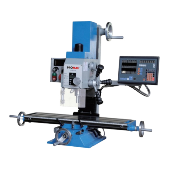
Bohr-Fräsmaschine
P
erceuse fraiseuse
Drilling-milling machine
Schweiz / Suisse
JPW (TOOL) AG
Tämperlistrasse 5
CH-8117 Fällanden Switzerland
www.promac.ch
FX
-820VA
FX-820VA-DRO
France
TOOL France / PROMAC
57, rue du Bois Chaland, Z.I. du Bois Chaland
case postale 2935 FR-91029 Evry Cedex
www.promac.fr
07-2016
Advertisement
Table of Contents

Related Manuals for Promac FX-820VA


Summary of Contents for Promac FX-820VA
- Page 1 Bohr-Fräsmaschine -820VA erceuse fraiseuse FX-820VA-DRO Drilling-milling machine Schweiz / Suisse France JPW (TOOL) AG TOOL France / PROMAC Tämperlistrasse 5 57, rue du Bois Chaland, Z.I. du Bois Chaland CH-8117 Fällanden Switzerland case postale 2935 FR-91029 Evry Cedex www.promac.fr www.promac.ch...
- Page 2 CE‐Conformity Declaration CE‐Konformitätserklärung Déclaration de Conformité CE Product / Produkt / Produit: Drilling‐milling machine Bohr‐Fräsmaschine Perceuse fraiseuse FX‐820VA, FX‐820VA DRO Brand / Marke / Marque: PROMAC Manufacturer / Hersteller / Fabricant: JPW (Tool) AG, Tämperlistrasse 5, CH‐8117 Fällanden Schweiz / Suisse / Switzerland We hereby declare that this product complies with the regulations Wir erklären hiermit, dass dieses Produkt der folgenden Richtlinie entspricht Par la présente, nous déclarons que ce produit correspond aux directives suivantes 2006/42/EC Machinery Directive Maschinenrichtlinie Directive Machines 2014/30/EU Electromagnetic Compatibility Elektromagnetische Verträglichkeit compatibilité électromagnétique designed in consideration of the standards und entspechend folgender zusätzlicher Normen entwickelt wurde et été développé dans le respect des normes complémentaires suivantes EN ISO 12100:2010 EN 13828:2001+A2:2009 EN 60204‐1:2006 ...
-
Page 3: Allgemeine Sicherheitsvorschriften
Allgemeine Sicherheitsvorschriften Hinweis: Die Nicht-Beachtung dieser Anweisungen kann schwere Verletzungen zur Folge haben. Wie bei allen Maschinen sind auch bei dieser Maschine beim Betrieb und der Handhabung maschinentypische Gefahren gegeben. Die aufmerksame Bedienung und der richtige Umgang mit der Maschine verringern wesentlich mögliche Unfallgefahren. - Page 4 Allgemeine Sicherheitsvorschriften 14. Auf Standsicherheit achten. Fussstellung und körperliche Balance immer so halten, dass der sichere Stand gewährleistet ist. 15. Maschine immer in einwandfreiem Zustand halten. Hierzu die Schneidflächen scharf und sauber für die optimale Leistung halten. Die Betriebsanweisung für die Reinigung, das Schmieren und den Wechsel von Anbaugeräten beachten.
-
Page 5: Technische Daten
Technische Daten Modell ..........FX 820VA Bohrleistung Stahl mm ..........20 Fräsleistung Stahl mm ..........16 Motor Volt ............... 230 Motor Kw ............... 0.75 Drehzahlen min-1 ......stufenlos 300-2300 Bohrhub mm ............. 50 Spindelkonus MK ............2 Spindeldurchmesser mm ........... 60 Kopfdrehung L / R ............ - Page 6 Anschluss Ihrer Maschine ans Netz. Der Netzanschluss muss von einem Fachmann erstellt werden. Stückliste der elektrischen Anlage Kurz- Model Funktion Tech. Daten zeichen Motor FX-820VA DC230V/1PH/750W Magnetic Switch ZH-B Emergency Stop Switch Fuse Controller DC 230V Controller DC 230V...
- Page 7 Auspacken Lieferumfang: 1 Bohrfräsmaschine Modell PROMAC FX 820VA, mit digitaler Bohrtiefen- Anzeige 1 Werkzeugkasten, enthält: 1 Spannschraube M10 ........1 Inbusschlüsselsatz 2.5, 3, 4, 5, 6mm 2 T-Nutenschrauben 10mm ......1 Adapter MK II / B 18 1 Gabelschlüssel 17/19mm ......2 Schraubendreher (flach + PH) 1 Austreiber ..........
-
Page 8: Aufstellung Der Maschine
Keine Lackverdünner oder Ähnliches verwenden, da sonst die Lackierung der Maschine zer- stört wird. Darauf achten, dass keine Lösungsmittel oder Fette an Gummi- und Kunststoffteile gelangen. Nach der Reinigung sind alle blanken Teile mit einem Oelfilm des Gleitbahnöls PROMAC 100385 zu überziehen. -
Page 9: Nach Dem Betrieb
Immer Schutzbrille tragen! Maschine abschalten und vom Netz trennen. Werkzeug ausspannen. Maschine reinigen, blanke Teile, Führungen und Spindeln mit dem Gleitbahnöl PROMAC 100385 einölen. Maschine mit Tuch abdecken, um sie vor Staub und Schmutz zu schützen. EIN-/ UND VERSTELLUNG DES MASCHINENKOPFES Um den Maschinenkopf zu heben oder zu senken, die Klemmgriffe lösen (siehe auch Seite 10). - Page 10 Bedienelemente Tischverstellrad längs (A, Fig. 04) Befinden sich links und rechts des Arbeitstisches. Durch drehen verstellt sich der Tisch längsseitig. Tischverstellrad quer (B, Fig. 04) Befindet sich an der Frontseite des Arbeitstisches. Durch drehen verstellt sich der Tisch von der Säule weg oder zu ihr hin.
- Page 11 Bedienelemente Spindelvorschub (J, Fig. 08) Auf der linken Seite des Maschinenkopfes sind die 3 Griffe für den Bohrspindelvorschub. Durch drehen im Gegenuhrzeigersinn wird die Spindel abgesenkt. Eine Rückzugfeder bringt die Spindel wieder automatisch in die Ausgangsstellung. Der Feststellgriff (K, Fig. 08) muss vor der Bedienung gelöst werden.Mit der Skala (L, Fig.
- Page 12 Bedienelemente Elektrische Bedienelemente Start-/Stopschalter (A, Fig.11) Der Schalter ist ein Ein-/Ausschalter mit Notstop- funktion. Die grüne Taste startet die Maschine, mit der roten Ta- ste wird die Maschine abgestellt. Der rote Deckeldrücker ist die Nottaste, welche bei Pro- blemen gedrückt werden muss. Drehzahlwahlschalter (B;...
- Page 13 Bedienelemente Wechseln des Bohr- und Fräswerkzeuges 1. Die Maschine ausschalten und das Netzkabel aus- stecken. 2. Die Schutzkappe (A, Fig, 14) auf dem Kopfoberteil entfernen. 3. Die Spindel (B, Fig, 15) festhalten, die Spannschraube (C, Fig,16) mit einem Gabelschlüssel lösen. 4.
-
Page 14: Ausserordentliche Wartung
Wartung Nachstehend sind die wichtigsten Wartungseingriffe angeführt, die in tägliche, wöchentliche, monatliche und halbjährliche Eingriffe unterteilt werden können. Die Nichteinhaltung der vorgesehenen Arbeiten bedingt einen vorzeitigen Verschleiss und geringere Leistung der Maschine. Tägliche Wartung - Allgemeine Reinigung der Maschine von angefallenen Spänen. - Wiederherstellen des Kühl- und Schmiermittelstandes (Falls Kühlmittelsystem montiert ist). -
Page 15: Consignes Générales De Sécurité
Consignes générales de sécurité Remarque : le non-respect de ces prescriptions peut entraîner des accidents graves. Comme toutes les machines, cette machine présente certains risques caractéristiques inhérents à son fonctionnement et à sa manipulation. L'utilisation attentive et la manipulation correcte de la machine diminuent considérablement les risques d'accidents potentiels. - Page 16 Consignes générales de sécurité 14. Veiller à la stabilité. Toujours conserver la position des pieds et l'équilibre du corps de façon à garantir votre stabilité. 15. Toujours conserver la machine en parfait état. A cet effet, tenir les surfaces de coupe aiguisées et propres pour un rendement optimum.
-
Page 17: Données Techniques
Données techniques Modèle ........... FX 820VA Capacité de perçage dans l'acier, mm ......20 Capacité de fraisage dans l’acier, mm ......16 Moteur à courant continu, volt ........230 Moteur, kW ............. 0.75 Vitesse tpm ......variable 300-1150/600-2300 Descente de broche, mm ........... 50 Cône de broche CM ............. -
Page 18: Schéma Électrique
Le schéma du câblage électrique en 230V, qui est également affiché dans le coffret électrique, contient les indications nécessaires au raccordement correct de la machine au réseau. Liste de composants électriques Model Sigle Fonction Données techniques Pces Motor FX-820VA DC230V/1PH/750W Magnetic Switch ZH-B Emergency Stop Switch Fuse Controller DC 230V Controller DC 230V... - Page 19 Déballage Livrée avec: 1 perceuse-fraiseuse modèle PROMAC FX 820VA , avec affichage digitale de profondeur de perçage 1 coffret outils contenant: 1 tire fond M10 ........1 jeu de clés mâles 2.5, 3, 4, 5, 6mm 2 coulisseaux T 10mm ..... 1 adaptateur CM II / B 18 1 clé...
- Page 20 Avertissement: Attention: n’utilisez pas de diluant pour peinture qui endommagerait la machine. Faites attention à ce que les pièces en caoutchouc ou de matière synthétique ne soient pas en contact avec le dissolvant. Enduisez toutes les parties non-peintes de la machine d’une légère couche d’huile.PROMAC Art. 100385 (vendue en Suisse seulement)
-
Page 21: Mise En Marche
à vide est correct. Si les mesures de sécurité et les conditions normales d’utilisations de la machine sont respectées, sa précision sera assurée pendant de longues années. Graissez la broche avec de l'huile (PROMAC Art. 100385, vendu en Suisse seulement) ou similaire. - Page 22 Eléments de conduite Mouvement longitudinale de la table (A,Fig. 04) De chaque côté de la table se trouvent les manivelles pour déplacer la table longitudinalement. Mouvement transversale de la table (B, Fig. 04 En façade de la table se trouve la manivelle pour le déplacement transversale de la table Fig.
- Page 23 Eléments de conduite Descente de broche (J, Fig. 08) La descente de la broche en perçage s‘obtient en utilisant le cabestant munis de ses trois leviers. En mode perçage il faut que la molette (K) soit déserrer La profondeur de perçage se visualise sur l‘affichage digital dont la machine est équipée.
- Page 24 Eléments de conduite Eléments de conduite électrique Interr up teur MARCHE/ARRET (A, Fig.11) l’interrupteur MARCHE/ARRET sert aussi d‘arrêt d‘urgence. Pour démarrer la machine soulever le couvercle du bloc inter et appuyer sur le bouton Vert. Pour arrêter la machine il suffit d‘appuyer sur le couvercle du bloc inter;...
- Page 25 Eléments de conduite Rempl acement de l’o uti l de perçage ou de fraisage 1. Arrêtez la machine et débranchez la prise du raccordement au réseau.. 2. Dégagez le capot de protection (A, Fig, 14) situé à la tête de la machine. 3.
-
Page 26: Entretien
Entretien Les interventions de maintenance, journalières, hebdomadaires, mensuelles et semi-annuelles, à prévoir, sont indiquées ci-après. Ne pas effectuer régulièrement ces travaux sera une cause d’une usure prématurée de la machine et d’un rendement moins important. Entretien journalier Nettoyage général de la machine de tous les copeaux qui s’y trouvent. Revoir, et compléter si nécessaire, les niveaux de l’huile de graissage et du liquide de coupe (Si la machine est équipée d’un système d’arrosage). -
Page 27: General Safety
General Safety Note: Failure to comply with these instructions can result in serious injury. This machine just like all machines has potential hazards when operating and handling. With correct handling and attention to operate can substantially reduce the risk of accident. There will be inevitable accident to operators If the normal precaution was ignored. -
Page 28: Transporting The Machine
(eg, ear protection). Electrical power supply 1. The models FX-820VA are supplied with a power cord 230v 50Hz. Change of the wire connection has to be done by a professional in accordance with EN60204-1, item 5.3 regulations. -
Page 29: Specifications
Machine Description With the drilling-/milling FX-820VA is a universal machining center which can provide various cutting operations, where usually several different machines were required to complete the work. -
Page 30: Electrical Wire Diagram
Electrical Wire Diagram The electric scheme, 230Volt, which can also found in the control cabinet contains the necessary information for the correct connection of your machine to the power network. The mains connection must be created by a professional. Bill of material for the electrical system Model Abbreviations Function... -
Page 31: Main Controls
Unpacking Shi ppi ng cont ent : 1. Drilling milling machine model FX-820VA, with digital drilling depth indication 2. Tool box contains: 1 clamping screw M10 ........1 Allen key 2.5, 3, 4, 5, 6mm 2 T-bolts 10mm ..........1 Adapter MK II / B 18 1 Wrench 17/19mm ........ -
Page 32: Installation Of The Machine
Note: Do not use paint thinner or similar since it will destroys the painting of the machine. Make sure that get no solvents or grease on rubber and plastic parts. Coat all unpainted parts of the machine with a thin layer of oil. PROMAC Art. 100385 (sold Switzerland only) -
Page 33: After Operation
Switch off the machine and disconnect the power. b) Remove tool. c) Clean the machine, bare parts, guides and spindles with the surface oil PROMAC Oil 100,385 d) Cover machine with cloth to protect it from dust and dirt. - Page 34 Controls Longitudinal movement of the table (A, Fig. 04) On each side of the table are the cranks to move the table longitudinally. Transverse movement of the table (B, Fig. 04) The front of the table is for the crank transverse displacement of the table.
- Page 35 Controls Spindle feed (J, Fig 08) On the left side of the machine head, there is Handles for spindle speed. By turning the handle Counterclockwise direction, the spindle is lowered. one Return spring brings the spindle back automatically in the initial position. The locking handle (K, Fig 08) can be used for setting the drill depth on the scale (L, Fig 08), the desired depth can be set and read here.
-
Page 36: Electrical Controls
Controls Electrical Controls Stop switch (A, Fig.11) The switch is a power switch with emergency stop function. The green button starts the machine with the red button the machine is stopped. The red emergency button which can be used, when problems occured. Speed selector (B, Fig. - Page 37 Controls Changing the drilling and milling tool 1. Turn off the machine and unplug the power cable. 2. The protective cap (A, Fig, 14) on the head shall remove. 3. using a spanner to hold the spindle (B, Fig, 15) clamping screw (C, Fig, 16) .
-
Page 38: Extraordinary Maintenance
Maintenance The most important maintenance procedures are given, in daily, weekly, monthly and semi-annual interventions can be divided. Failure to comply with the proposed work will cause a premature wear and reduced machine performance. Daily maintenance - General cleaning of the machine incurred chips. - (If mounted coolant system) restoring the cooling and lubricating article. - Page 39 Tisch / Pied...
- Page 40 Fuss - Tisch / Pied - Table PM 820201 Kopfschlitten / Support tête PM 820252 Flansch / Support PM 820253 Flansch / Support PM 820202 Schraube / Vis M6x16 PM 820254 Tisch / Table PM 820203 Scheibe / Rondelle M6 PM 820255 Verschraubung / Raccord PM 820204...
- Page 41 Standfuss - Pumpe / Boîtier cdes PM-820A96 Potentiometer / Potentiometer PM-820A78 Elektronikplatte Drehzahl / PM-820A97 Kontaktschütze / Conntacteur Plate electronique vitesse PM-820A98 Flansch / Flasque PM-820A79 Drehgriff / Bouton reglage PM-820A99 Flansch / Flasque PM-820A80 Schraube / Vis PM-820A100 Schraube / Vis PM 820279 Elektronikplatte / Platine alim PM-820A101...
- Page 42 Kopf / Tête...
- Page 43 Kopf / Tête PM 820441 Griff / Molette PM 820401 Scheibe / Circlip PM 820442 Schraube / Vis M5x6 PM 820402 Büchse / Palier PM 820443 Feder / Ressort PM 820403 Feder / Ressort PM 820444 Skalenring / Vernier PM 820404 Seegerring / Circlip 45 PM 820445 Welle / Axe...
-
Page 44: Garantie
Garantie Wir gewähren Ihnen auf den unten eingetragenen Artikeln Garantie auf die Dauer von 24 Monaten ab Laufdatum. Einzige Voraussetzung: die- eingesandten Maschine beigefügt sein. Par ce document nous nous engageons à réparer l‘article mentionné ci- dessous en garantie pendant une période de 24 mois à partir de la date plété...
Need help?
Do you have a question about the FX-820VA and is the answer not in the manual?
Questions and answers