Siemens Simatic ET 200AL Manual
Io-link digital input/digital output module diq 16x24vdc/0,5a 8xm12
Hide thumbs
Also See for Simatic ET 200AL:
- Compact operating instructions (2349 pages) ,
- System manual (2255 pages) ,
- Manual (86 pages)
Table of Contents
Advertisement
Quick Links
Advertisement
Table of Contents

Subscribe to Our Youtube Channel
Related Manuals for Siemens Simatic ET 200AL


Summary of Contents for Siemens Simatic ET 200AL
- Page 2 IO-Link digital input/digital output module DIQ 16x24VDC/0,5A 8xM12 (6ES7143- Preface 5AH00-0BL0) ET 200AL IO-Link I/O modules Documentation Guide SIMATIC Product overview ET 200AL Wiring IO-Link digital input/digital output module Parameters/address space DIQ 16x24VDC/0,5A 8xM12 (6ES7143-5AH00-0BL0) Interrupts/diagnostic alarms Equipment Manual Technical specifications Dimension drawing 08/2021 A5E47926885-AB...
- Page 3 Note the following: WARNING Siemens products may only be used for the applications described in the catalog and in the relevant technical documentation. If products and components from other manufacturers are used, these must be recommended or approved by Siemens. Proper transport, storage, installation, assembly, commissioning, operation and maintenance are required to ensure that the products operate safely and without any problems.
-
Page 4: Preface
Purpose of the documentation This manual supplements the system manual ET 200AL IO-Link (https://support.automation.siemens.com/WW/view/en/109773203). Functions that generally relate to the distributed I/O system ET 200AL IO-Link I/O modules are described there. The information provided in this manual and in the system manual and function manuals supports you in commissioning the ET 200AL IO-Link I/O modules. - Page 5 Siemens' products and solutions undergo continuous development to make them more secure. Siemens strongly recommends that product updates are applied as soon as they are available and that the latest product versions are used. Use of product versions that are no longer supported, and failure to apply the latest updates may increase customers' exposure to cyber threats.
-
Page 6: Table Of Contents
Table of contents Preface ..............................3 ET 200AL IO-Link I/O modules Documentation Guide ................6 Product overview ........................... 9 Properties ..........................9 Operator controls and display elements................12 Wiring ..............................13 Terminal and block diagram ....................13 Pin assignment ........................14 Parameters/address space ........................ -
Page 7: 200Al Io-Link I/O Modules Documentation Guide
ET 200AL IO-Link I/O modules Documentation Guide The documentation for the SIMATIC ET 200AL IO-Link I/O modules is arranged into three areas. This arrangement enables you to access the specific content you require. Basic information The system manual describes in detail the configuration, installation, wiring and commissioning of the distributed I/O system SIMATIC ET 200AL IO-Link I/O modules. - Page 8 You must register once to use the full functionality of "mySupport". You can find "mySupport" on the Internet (https://support.industry.siemens.com/My/ww/en). "mySupport" - Documentation With "mySupport", your personal workspace, you make the best out of your Industry Online Support.
- Page 9 You can find the TIA Selection Tool on the Internet (https://support.industry.siemens.com/cs/ww/en/view/109767888). PRONETA SIEMENS PRONETA (PROFINET network analysis) allows you to analyze the plant network during commissioning. PRONETA has two core functions: • The topology overview automatically scans the PROFINET and all connected components.
-
Page 10: Product Overview
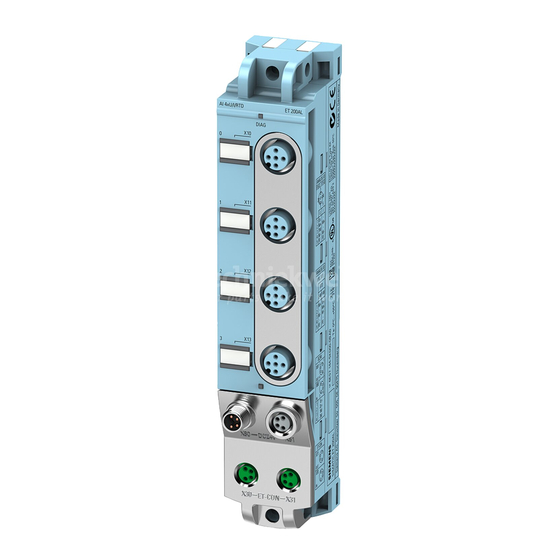
Product overview Properties Article number 6ES7143-5AH00-0BL0 View of the module Figure 2-1 View of the DIQ 16x24VDC/0,5A 8xM12 IO-Link digital input/digital output module IO-Link digital input/digital output module DIQ 16x24VDC/0,5A 8xM12 (6ES7143-5AH00-0BL0) Equipment Manual, 08/2021, A5E47926885-AB... - Page 11 Product overview 2.1 Properties Properties The module has the following technical properties: • 16 digital inputs or digital outputs, depending on configuration and parameter assignment – 16 DIQ signals connected to 2L+ (switched) • M12 sockets for connection of sensors and actuators •...
- Page 12 See also You can find more information on accessories in the Accessories/spare parts section of the ET 200AL distributed I/O system (https://support.industry.siemens.com/cs/us/en/view/89254965) IO-Link I/O modules system manual. IO-Link digital input/digital output module DIQ 16x24VDC/0,5A 8xM12 (6ES7143-5AH00-0BL0) Equipment Manual, 08/2021, A5E47926885-AB...
-
Page 13: Operator Controls And Display Elements
Product overview 2.2 Operator controls and display elements Operator controls and display elements The figure below shows the operator controls and display elements of the DIQ 16x24VDC/0,5A 8xM12 IO-Link digital input/digital output module. ① DIAG: LED display for the diagnostic status ②... -
Page 14: Wiring
Wiring Terminal and block diagram The figure below shows an example of the pin assignment of signal inputs with 2-wire and 3-wire connection and of signal outputs in the configuration modes for digital inputs and outputs. ① Configured as inputs: 2-wire connection Supply voltage 1L+ (non-switched) ②... -
Page 15: Pin Assignment
Wiring 3.2 Pin assignment Pin assignment Pin assignment of the sockets for digital inputs/digital outputs The table below shows the pin assignments of the 8 sockets for the connection of the digital inputs/digital outputs. Table 3- 1 Pin assignment for digital inputs/digital outputs Assignment Front view of the sockets X10 to X17 - sockets for digital inputs/outputs... -
Page 16: Parameters/Address Space
Parameters/address space Parameters The table below shows the parameters for the IO-Link digital input/digital output module DIQ 16x24VDC/0,5A 8xM12. Table 4- 1 Parameters Parameters Value range Default Scope ISDU index ISDU sub- (decimal) index Value (decimal) Diagnostics: Missing load volt- Disable Disable Module... -
Page 17: Explanation Of The Parameters
Parameters/address space 4.2 Explanation of the parameters Explanation of the parameters Diagnostics: Missing load voltage 2L+ Enabling of the diagnostics for missing or insufficient load voltage 2L+. Diagnostics: Short-circuit to ground Enabling of the diagnostics, at short-circuit of an encoder supply or of an output to ground. Freely assignable channel With this parameter, you set whether the channel is to be operated as an input or output. -
Page 18: Address Space
The structure of the IODD is identical for all devices from all manufacturers. The structure of the IODD is always represented in the same manner by the IO-Link Configuration Tool of the master manufacturer (for Siemens, S7-PCT). This ensures that the handling is the same for all IO-Link devices regardless of the manufacturer. -
Page 19: Interrupts/Diagnostic Alarms
Interrupts/diagnostic alarms Status and error displays LED displays The figure below shows the LED displays (status and error displays) of the DIQ 16x24VDC/0,5A 8xM12 IO-Link digital input/digital output module. ① Diagnostic status (DIAG) (red/green) ② Channel status (0 to 15) (green) ③... - Page 20 Interrupts/diagnostic alarms 5.1 Status and error displays Meaning of the LEDs The following tables set out the meaning of the status and error displays. Remedial measures for diagnostic reports can be found in chapter Diagnostics alarms (Page 20). DIAG LED Table 5- 1 Error display of the DIAG LED DIAG LED...
-
Page 21: Interrupts
Interrupts/diagnostic alarms 5.2 Interrupts Interrupts Diagnostic interrupts of the DIQ 16x24VDC/0,5A 8xM12 IO-Link digital input/digital output module. Diagnostic interrupt The digital input/digital output module generates a diagnostic interrupt at the following events: • Short-circuit of an encoder supply to ground, or •... -
Page 22: Technical Specifications
Technical specifications of the DIQ 16x24VDC/0,5A 8xM12 IO-Link digital input/digital output module The following table shows the technical specifications as of the issue date. You can find a data sheet including daily updated technical specifications on the Internet (https://support.industry.siemens.com/cs/de/en/pv/6ES7143-5AH00-0BL0/td?dl=en). Article number 6ES7143-5AH00-0BL0 General information Product type designation DIQ 16X24VDC/0.5A, 8XM12... - Page 23 Technical specifications Article number 6ES7143-5AH00-0BL0 Digital inputs Number of digital inputs 16; Parameterizable as DIQ Input characteristic curve in accordance with IEC 61131, type 3 Number of simultaneously controllable inputs all mounting positions – up to 55 °C, max. Input voltage 24 V •...
- Page 24 Technical specifications Article number 6ES7143-5AH00-0BL0 Switching frequency 100 Hz • with resistive load, max. 0.5 Hz • with inductive load, max. 1 Hz • on lamp load, max. Total current of the outputs • Current per module, max. Cable length 30 m •...
- Page 25 Technical specifications Article number 6ES7143-5AH00-0BL0 Isolation Isolation tested with 707 V DC (type test) Standards, approvals, certificates Suitable for safety-related tripping of standard Yes; From FS01 modules Highest safety class achievable for safety- related tripping of standard modules PL d •...
-
Page 26: Dimension Drawing
Dimension drawing The figure below shows the dimension drawing of the DIQ 16x24VDC/0,5A 8xM12 IO-Link digital input/digital output module in front and side view. Figure A-1 Dimension drawing IO-Link digital input/digital output module DIQ 16x24VDC/0,5A 8xM12 (6ES7143-5AH00-0BL0) Equipment Manual, 08/2021, A5E47926885-AB...
Need help?
Do you have a question about the Simatic ET 200AL and is the answer not in the manual?
Questions and answers