
Related Manuals for Huawei E9000


Summary of Contents for Huawei E9000
-
Page 1: User Guide
E9000 Server V100R001 User Guide Issue Date 2019-11-30 HUAWEI TECHNOLOGIES CO., LTD. - Page 2 Notice The purchased products, services and features are stipulated by the contract made between Huawei and the customer. All or part of the products, services and features described in this document may not be within the purchase scope or the usage scope. Unless otherwise specified in the contract, all statements, information, and recommendations in this document are provided "AS IS"...
-
Page 3: About This Document
Indicates a potentially hazardous situation which, if not avoided, could result in equipment damage, data loss, performance deterioration, or unanticipated results. NOTICE is used to address practices not related to personal injury. Issue 25 (2019-11-30) Copyright © Huawei Technologies Co., Ltd. -
Page 4: Change History
Modified 3.5 Installing Fan Modules. l Modified 3.6 Installing PSUs. l Modified 6.3.3 Backing Up the Configuration Files. l Modified 6.4 Replacing a PSU. l Modified 6.5 Replacing a Fan Module. Issue 25 (2019-11-30) Copyright © Huawei Technologies Co., Ltd. - Page 5 Added 6.7 Replacing the Chassis. l Modified 6.2 Replacing a Compute Node Components. l Modified 6.3 Replacing a Switch Module. 2015-03-31 This issue is the thirteenth official release. Issue 25 (2019-11-30) Copyright © Huawei Technologies Co., Ltd.
- Page 6 This issue is the sixth official release. 2014-01-01 This issue is the fifth official release, and includes the following changes: Modified 3.4 Installing the Chassis describe how to use an installation template to install the chassis. Issue 25 (2019-11-30) Copyright © Huawei Technologies Co., Ltd.
- Page 7 Deleted Architecture. Deleted Technical Specifications from 2.5.2 PSU, 2.5.3 DC PSU, and 2.6.2 Fan Modules, and added the technical specifications to 2.8 Technical Specifications. 2013-01-04 This issue is the first official release. Issue 25 (2019-11-30) Copyright © Huawei Technologies Co., Ltd.
-
Page 8: Table Of Contents
2.7 Security..................................35 2.7.1 Compute Node................................35 2.7.2 Switch Module................................35 2.7.3 Management Module..............................37 2.8 Technical Specifications............................... 39 3 Installing the E9000........................44 3.1 Overview..................................45 3.2 Unpacking the Chassis Packing Case........................... 46 3.3 Removing Components..............................48 3.4 Installing the Chassis..............................54 3.5 Installing Fan Modules.............................. - Page 9 6.5 Replacing a Fan Module.............................139 6.6 Replacing the Chassis Intelligent Display........................142 6.7 Replacing the Chassis..............................148 7 Troubleshooting........................152 8 Expanding the E9000 Capacity....................153 8.1 Precautions for Capacity Expansion...........................153 8.2 Adding Modules................................. 153 8.3 Adding Components of Compute Nodes........................155 Issue 25 (2019-11-30) Copyright ©...
- Page 10 A.2.2 Installation Requirements for the PGND Cable and Power Cables................165 A.2.3 Installation Requirements for Signal Cables......................166 A.3 Unloading and Moving Equipment........................... 167 A.3.1 Transportation Precautions............................. 167 A.3.2 Unloading Equipment............................. 168 A.3.3 Moving Equipment..............................170 Issue 25 (2019-11-30) Copyright © Huawei Technologies Co., Ltd.
-
Page 11: Safety Instructions
Take protective measures against radio interference before operating the device in residential areas. Personal Safety Only personnel certified or authorized by Huawei are allowed to install the hardware. Discontinue any dangerous operations and take protective measures. Report anything that could cause personal injury or equipment damage to a project supervisor. - Page 12 Fasten the strap buckle and ensure that the ESD wrist strap is snug against the skin. Insert the attached ground terminal into the jack on the grounded rack or chassis. Figure 1-3 Wearing a wrist strap Issue 25 (2019-11-30) Copyright © Huawei Technologies Co., Ltd.
- Page 13 Table 1 Maximum weight one person is permitted to carry lists the maximum weight each person is permitted to carry by standards organization. Table 1-1 Maximum handling weight Organization Weight (kg/lb) European Committee for Standardization (CEN) 25/55.13 Issue 25 (2019-11-30) Copyright © Huawei Technologies Co., Ltd.
- Page 14 National Institute for Occupational Safety and Health (NIOSH) 23/50.72 Health and Safety Executive (HSE) 25/55.13 General Administration of Quality Supervision, Inspection and l Men: 15/33.08 Quarantine of the People's Republic of China (AQSIQ) l Women: 10/22.05 Issue 25 (2019-11-30) Copyright © Huawei Technologies Co., Ltd.
-
Page 15: Overview
This section describes the E9000 compute node models, computing density, switching capacity, and switching protocols. The E9000 is a chassis product model developed by Huawei. It is a 12U chassis, which can house E9000 series compute nodes, storage nodes, and resource expansion nodes. -
Page 16: Appearance
An LCD is installed in the lower part of the chassis front panel, which is used to set the basic chassis information and monitor the status of the chassis and components within the chassis. 2.2 Appearance Figure 2-1 Appearance Issue 25 (2019-11-30) Copyright © Huawei Technologies Co., Ltd. - Page 17 E9000 Server User Guide 2 Overview Figure 2-2 Front panel Issue 25 (2019-11-30) Copyright © Huawei Technologies Co., Ltd.
-
Page 18: Indicators
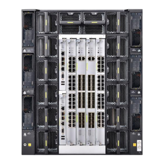
E9000 Server User Guide 2 Overview Figure 2-3 Rear panel 2.3 Indicators Observe the indicator status to view the overall working status. Issue 25 (2019-11-30) Copyright © Huawei Technologies Co., Ltd. - Page 19 Blinking red (at 1 Hz): A major alarm is generated for a component in the chassis. l Blinking red (at 4 Hz): A critical alarm is generated for a component in the chassis. Issue 25 (2019-11-30) Copyright © Huawei Technologies Co., Ltd.
-
Page 20: Physical Structure
For positions and descriptions of the indicators on fan modules, see 2.6.2 Fan Modules. 2.4 Physical Structure This section describes the physical structure and components of the E9000. Hardware Structure Figure 2-5 Hardware structure Issue 25 (2019-11-30) Copyright © Huawei Technologies Co., Ltd. -
Page 21: Front Panel
E9000 Server User Guide 2 Overview Table 2-2 E9000 chassis components Component Description Chassis This is a 12U chassis, providing 8 full-width or 16 half-width compute node slots at the front, and 2 management module slots, 6 PSU slots, 14 fan module slots, and 4 switch or pass- through module slots at the rear. - Page 22 Full-width compute nodes Chassis intelligent display ESN label The front slots of the E9000 are divided into four zones. Only zone 4 supports mixed installation of half- width and full-width compute nodes. Figure 2-7 shows the slot numbers of half-width compute nodes.
- Page 23 Figure 2-9 Slot numbers of the CH220, CH221, CH222, CH220 V3, CH222 V3, and CH221 V5 full-width compute nodes Figure 2-10 shows the positions and slot numbers of child compute nodes in the CH140 V3, CH140. Issue 25 (2019-11-30) Copyright © Huawei Technologies Co., Ltd.
- Page 24 Figure 2-10 Positions and slot numbers of child compute nodes in the CH140 V3, CH140 l A maximum of 16 half-width compute nodes, 8 full-width compute nodes, or 32 child compute nodes can be installed in an E9000 chassis. l The compute nodes must be installed in slots from bottom to top.
-
Page 25: Power Supply System
A jack for inserting the ESD PGND Ground terminal. wrist strap. 2.5 Power Supply System This section describes the principles of the E9000 chassis power supply system, AC PSU, DC PSU, and the PSU configuration policies. Issue 25 (2019-11-30) Copyright © Huawei Technologies Co., Ltd. -
Page 26: Introduction
2.5.1 Introduction Supported PSUs The power supply system for the E9000 chassis consists of six PSUs. PSUs include DC and AC PSUs. When the E9000 is fully configured with PSUs, the power capping value of the chassis is 9000 W to 15000 W. -
Page 27: Ac Psu
PSUs provide short circuit protection. PSUs that support dual input live wires provide bipolar fuse. Appearance Figure 2-12 Appearance The E9000 supports the 2000 W AC Platinum PSUs (EPW2000–12A), 2000 W AC Titanium PSUs (PAC2000S12–TE), and 3000 W AC Platinum PSUs (EPW3000–12A). Issue 25 (2019-11-30) -
Page 28: Dc Psu
This section describes features of DC PSUs. Function The E9000 provides six PSUs in N+1 redundancy, N+N redundancy, or non-redundancy mode. Each PSU centrally supplies power to the chassis and supplies 12.3 V DC power to each slot. Refer to 2.5.4 PSU Configuration Policies... - Page 29 2 Overview Appearance Figure 2-14 Appearance The 2500 W DC PSUs are used. Figure 2-15 shows the nameplate. Figure 2-15 2500 W PSU Indicator Figure 2-16 Indicator on the DC PSU panel Issue 25 (2019-11-30) Copyright © Huawei Technologies Co., Ltd.
-
Page 30: Psu Configuration Policies
A fan module alarm is generated, or a fan module fails. Off: No power is supplied. 2.5.4 PSU Configuration Policies The power consumption of the E9000 varies depending on the system configuration. PSUs are configured based on power consumption. Maximum Power Consumption of Major Components... - Page 31 144 W CX611 144 W CX111 65 W CX210 50 W CX820 128 W CX915 125 W CX916 199.7 W CX220 75 W CX710 180 W CX320 142 W CX620 154 W Issue 25 (2019-11-30) Copyright © Huawei Technologies Co., Ltd.
- Page 32 PSU1, PSU2, PSU3, redundancy PSU4, PSU5 12000 W < P < 15000 W PSU1, PSU2, PSU3, redundancy PSU4, PSU5, PSU6 3000 W < P < 6000 W PSU1, PSU2, PSU4, PSU5 redundancy Issue 25 (2019-11-30) Copyright © Huawei Technologies Co., Ltd.
- Page 33 PSU1, PSU2, PSU3, redundancy PSU4, PSU5, PSU6 2500 W < P < 5000 W PSU1, PSU2, PSU4, PSU5 redundancy 5000 W < P < 7500 W PSU1, PSU2, PSU3, redundancy PSU4, PSU5, PSU6 Issue 25 (2019-11-30) Copyright © Huawei Technologies Co., Ltd.
- Page 34 Table 2-10 Configuration policies for the 2000 W AC PSU (220 V AC to 240 V AC input voltage at 50 Hz or 60 Hz; 2000 W output power) Power Range Redundancy PSU Qty. Recommended Slots Mode P < 2000 W Non- PSU1 redundancy Issue 25 (2019-11-30) Copyright © Huawei Technologies Co., Ltd.
- Page 35 Mode P < 1800 W Non- PSU1 redundancy 1800 W < P < 3600 W Non- PSU1, PSU4 redundancy 3600 W < P < 5400 W Non- PSU1, PSU2, PSU4 redundancy Issue 25 (2019-11-30) Copyright © Huawei Technologies Co., Ltd.
- Page 36 PSU1, PSU2, PSU4 redundancy 2400 W < P < 3200 W Non- PSU1, PSU2, PSU4, PSU5 redundancy 3200 W < P < 4000 W Non- PSU1, PSU2, PSU3, redundancy PSU4, PSU5 Issue 25 (2019-11-30) Copyright © Huawei Technologies Co., Ltd.
- Page 37 10000 W < P < 12500 W Non- PSU1, PSU2, PSU3, redundancy PSU4, PSU5 12500 W < P < 15000 W Non- PSU1, PSU2, PSU3, redundancy PSU4, PSU5, PSU6 P < 2500 W PSU1, PSU4 redundancy Issue 25 (2019-11-30) Copyright © Huawei Technologies Co., Ltd.
- Page 38 3000 W < P < 6000 W PSU1, PSU2, PSU4 redundancy 6000 W < P < 9000 W PSU1, PSU2, PSU4, redundancy PSU5 9000 W < P < 12000 W PSU1, PSU2, PSU3, redundancy PSU4, PSU5 Issue 25 (2019-11-30) Copyright © Huawei Technologies Co., Ltd.
-
Page 39: Heat Dissipation System
E9000 heat dissipation system. Fan Modules and Heat Dissipation Capability The heat dissipation system of the E9000 chassis consists of 14 fan modules. When the E9000 chassis is fully configured with fan modules, the maximum heat dissipation power consumption is as follows: Compute node slot (35°C or 95°F ambient temperature):... - Page 40 Fan modules in the same zone run at the same speed. The speeds of the fans in the three zones are automatically adjusted so that any differences in speed do not exceed 25%. Figure 2-17 Fan module zones Ventilation Channel Figure 2-18 Ventilation channels for front nodes Issue 25 (2019-11-30) Copyright © Huawei Technologies Co., Ltd.
-
Page 41: Fan Modules
Each zone supports N+1 redundancy, ensuring heat dissipation is not affected if a fan unit or module fails. The E9000 chassis uses forced air cooling technology and front-to-rear ventilation channels. This ensures that the air enters the chassis from the front and exits from the rear. - Page 42 Blinking (at 4 Hz): The fan module is abnormally communicating with the MM910. Blinking (at 0.5 Hz): An alarm is generated for the fan module. Off: No power is supplied. Issue 25 (2019-11-30) Copyright © Huawei Technologies Co., Ltd.
-
Page 43: Fan Module Control Modes
(T) in main control mode. Other factors that affect the fan speed are not described here, such as board temperature alarms and component temperatures. Issue 25 (2019-11-30) Copyright © Huawei Technologies Co., Ltd. -
Page 44: Fan Module Configuration Guidelines
This section describes the guidelines for configuring fan modules if a chassis houses different numbers of compute nodes. Fan modules in the chassis must have sufficient heat dissipation capabilities to ensure that the compute nodes and the system operate properly. Issue 25 (2019-11-30) Copyright © Huawei Technologies Co., Ltd. -
Page 45: Security
You can access a compute node with the TPM in a specific way only after authorization and authentication are completed, which ensures user data security in the aspect of hardware. 2.7.2 Switch Module Device Security Hierarchical Command Protection Issue 25 (2019-11-30) Copyright © Huawei Technologies Co., Ltd. - Page 46 MAC address of this packet with blackhole MAC address entries. If the source or destination MAC address of this packet is a blackhole MAC address entry, the switch module discards this packet. Issue 25 (2019-11-30) Copyright © Huawei Technologies Co., Ltd.
-
Page 47: Management Module
Management modules also support SFTP to provide encryption protection for file transfer. SNMP Encrypted Authentication Management modules support encrypted authentication over SNMPv3 and SNMP Trap V3. When management modules are managed by the NMS over SNMP, the encrypted Issue 25 (2019-11-30) Copyright © Huawei Technologies Co., Ltd. - Page 48 Web Service Security The E9000 chassis provides the web service for chassis management over the WebUI. The web service security functions are listed as follows: Automatically converting HTTP requests into HTTPS requests The web service platform automatically converts HTTP requests into HTTPS requests when users access the web service platform using HTTP, enhancing access security.
-
Page 49: Technical Specifications
PSU: 40.5 mm x 126 mm x 285 mm (1.59 in. x 4.96 in. x 11.22 in.) l Fan module: 84 mm x 82 mm x 296.3 mm (3.31 in. x 3.23 in. x 11.67 in.) Issue 25 (2019-11-30) Copyright © Huawei Technologies Co., Ltd. - Page 50 Color Black Weight Net weight: l Empty chassis (including midplane): 70 kg (154.35 lb) l Fully configured chassis: ≤ 230 kg (507.15 lb) Issue 25 (2019-11-30) Copyright © Huawei Technologies Co., Ltd.
- Page 51 (441.00 lb). A cabinet occupies an area of about 1.44 m (15.50 ft. ). The following lists the requirements for the floor bearing capacity based on the number of E9000 chassis in a cabinet: l One E9000 chassis: 347.2 kg/m (0.49 bf/in.
- Page 52 – Half-width slot: 900 W – Full-width slot: 1800 W 40°C (104°F) – Half-width slot: 700 W – Full-width slot: 1400 W l Switch module slot: 280 W l Management module slot: 80 W Issue 25 (2019-11-30) Copyright © Huawei Technologies Co., Ltd.
- Page 53 – 1800 W (for 200 V AC to 220 V AC input) – 2000 W (for 220 V AC to 240 V AC input) l 2500 W DC PSU: 2500 W (for –48 V DC to –60 V DC input) Issue 25 (2019-11-30) Copyright © Huawei Technologies Co., Ltd.
-
Page 54: Installing The E9000
E9000 Server User Guide 3 Installing the E9000 Installing the E9000 This section describes how to remove and install the E9000 chassis and its components and cables. 3.1 Overview 3.2 Unpacking the Chassis Packing Case 3.3 Removing Components 3.4 Installing the Chassis 3.5 Installing Fan Modules... -
Page 55: Overview
Component layout diagram (included in the product documentation bag), which shows the positions for installing compute nodes and switch modules in the E9000 chassis. Cable routing table (provided by onsite delivery personnel), which shows the connections for power cables and signal cables. -
Page 56: Unpacking The Chassis Packing Case
If the packing case is damaged (for example, the packing case is wet or deformed, or the seal or pressure-sensitive tape is unsealed), preserve onsite evidence and report the actual conditions to the supplier or Huawei Technologies Co., Ltd. Step 2 Use a pallet truck to carry the chassis to the equipment room, and remove the pallet truck. - Page 57 Step 4 Check whether the chassis and its components are complete. Table 3-1 Bill of materials Material Quantity Chassis Management module Depending on the contract Switch module Depending on the contract Depending on the contract Fan module Depending on the contract Issue 25 (2019-11-30) Copyright © Huawei Technologies Co., Ltd.
-
Page 58: Removing Components
Place the removed modules in ESD bags or on an ESD floor without stacking them. When all these modules are installed in the E9000 chassis, the total weight is around 100 kg (220.5 lb), which exceeds the allowed maximum weight (68 kg or 149.94 lb) carried by four persons. - Page 59 E9000 Server User Guide 3 Installing the E9000 Figure 3-4 Process for removing the components Procedure Step 1 Determine the components to be removed. Issue 25 (2019-11-30) Copyright © Huawei Technologies Co., Ltd.
- Page 60 A jack for inserting the ESD PGND Ground terminal. wrist strap. Step 2 Remove switch modules. Use a Phillips screwdriver to loosen the two M3 captive screws on a switch module. See (1) in Figure 3-6. Issue 25 (2019-11-30) Copyright © Huawei Technologies Co., Ltd.
- Page 61 Step 2.1 Step 2.5 to remove pass-through modules. Step 4 Remove management modules. Use a Phillips screwdriver to loosen the M3 captive screw on the management module. See (1) in Figure 3-7. Issue 25 (2019-11-30) Copyright © Huawei Technologies Co., Ltd.
- Page 62 Step 5 Remove PSUs. The procedure for removing a DC PSU is the same as that for removing an AC PSU. Press the latch on the PSU. See (1) in Figure 3-8. Issue 25 (2019-11-30) Copyright © Huawei Technologies Co., Ltd.
- Page 63 PSUs. Step 6 Remove fan modules. Hold down the latch on the inner side of the handle. See (1) in Figure 3-9. Figure 3-9 Removing a fan module Issue 25 (2019-11-30) Copyright © Huawei Technologies Co., Ltd.
-
Page 64: Installing The Chassis
If the cabinet depth is less than or equal to 1000 mm or 39.37 in. (such as Huawei N610E-22 cabinet), the space in the rear of the chassis is insufficient for connecting power cables for PDUs. - Page 65 Step 3 Install adjustable guide rails. Then install the stabilizing bracket to stabilize the guide rails and prevent them from being bent. Figure 3-13 Installing adjustable guide rails and the stabilizing bracket Issue 25 (2019-11-30) Copyright © Huawei Technologies Co., Ltd.
- Page 66 21241598, which occupies 1U space. Figure 3-14 Minimum internal width of the cabinet and the distance between the front and rear mounting bars Step 4 Install the chassis. Issue 25 (2019-11-30) Copyright © Huawei Technologies Co., Ltd.
- Page 67 If the position for installing the device is higher than your shoulders, use a stacker to lift the device to prevent personal injury and equipment damage. Figure 3-16 Misoperations ----End Issue 25 (2019-11-30) Copyright © Huawei Technologies Co., Ltd.
-
Page 68: Installing Fan Modules
During operations, wear protective gloves to prevent personal injury. Procedure Step 1 Determine the slots for installing the fan modules. A maximum of 14 fan modules can be installed in an E9000 chassis. Figure 3-17 shows the slot numbers of fan modules. - Page 69 Figure 3-18 Identifier on the air baffle Horizontally insert the fan module into the chassis until the fan module snaps into the chassis. Figure 3-19 Installing a fan module Repeat to install other fan modules. ----End Issue 25 (2019-11-30) Copyright © Huawei Technologies Co., Ltd.
-
Page 70: Installing Psus
Policies. During operations, wear protective gloves to prevent personal injury. Procedure Step 1 Determine the slots for installing the PSUs. A maximum of six PSUs can be installed in an E9000 chassis. Figure 3-20 shows PSU slot numbers. Figure 3-20 PSU slot numbers Step 2 Install PSUs. -
Page 71: Installing Management Modules
During operations, wear protective gloves to prevent personal injury. Procedure Step 1 Determine the slots for installing the management modules. A maximum of two management modules can be installed in an E9000 chassis. Figure 3-22 shows the slot numbers of management modules. - Page 72 Completely close the ejector lever of the management module. See (3) in Figure 3-23. Use a Phillips screwdriver to tighten the M3 captive screw on the management module. See (4) in Figure 3-23. Issue 25 (2019-11-30) Copyright © Huawei Technologies Co., Ltd.
-
Page 73: Installing Switch Modules Or Pass-Through Modules
During operations, wear protective gloves to prevent personal injury. Procedure Step 1 Determine the slots for installing the switch modules or pass-through modules. A maximum of four switch modules or pass-through modules can be installed in an E9000 chassis. Figure 3-24 shows the slot numbers of the switch modules or pass-through modules. -
Page 74: Installing A Half-Width Compute Node
See (4) in Figure 3-25. Repeat to install other switch or pass-through modules. ----End 3.9 Installing a Half-Width Compute Node During operations, wear protective gloves to prevent personal injury. Issue 25 (2019-11-30) Copyright © Huawei Technologies Co., Ltd. - Page 75 When using a box cutter to unpack a packing case, ensure that the knife edge is of a proper protrusion to avoid hurting hands or damaging the device in the packing case. Unpack the half-width compute node, as shown in Figure 3-27. Issue 25 (2019-11-30) Copyright © Huawei Technologies Co., Ltd.
- Page 76 Take out the half-width compute node in its ESD bag and place it on the ESD floor. NO TICE Take a compute node out of its ESD bag only before you install it immediately. Issue 25 (2019-11-30) Copyright © Huawei Technologies Co., Ltd.
- Page 77 E9000 Server User Guide 3 Installing the E9000 Figure 3-28 Proper operations Figure 3-29 Improper operations Step 2 Determine the slot for installing the half-width compute node. Issue 25 (2019-11-30) Copyright © Huawei Technologies Co., Ltd.
- Page 78 Figure 3-30 Slot numbers of the CH121, CH140, CH121 V3, CH121H V3, CH140 V3, CH121 V5 half-width compute nodes l A maximum of 16 half-width compute nodes can be installed in an E9000 chassis. l Half-width compute nodes must be installed in slots from bottom to top. The slot sequence is as follows: slots 1, 9, 2, 10, 3, 11, 4, 12, 5, 13, 6, 14, 7, 15, 8, and 16 Step 3 Remove the filler panel.
- Page 79 Pull the partition board outwards until it clicks into place. See (3) and (4) in Figure 3-32. Press the ejector release button on the half-width compute node. See (1) in Figure 3-33. Issue 25 (2019-11-30) Copyright © Huawei Technologies Co., Ltd.
-
Page 80: Installing A Full-Width Compute Node
3-33. Close the ejector lever on the half-width compute node. See (4) in Figure 3-33. ----End 3.10 Installing a Full-Width Compute Node During operations, wear protective gloves to prevent personal injury. Issue 25 (2019-11-30) Copyright © Huawei Technologies Co., Ltd. - Page 81 When using a box cutter to unpack a packing case, ensure that the knife edge is of a proper protrusion to avoid hurting hands or damaging the device in the packing case. Unpack the full-width compute node. Issue 25 (2019-11-30) Copyright © Huawei Technologies Co., Ltd.
- Page 82 E9000 Server User Guide 3 Installing the E9000 Figure 3-35 Unpacking the full-width compute node Take out the compute node in its ESD bags and place it on the ESD floor. Issue 25 (2019-11-30) Copyright © Huawei Technologies Co., Ltd.
- Page 83 Take a compute node out of its ESD bag only before you install it immediately. Figure 3-36 Proper operations Figure 3-37 Improper operations Step 2 Determine the slot for installing the full-width compute node. Issue 25 (2019-11-30) Copyright © Huawei Technologies Co., Ltd.
- Page 84 Figure 3-39 Slot numbers of the CH220, CH221, CH222, CH220 V3, CH222 V3, CH221 V5 l A maximum of eight full-width compute nodes can be installed in an E9000 chassis. l You are advised to install compute nodes from bottom to up by following the slot numbers in ascending order.
- Page 85 Figure 3-41 Removing the partition board Tilt the partition board rightwards and remove it. See (3) and (4) in Figure 3-41. Press the ejector release buttons on the full-width compute node. See (1) in Figure 3-42. Issue 25 (2019-11-30) Copyright © Huawei Technologies Co., Ltd.
-
Page 86: Installing The Pgnd Cable And Power Cables
To ensure personal and equipment safety, use the recommended power cables. l Power cables can be used only for dedicated server devices, and cannot be used for any other devices. Issue 25 (2019-11-30) Copyright © Huawei Technologies Co., Ltd. - Page 87 Figure 3-43 Process Procedure Step 1 Determine where to connect the PGND cable and power cables. A maximum of six PSUs can be installed in an E9000 chassis. Figure 3-44 shows the positions of the socket of PSU 1 and chassis ground terminal.
- Page 88 3-45. Figure 3-45 Fastening the PGND cable Use a Phillips screwdriver to fasten one end of the PGND cable to the ground terminal on the E9000 chassis. See (2) in Figure 3-45. The cross-sectional area of the PGND cable is greater than or equal to 16 mm (0.025 in.
- Page 89 Step 3 Install power cables. Check the power supply type. – If the AC power supply is used, go to Step 3.2. – If the DC power supply is used, go to Step 3.3. Issue 25 (2019-11-30) Copyright © Huawei Technologies Co., Ltd.
- Page 90 DC PSU, and the O type terminals of the positive electrode to the RTN(+) wiring terminal of the DC PSU. See (1) in Figure 3-50. NO TICE Do not reversely install the power cable. Issue 25 (2019-11-30) Copyright © Huawei Technologies Co., Ltd.
- Page 91 Figure 3-51 Laying out and binding power cables Remove the cut-off ends of the cable ties from the cabinet. ----End Issue 25 (2019-11-30) Copyright © Huawei Technologies Co., Ltd.
-
Page 92: Installing Signal Cables
The CH140, CH140 V3, and CH226 V3 do not have universal connector ports (UCPs). For these compute nodes, multi-port cables are not required. Press the two ejector release buttons on the multi-port cable. See (1) in Figure 3-53. Issue 25 (2019-11-30) Copyright © Huawei Technologies Co., Ltd. - Page 93 Step 2 Connect optical cables. Determine the type and installation position of the optical module based on site requirements. Insert the optical module into the optical port until the optical module clicks into place. Issue 25 (2019-11-30) Copyright © Huawei Technologies Co., Ltd.
- Page 94 Remove the dustproof caps from the optical cable. See (1) in Figure 3-55. Figure 3-55 Connecting an optical cable Insert the optical cable into the optical module. See (2) in Figure 3-55. Issue 25 (2019-11-30) Copyright © Huawei Technologies Co., Ltd.
- Page 95 Lay out the signal cables neatly along the cable organizers, bind the signal cables using cable ties, and use diagonal pliers to trim off the excess ends of cable ties so that there are no rough edges. Issue 25 (2019-11-30) Copyright © Huawei Technologies Co., Ltd.
- Page 96 Figure 3-59 Trimming off the excess ends of cable ties Remove the cut-off ends of the cable ties from the cabinet. ----End Issue 25 (2019-11-30) Copyright © Huawei Technologies Co., Ltd.
-
Page 97: Verifying The Installation
PGND cable and a signal cable meet requirements. Cables are not installed above the heat dissipation holes. Cable ties are evenly spaced and properly fastened. The bending radius of a cable meets the specifications. Issue 25 (2019-11-30) Copyright © Huawei Technologies Co., Ltd. - Page 98 The installed cables do not block the indicators or hinder component replacement. The unused optical cable connectors are covered by protective caps, and the unused optical modules are protected by dustproof covers. Issue 25 (2019-11-30) Copyright © Huawei Technologies Co., Ltd.
-
Page 99: Powering On And Off
You need to power off the chassis before replacing a part due to a chassis or part fault or inspecting the chassis or parts. Procedure Step 1 Ensure that all services and programs on the server are stopped or have been switched over to other devices. Issue 25 (2019-11-30) Copyright © Huawei Technologies Co., Ltd. - Page 100 Step 2 Power off the compute nodes. For details, see their user guides. Step 3 Disconnect the chassis power cables from the external power supply to power off the chassis. ----End Issue 25 (2019-11-30) Copyright © Huawei Technologies Co., Ltd.
-
Page 101: Configuring The E9000
User Guide 5 Configuring the E9000 Configuring the E9000 This section describes the procedures for configuring the E9000 on a local PC for the first time. The initial configuration is performed on the management modules, compute nodes, and switch modules. -
Page 102: Default Information
Login Daemon (SSHD). account prohibite The SSH protocol allows a user to remotely log in to the host execution program and securely manage the host. A user of the rpc service. Issue 25 (2019-11-30) Copyright © Huawei Technologies Co., Ltd. - Page 103 BIOS Setup menus or Ethernet switching planes. For the CX910, CX911, CX912, and CX913 whose software version is V100R001C00 or V100R001C00SPCxxx at the Support > Intelligent Servers > Blade Servers > Issue 25 (2019-11-30) Copyright © Huawei Technologies Co., Ltd.
- Page 104 A BMC user. Huawei Administra Enabled Remote 12#$ or local login – A user who logs in to the Huawei Administra Enabled Local BIOS Setup menu. No user 12#$ login name is used. Issue 25 (2019-11-30) Copyright © Huawei Technologies Co., Ltd.
- Page 105 Note the following about this virtual serial port: l Do not log in to this virtual serial port. l The default password is Huawei#123. l Do not set or change the password of this serial port. Otherwise, some switch module functions fail.
-
Page 106: Configuring Management Modules
You must manually enable this user. 5.3 Configuring Management Modules After installing the MM910, configure it on a local PC to manage components in an E9000 chassis. Configuration Process Step 1 Log in to the MM910 WebUI. Log in to the MM910 WebUI by using the Internet Explorer. -
Page 107: Configuring Compute Nodes
Log in to the MM910 WebUI, and then log in to the real-time desktop of the compute node in remote control mode. Step 6 Configure the RAID controller cards. The compute nodes support the LSI SAS2308 and LSI SAS2208 RAID controller cards. Issue 25 (2019-11-30) Copyright © Huawei Technologies Co., Ltd. -
Page 108: Configuring Switch Modules
SNMP, and Multiple Spanning Tree Protocol (MSTP). ----End For details about how to configure a switch module, see the User Guide and Configuration Guide for the switch module. Issue 25 (2019-11-30) Copyright © Huawei Technologies Co., Ltd. -
Page 109: Parts Replacement
Replace the chassis intelligent display with a new one. 6.7 Replacing the Chassis Replace the chassis with a new one if the chassis midplane is damaged. 6.1 Replacing an MM910 This section describes how to replace an MM910. Issue 25 (2019-11-30) Copyright © Huawei Technologies Co., Ltd. - Page 110 E9000 Server User Guide 6 Parts Replacement Workflow Figure 6-1 Process Procedure Step 1 Determine the MM910 to be replaced. Figure 6-2 shows the MM910 slot numbers. Issue 25 (2019-11-30) Copyright © Huawei Technologies Co., Ltd.
- Page 111 Step 3 Remove the MM910. Remove the cables from the MM910. Use a Phillips screwdriver to loosen the M3 captive screw on the MM910. See (1) in Figure 6-3. Issue 25 (2019-11-30) Copyright © Huawei Technologies Co., Ltd.
- Page 112 Place the removed MM910 into an ESD bag. Step 4 Install a new MM910. Completely open the ejector lever on the MM910. See (1) in Figure 6-4. Figure 6-4 Installing a new MM910 Issue 25 (2019-11-30) Copyright © Huawei Technologies Co., Ltd.
-
Page 113: Replacing A Compute Node And Its Components
The latest version is recommended. For details about the upgrade, see the E9000 Server V100R001 Upgrade Guide. ----End 6.2 Replacing a Compute Node and Its Components This section describes how to replace a compute node and its components. Issue 25 (2019-11-30) Copyright © Huawei Technologies Co., Ltd. -
Page 114: Replacing A Half-Width/Full-Width Compute Node
NO TICE Before powering off the compute node, ensure that service data has been backed up. For details about how to power off a compute node, see the compute node user guide. Issue 25 (2019-11-30) Copyright © Huawei Technologies Co., Ltd. - Page 115 6 Parts Replacement Step 3 Remove the compute node. Press the ejector release button(s) on the compute node. See (1) in Figure 6-6 Figure 6-7. Figure 6-6 Removing a half-width compute node Issue 25 (2019-11-30) Copyright © Huawei Technologies Co., Ltd.
- Page 116 An ESD bag can hold only one compute node. Step 4 Determine whether to replace the components in the compute node. If yes, replace the faulty components. For details, see the CHxxx Compute Node User Guide. Issue 25 (2019-11-30) Copyright © Huawei Technologies Co., Ltd.
- Page 117 The partition board is properly installed when you hear a clicking sound. Figure 6-8 Installing a partition board Press the ejector release button on the half-width compute node. See (1) in Figure 6-9. Issue 25 (2019-11-30) Copyright © Huawei Technologies Co., Ltd.
- Page 118 Press and hold down the hole and push the partition board inwards. See (1) and (2) in Figure 6-10. Move the partition board rightwards and remove it. See (3) and (4) in Figure 6-10 Issue 25 (2019-11-30) Copyright © Huawei Technologies Co., Ltd.
- Page 119 Figure 6-11 Installing a full-width compute node Completely open the ejector levers on the full-width compute node. See (2) in Figure 6-11. Horizontally insert the full-width compute node into the chassis. See (3) in Figure 6-11. Issue 25 (2019-11-30) Copyright © Huawei Technologies Co., Ltd.
-
Page 120: Replacing A Switch Module
If the CLI of the FC switching plane cannot be logged in to, contact Huawei technical support. For details about how to log in to the CLI of the FC switching plane, see "Logging In to the FC Switching Plane"... - Page 121 If PCB Version is VER B, the CPLD software cannot be rolled back to version 0.08 or 0.09. Table 6-1 Preparations Item Name Description Software TFTP server software An example is tftpd32.exe, which is used to remotely connect to a switch module. Issue 25 (2019-11-30) Copyright © Huawei Technologies Co., Ltd.
-
Page 122: Applying For A License (Only For The Cx210 And Cx912)
MX210 and you need to perform different license operations on different types of spare parts: Issue 25 (2019-11-30) Copyright © Huawei Technologies Co., Ltd. - Page 123 20 ports. – If ports 5 to 8 are not in the "(No POD License) Disabled" state, the switch module has 24 ports. Issue 25 (2019-11-30) Copyright © Huawei Technologies Co., Ltd.
-
Page 124: Backing Up The Configuration Files
Step 2 Obtain the CXxxx Switch Module User Guide at Support > Intelligent Servers > Blade Servers > E9000 Chassis. Step 3 Determine the switch module to be replaced. Figure 6-14 shows the switch module slot numbers. Issue 25 (2019-11-30) Copyright © Huawei Technologies Co., Ltd. -
Page 125: Removing Cables And Optical Modules
MX210 or MX220 in the switch module. For details, see step 4 in "Transferring Licenses" of the CXxxx Switch Module User Guide. ----End 6.3.4 Removing Cables and Optical Modules This section describes how to remove cables and optical modules before replacing a switch module. Issue 25 (2019-11-30) Copyright © Huawei Technologies Co., Ltd. - Page 126 Install the dustproof caps for the optical cable. See (3) in Figure 6-16. The methods for removing an optical cable from a 10GE optical port and an 8 Gbit/s FC optical port are the same. Issue 25 (2019-11-30) Copyright © Huawei Technologies Co., Ltd.
- Page 127 Remove the optical cable from the optical module. See (2) and (3) in Figure 6-18. Install dustproof caps for the optical cable and optical module, respectively. See Figure 6-19. Figure 6-19 Installing dustproof caps ----End Issue 25 (2019-11-30) Copyright © Huawei Technologies Co., Ltd.
-
Page 128: Removing And Installing A Switch Module
Step 2 Install a switch module. Completely open the two ejector levers on the switch module and horizontally insert the switch module into the chassis. See (1) and (2) in Figure 6-21. Issue 25 (2019-11-30) Copyright © Huawei Technologies Co., Ltd. -
Page 129: Checking Before Power-On
"Logging In to a Compute Node or a Switch Module over MM910 SOL" in the CXxxx Switch Module User Guide. Perform operations based on the SOL prompt information (if the switch module fails to start properly). Issue 25 (2019-11-30) Copyright © Huawei Technologies Co., Ltd. - Page 130 Step 4 Check the switch modules. If information shown in Figure 6-22 is displayed, upgrade the switch module software to the latest version. For details, see the E9000 Server V100R001 Upgrade Guide. Issue 25 (2019-11-30) Copyright © Huawei Technologies Co., Ltd.
- Page 131 – If the new switch module uses V5 software and the old switch module uses V8 software, upgrade the software of the new switch module to the latest V8 version. For details about how to upgrade the software from V5 to V8, contact Huawei technical support.
-
Page 132: Optional) Upgrading Software By Using U-Boot
MM910 (the ACT indicator of the active MM910 is on) directly or through a LAN. For details, see "Logging In to the MM910 CLI Over a Network Port by Using PuTTY" in the MM910 Management Module V100R001 User Guide. Issue 25 (2019-11-30) Copyright © Huawei Technologies Co., Ltd. - Page 133 STACK port on the active MM910 is also used, connect the network cable to an idle STACK port on an active MM910 in a chassis cascaded with the E9000 chassis. Step 2 Use TFTP or other tools to set up the TFTP server. The TFTP server directory is c:\ftp. Place the switch module upgrade package in this directory.
- Page 134 Figure 6-26 Submenus of the Update from ethernet interface menu Step 5 Enter 4 to select Modify parameters and modify network parameters, including the switch module IP address, TFTP server port IP address, gateway IP address, and network mask. Issue 25 (2019-11-30) Copyright © Huawei Technologies Co., Ltd.
- Page 135 TFTP server, and press Enter to start the software upgrade. After the upgrade is complete, the switch module restarts automatically. ----End Issue 25 (2019-11-30) Copyright © Huawei Technologies Co., Ltd.
-
Page 136: Optional) Deleting The Configuration File Of The V8 Version
Indicates the switching l 0: indicates the onboard plane. GE switching plane. l 1: indicates the 10GE switching plane. l 0: indicates V5. version Indicates the software version. l 1: indicates V8. Issue 25 (2019-11-30) Copyright © Huawei Technologies Co., Ltd. -
Page 137: Restoring The Fc Configuration File
CX220, or the FCoE gateway configuration file of the CX311. If no configuration file is backed up, reconfigure parameters based on customer services. For details, see "Restoring the MXxxx Configuration File by Using Web Tools" or "Restoring the Configuration File" in the Issue 25 (2019-11-30) Copyright © Huawei Technologies Co., Ltd. -
Page 138: Importing And Transferring Licenses (Only For The Cx210 And Cx912)
6 Parts Replacement CXxxx Switch Module User Guide. You can obtain the CXxxx Switch Module User Guide at Support > Intelligent Servers > Blade Servers > E9000 Chassis. Step 2 For the CX912, CX916, CX210, or CX220 switch module, transfer the licenses to the new switch module. - Page 139 20+4 ports (The POD license 20 ports Transfer the POD license. has been activated.) For details, see "Transferring Licenses" in the CXxxx Switch Module User Guide. 20 ports 20 ports License operations are not required. Issue 25 (2019-11-30) Copyright © Huawei Technologies Co., Ltd.
-
Page 140: Installing Cables And Optical Modules
Determine the type and installation position of the optical module based on site requirements. Horizontally insert the optical module into the optical port until the optical module snaps into place. See Figure 6-30. Figure 6-30 Installing an optical module Issue 25 (2019-11-30) Copyright © Huawei Technologies Co., Ltd. - Page 141 Remove the dustproof caps from the optical cable and optical module. See Figure 6-32. Figure 6-32 Removing dustproof caps Insert the optical cable into the optical module. See (1) in Figure 6-33. Issue 25 (2019-11-30) Copyright © Huawei Technologies Co., Ltd.
-
Page 142: Verifying The Switch Module Configuration
The number of failed commands is – The following command output indicates that the configuration fails to be restored: <HUAWEI> display configuration recover-result Warning: Finish configuration recover from flash:/vrpcfg.zip, but some configurations lost. Issue 25 (2019-11-30) Copyright © Huawei Technologies Co., Ltd. -
Page 143: Replacing A Psu
Only one PSU can be replaced at a time. After replacing a PSU, check the indicators on the newly installed PSU. Proceed with the next PSU only after ensuring that the newly installed one is in health status. Workflow Figure 6-34 Process Issue 25 (2019-11-30) Copyright © Huawei Technologies Co., Ltd. - Page 144 – If the AC power supply is used, go to Step 2.2. – If the DC power supply is used, go to Step 2.3. Remove the power cable of the AC PSU. See Figure 6-36. Issue 25 (2019-11-30) Copyright © Huawei Technologies Co., Ltd.
- Page 145 Figure 6-37 Removing the power cable of the DC PSU Remove the power cable of the DC PSU. See (2) in Figure 6-37. Press the latch on the PSU. See (1) in Figure 6-38. Issue 25 (2019-11-30) Copyright © Huawei Technologies Co., Ltd.
- Page 146 – For the PSUs on the left side in the rear view of the chassis, install them with the latches on the upper side. – For the PSUs on the right side in the rear view of the chassis, install them with the latches on the lower side. Issue 25 (2019-11-30) Copyright © Huawei Technologies Co., Ltd.
- Page 147 6-40. Figure 6-40 Installing an AC power cable Go to Step 4.6 after this step is finished. Remove the electrode protection cover of the DC PSU, as shown in Figure 6-41. Issue 25 (2019-11-30) Copyright © Huawei Technologies Co., Ltd.
- Page 148 Connect the other end of the power cable to the PDU according to the power cable connection guidelines. Step 5 Check the indicator status. For details, see 2.5.2 AC PSU 2.5.3 DC PSU. ----End Issue 25 (2019-11-30) Copyright © Huawei Technologies Co., Ltd.
-
Page 149: Replacing A Fan Module
Workflow Figure 6-43 Process Procedure Step 1 Determine the fan module to be replaced. Figure 6-44 shows the slot numbers of the fan modules. Issue 25 (2019-11-30) Copyright © Huawei Technologies Co., Ltd. - Page 150 Figure 6-44 Slot numbers of the fan modules Step 2 Remove the fan module. Hold down the latch on the inner side of the handle. See (1) in Figure 6-45. Figure 6-45 Removing a fan module Issue 25 (2019-11-30) Copyright © Huawei Technologies Co., Ltd.
- Page 151 Figure 6-46 Identifier on the air baffle Horizontally insert the fan module into the chassis until the fan module snaps into the chassis, as shown in Figure 6-47. Issue 25 (2019-11-30) Copyright © Huawei Technologies Co., Ltd.
-
Page 152: Replacing The Chassis Intelligent Display
If the front panel of the chassis intelligent display does not have captive screws or the captive screws cannot be tightened, remove the screws on both sides of the chassis. Issue 25 (2019-11-30) Copyright © Huawei Technologies Co., Ltd. - Page 153 6 Parts Replacement Workflow Figure 6-48 Process Procedure Step 1 Determine the chassis intelligent display to be replaced. Figure 6-49 Locating the chassis intelligent display Step 2 Replace the chassis intelligent display. Issue 25 (2019-11-30) Copyright © Huawei Technologies Co., Ltd.
- Page 154 Horizontally pull the chassis intelligent display out of the chassis. See (2) in Figure 6-50. Place the removed chassis intelligent display into an ESD bag. Horizontally insert the new chassis intelligent display into the chassis. See (1) in Figure 6-51. Issue 25 (2019-11-30) Copyright © Huawei Technologies Co., Ltd.
- Page 155 By now the chassis intelligent display secured by the front captive screws is replaced. Use a Phillips screwdriver to loosen the screws on both sides of the chassis. See (1) in Figure 6-52. Issue 25 (2019-11-30) Copyright © Huawei Technologies Co., Ltd.
- Page 156 Horizontally pull the chassis intelligent display out of the chassis. See (2) in Figure 6-52. Place the removed chassis intelligent display into an ESD bag. 10. Horizontally insert the new chassis intelligent display into the chassis. See (1) in Figure 6-53. Issue 25 (2019-11-30) Copyright © Huawei Technologies Co., Ltd.
- Page 157 15. Upgrade the software of the chassis intelligent display to version 173E or later. Then check whether the chassis intelligent display functions properly. For details about the upgrade, see the E9000 Server V100R001 Upgrade Guide. Issue 25 (2019-11-30) Copyright © Huawei Technologies Co., Ltd.
-
Page 158: Replacing The Chassis
E9000 Server User Guide 6 Parts Replacement – If yes, no further action is required. – If no, contact Huawei technical support engineers. ----End 6.7 Replacing the Chassis Replace the chassis with a new one if the chassis midplane is damaged. - Page 159 Loosen the eight M6 screws and horizontally pull out the chassis from the cabinet, as shown in Figure 2 Removing the chassis. Figure 6-55 Removing the chassis Four persons move the chassis into a packing case or onto a pallet. Issue 25 (2019-11-30) Copyright © Huawei Technologies Co., Ltd.
- Page 160 – If the position for installing the device is higher than your shoulders, use a stacker to lift the device to prevent personal injury and equipment damage. Figure 6-57 Installing the chassis Issue 25 (2019-11-30) Copyright © Huawei Technologies Co., Ltd.
- Page 161 Connect the chassis power cables with the external power supply. Then the chassis, switch modules, management modules, and compute nodes are automatically powered on. Step 8 Check the status of each module by referring to 6 Parts Replacement. ----End Issue 25 (2019-11-30) Copyright © Huawei Technologies Co., Ltd.
-
Page 162: Troubleshooting
User Guide 7 Troubleshooting Troubleshooting For details about troubleshooting, see the Huawei Servers Troubleshooting. It covers the following content: Troubleshooting process Fault information collection Fault diagnosis Firmware and software upgrade Preventive maintenance Issue 25 (2019-11-30) Copyright © Huawei Technologies Co., Ltd. -
Page 163: Expanding The E9000 Capacity
This section describes how to add and upgrade the compute nodes, switch modules, fan modules, and PSUs of the E9000. 8.3 Adding Components of Compute Nodes Add the components of E9000 compute nodes, including CPUs, DIMMs, hard disks, and mezzanine cards. 8.1 Precautions for Capacity Expansion... - Page 164 8 Expanding the E9000 Capacity NO TICE l Before adding switch modules, contact Huawei technical support engineers to determine the networking configuration based on site requirements. l If switch modules are added, the corresponding NICs of the compute nodes must be added.
-
Page 165: Adding Components Of Compute Nodes
----End 8.3 Adding Components of Compute Nodes Add the components of E9000 compute nodes, including CPUs, DIMMs, hard disks, and mezzanine cards. NO TICE Ensure that service data of compute nodes has been backed up before the compute nodes are powered off. - Page 166 E9000 Server User Guide 8 Expanding the E9000 Capacity Procedure Step 1 Determine the types and quantities of the components to be added. Table 8-3 Determining the components to be added Module Type Model Quantity DIMM Hard disk Mezzanine card Step 2 Check the compatibility between the added components and live network components.
- Page 167 V3 Server RAID Controller Card User Guide. If mezzanine cards are added, the corresponding switch modules also need to be added. Contact Huawei technical support to determine the network configuration based on site requirements. Step 5 Install the compute nodes. For details, see 6.2 Replacing a Compute Node and Its...
-
Page 168: A Appendix
Label" in the Engineering Design Document. l Label for the optical cable Equipment Labels Equipment labels include: Chassis label, as shown in Figure A-1. Board label, as shown in Figure A-2. Issue 25 (2019-11-30) Copyright © Huawei Technologies Co., Ltd. - Page 169 Standards Association (CSA), and has the following requirements: Thickness: 0.09 mm (0.0035 in.) Color: chalk white Material: polyester (PET) Temperature range: –29°C to +149°C (–20.2°F to +300.2°F) Handwriting using a greasy pen and laser printing are allowed. Issue 25 (2019-11-30) Copyright © Huawei Technologies Co., Ltd.
-
Page 170: Label Making Specifications
Ensure that the ID plate with the label is on the right side of the cable in vertical cabling, or on top of the cable in horizontal cabling. Ensure that the label is facing outwards. Figure A-4 Attaching labels to the PGND and power cables Issue 25 (2019-11-30) Copyright © Huawei Technologies Co., Ltd. - Page 171 Ensure that the ID plate with the label is on the right side of the cable in vertical cabling, or on top of the cable in horizontal cabling. Ensure that the label is facing outwards. Figure A-6 Attaching a signal cable label (1) Issue 25 (2019-11-30) Copyright © Huawei Technologies Co., Ltd.
-
Page 172: Cable Installation Requirements
Table A-2 Distances between different types of cables (unit: mm/in.) Cable Category 1 Category 2 Category 3 Category 4 Classification Category 1 150/5.91 100/3.94 200/7.87 Category 2 150/5.91 100/3.94 150/5.91 Category 3 100/3.94 100/3.94 150/5.91 Category 4 200/7.87 150/5.91 150/5.91 Issue 25 (2019-11-30) Copyright © Huawei Technologies Co., Ltd. - Page 173 Bind cables outside the cabinet with an interval of 200 mm (7.87 in.) between two adjacent cable ties. Bind cables inside the cabinet with an interval of less than 200 mm (7.87 in.) between two adjacent cable ties. Issue 25 (2019-11-30) Copyright © Huawei Technologies Co., Ltd.
- Page 174 A-3. Table A-3 Bending requirements for signal cables Cable Type Bending Radius (R) Ethernet signal cable R ≥ 2d Optical cable R ≥ 40 mm (1.57 in.); bending angle > 90° Issue 25 (2019-11-30) Copyright © Huawei Technologies Co., Ltd.
-
Page 175: Installation Requirements For The Pgnd Cable And Power Cables
PDU connector and the AC PDC. Use cables with the proper length. If the cables are not long enough, replace the cables. Issue 25 (2019-11-30) Copyright © Huawei Technologies Co., Ltd. -
Page 176: Installation Requirements For Signal Cables
Trim off the excess length of the cabinet PGND cable and power cables. Do not coil up cables. Connect the PGND cable of the E9000 chassis to the nearest ground terminal of the cabinet for an attractive layout. Coil the PGND cable if the excess length is long. -
Page 177: Unloading And Moving Equipment
Transport the equipment in its original packaging. Package heavy, bulky parts (such as chassis and blades) and fragile parts (such as optical modules, PCIe GPUs, and PCIe SSDs) separately. Issue 25 (2019-11-30) Copyright © Huawei Technologies Co., Ltd. -
Page 178: Unloading Equipment
Prepare the following tools before unloading equipment: Crane Rope Forklift Pallet truck Protective gloves Pallet Truck Figure A-13 shows how to unload equipment from a vehicle with a tailgate using a pallet truck. Issue 25 (2019-11-30) Copyright © Huawei Technologies Co., Ltd. - Page 179 Note the following when unloading equipment using a forklift: Obtain certification authorized by the local government or official authorities before operating a forklift. Do not stand in front of the forklift when it is moving. Issue 25 (2019-11-30) Copyright © Huawei Technologies Co., Ltd.
-
Page 180: Moving Equipment
Moving equipment by hand l Weight ≤ 55 kg (121.28 Figure A-28 Figure A-29 l Passage width ≥ 1.5 m (4.92 ft.) l Whether to unpack equipment before moving it: no restriction Issue 25 (2019-11-30) Copyright © Huawei Technologies Co., Ltd. - Page 181 A-16, and Figure A-17 show how to move equipment using a pallet truck. Figure A-15 Moving equipment using a pallet truck (1) Figure A-16 Moving equipment using a pallet truck (2) Issue 25 (2019-11-30) Copyright © Huawei Technologies Co., Ltd.
- Page 182 Figure A-18 Route for moving equipment at a turn Move equipment along a straight line wherever practical, and ensure that the included angle of the yoke and the moving direction is greater than or equal to 120°. Issue 25 (2019-11-30) Copyright © Huawei Technologies Co., Ltd.
- Page 183 Figure A-19 Moving equipment into or out of an elevator Forklift Figure A-20 shows how to move equipment using a forklift. Figure A-20 Moving equipment using a forklift Note the following when moving equipment using a forklift: Issue 25 (2019-11-30) Copyright © Huawei Technologies Co., Ltd.
- Page 184 Slow down the forklift before making a turn. When making a turn, pull equipment to move along the outer side of the passage center line (to increase the radius of the turn), as shown in Figure A-23. Issue 25 (2019-11-30) Copyright © Huawei Technologies Co., Ltd.
- Page 185 During transportation, prevent equipment from swaying. If a wheel is stopped by cable ties or screws, remove the obstructions. Flatbed Dolly Figure A-24 Figure A-25 show how to move equipment using a flatbed dolly. Figure A-24 Moving equipment using a flatbed dolly (1) Issue 25 (2019-11-30) Copyright © Huawei Technologies Co., Ltd.
- Page 186 (to increase the radius of the turn), as shown in Figure A-26. Figure A-26 Route for moving equipment at a turn Issue 25 (2019-11-30) Copyright © Huawei Technologies Co., Ltd.
- Page 187 Comply with local laws or regulations for the maximum load per person. Figure A-28 shows how to move equipment by one person. Figure A-29 shows how to move equipment by two persons. Issue 25 (2019-11-30) Copyright © Huawei Technologies Co., Ltd.
- Page 188 Figure A-29 Moving equipment by two persons Note the following when moving equipment by hand: Wear clean protective gloves, work clothes, safety helmet, and work shoes, as shown in Figure A-30. Issue 25 (2019-11-30) Copyright © Huawei Technologies Co., Ltd.
- Page 189 (MAWL) allowed by local laws or regulations. – Arrange for enough personnel to move equipment. If an accident occurs during transportation, protect yourself first and then the equipment. Issue 25 (2019-11-30) Copyright © Huawei Technologies Co., Ltd.
Need help?
Do you have a question about the E9000 and is the answer not in the manual?
Questions and answers