Huawei FusionModule2000 Installation Manual
Smart modular data center
Hide thumbs
Also See for FusionModule2000:
- Installation manual (271 pages) ,
- Product description (217 pages) ,
- Maintenance manual (144 pages)

Related Manuals for Huawei FusionModule2000


Summary of Contents for Huawei FusionModule2000
- Page 1 FusionModule2000 Smart Modular Data Center V500R002C03 Installation Guide Issue Date 2018-03-31 HUAWEI TECHNOLOGIES CO., LTD.
- Page 2 Notice The purchased products, services and features are stipulated by the contract made between Huawei and the customer. All or part of the products, services and features described in this document may not be within the purchase scope or the usage scope. Unless otherwise specified in the contract, all statements, information, and recommendations in this document are provided "AS IS"...
-
Page 3: About This Document
Purpose This document describes the site requirements for installing the FusionModule2000 smart modular data center (FusionModule2000 for short) as well as the methods for installing cabinets, devices, and cables, providing installation guidance and technical support for onsite installation personnel and technical support engineers. - Page 4 FusionModule2000 Smart Modular Data Center Installation Guide About This Document Symbol Description NOTE is used to address information not related to personal injury, equipment damage, or environment deterioration. Change History Changes between document issues are cumulative. The latest document issue contains all updates made in previous issues.
-
Page 5: Table Of Contents
FusionModule2000 Smart Modular Data Center Installation Guide Contents Contents About This Document ........................ii 1 Safety Precautions ......................... 1 1.1 General Safety Precautions ............................1 1.2 Electrical Safety ................................2 1.3 Battery Safety ................................4 1.4 Mechanical Safety ................................ 6 1.5 Others.................................... - Page 6 FusionModule2000 Smart Modular Data Center Installation Guide Contents 4.3.3 Installing Bases with Fixed Dimensions ........................50 4.4 Connecting Base Ground Cables ..........................52 5 Installing the PDC ........................54 5.1 Moving the PDC ................................. 54 5.2 Installing a Tail Frame ..............................56 5.3 (Optional) Installing a Top Frame ..........................
- Page 7 FusionModule2000 Smart Modular Data Center Installation Guide Contents 10.5.2 Installing Sliding Doors (Dual-Row 2200 mm) ....................121 10.5.3 Installing Revolving Doors (Single-Row and Dual-Row 2000 mm) ..............128 10.5.4 Installing Revolving Doors (Single-Row and Dual-Row 2200 mm) ..............140 10.6 Attaching Cabinet Labels ............................148 11 Installing Cable Troughs and Cable Trays ................
- Page 8 FusionModule2000 Smart Modular Data Center Installation Guide Contents 15.4.6 (Optional) Installing a Revolving Door Magnetic Lock ..................204 15.4.7 (Optional) Installing a Sliding Door Magnetic Lock ................... 208 15.4.8 Installing a Button ..............................210 15.4.9 Installing a Monitoring Device on the Pad Mounting Kit ..................211 15.4.9.1 (Optional) Installing a Fingerprint and Card Reader ..................
- Page 9 FusionModule2000 Smart Modular Data Center Installation Guide Contents 17.6 Cable Routes for the Single-Row Aisle Containment Scenario (Smart Busway) ........... 277 17.7 (Optional) Cable Routing for the Air Conditioner PDB ..................278 17.8 Connecting Cables to the Power Supply and Distribution System ................. 278 17.8.1 Connecting Cables to Power Supply and Distribution Devices ................
-
Page 10: Safety Precautions
Personal Requirements Only trained and qualified personnel are allowed to install, operate, and maintain Huawei equipment, and they must understand basic safety precautions to avoid hazards. ... -
Page 11: Electrical Safety
Only trained and qualified personnel are allowed to remove safety facilities and inspect the equipment. Only personnel certified or authorized by Huawei are allowed to replace or change the equipment or components (including software). Installation personnel must report faults or errors that might cause serious safety issues to related owners. - Page 12 FusionModule2000 Smart Modular Data Center Installation Guide 1 Safety Precautions Devices are powered by high-voltage power source. Direct or indirect contact (through damp objects) with the power source may result in serious injury. Non-standard and improper operations under high voltage may result in fire and electric shocks.
-
Page 13: Battery Safety
FusionModule2000 Smart Modular Data Center Installation Guide 1 Safety Precautions Figure 1-1 Putting on an ESD wrist strap Neutral-Ground Voltage It is recommended that the three-phase loads be equalized and the neutral-ground voltage be kept at less than 2 V to meet power distribution requirements. - Page 14 FusionModule2000 Smart Modular Data Center Installation Guide 1 Safety Precautions When handling a battery, ensure that its electrodes are upward. Placing the battery upside down or tilting the battery is prohibited. Switch off the power supply during installation and maintenance.
-
Page 15: Mechanical Safety
FusionModule2000 Smart Modular Data Center Installation Guide 1 Safety Precautions NaHCO When using substances to neutralize and absorb electrolytes, strictly follow the guidelines provided by the battery manufacturer. If your body comes in contact with the leaked electrolyte, wash with clean water immediately and seek medical advice if the situation is serious. -
Page 16: Others
FusionModule2000 Smart Modular Data Center Installation Guide 1 Safety Precautions Be careful to prevent injury when moving heavy objects. To prevent injury, when moving the chassis outwards, be aware of unfixed or heavy objects on the chassis. ... -
Page 17: Installation Preparations
FusionModule2000 Smart Modular Data Center Installation Guide 2 Installation Preparations Installation Preparations 2.1 Precautions for Transportation and Placing Precautions for Transportation Only trained personnel are allowed to move the cabinet. Use a pallet truck to transport the cabinet secured to a wooden support to the installation position. Insert the forks of the pallet truck in the middle position to ensure balance. -
Page 18: Unpacking And Acceptance
Step 1 Unpack the carton labeled Contain Packing List and take out the Packing List. Step 2 Check all items against the Packing List. Step 3 If an item is incorrect or missing, contact Huawei technical support. Step 4 If any item is damaged, fill in the Cargo Replacement Application Form and report it. -
Page 19: Installation Environment Check
FusionModule2000 Smart Modular Data Center Installation Guide 2 Installation Preparations Step 5 Sign on the Packing List with the customer after verifying that all required items are delivered. Step 6 Store the items properly. ----End Follow-up Procedure Put the items to be installed immediately onto an ESD surface, such as a polyethylene (PE) bag or an expandable polyethylene (EPE) foam. - Page 20 FusionModule2000 Smart Modular Data Center Installation Guide 2 Installation Preparations Check Item Criteria Check Result □ Passed □ Failed Floor levelness Allowed deviation: 2000± 3 mm □ Passed □ Failed Elevator Elevator load bearing capacity > 1.5 Elevator internal size: height > 2.4 m or depth >...
-
Page 21: Site Requirements
FusionModule2000 Smart Modular Data Center Installation Guide 2 Installation Preparations If any of the requirements is not met, contact Huawei technical support. 2.4 Site Requirements Figure 2-3 Single-row scenario Figure 2-4 Dual-row scenario Issue 02 (2018-03-31) Huawei Proprietary and Confidential... -
Page 22: Documentation Preparations
FusionModule2000 Smart Modular Data Center Installation Guide 2 Installation Preparations 2.5 Documentation Preparations Before installation, prepare the following documents in addition to this document. Table 2-2 Preparing installation documents System Component Document Category Power Precision power PDU8000 Modular Precision PDC Quick Guide... -
Page 23: Tools And Instruments
FusionModule2000 Smart Modular Data Center Installation Guide 2 Installation Preparations System Component Document Category Cable trays Indoor Cable Tray Installation Guide The ECC800 and NetEco versions depend on the version in use. Click on the ECC800 and the NetEco WebUI to obtain the ECC800 and NetEco versions. - Page 24 FusionModule2000 Smart Modular Data Center Installation Guide 2 Installation Preparations Name, Specifications, and Appearance Hand drill (Φ3, Hammer drill (Φ16 Electric screwdriver Heat gun Φ3.7, Φ4, Φ4.5, Φ5, drill bit) Φ6, Φ10, and Φ12 drill bits) Laser locator Utility knife...
- Page 25 FusionModule2000 Smart Modular Data Center Installation Guide 2 Installation Preparations Name, Specifications, and Appearance Claw hammer Vacuum cleaner Hacksaw Handsaw Right angle Heat shrink tubing Network cable tester Rubber mallet Adjustable socket Flashlight Clamp meter screwdriver NOTE This table may not list some tools required at specific sites. Onsite installation personnel and technical support personnel should prepare tools based on site requirements.
- Page 26 FusionModule2000 Smart Modular Data Center Installation Guide 2 Installation Preparations Tool Appearance, Specifications, and Name Oxygen Acetylene Hot melt device (for Nitrogen rigid water pipes) Pressure gauge (2 Leather hose (5 Pipe bender Pipe expander PCS) PCS) Vacuum pump Thermocouple...
-
Page 27: Personnel Requirements
Only trained and qualified personnel who fully understand basic safety precautions are allowed to install and operate a modular data center. Huawei will not be liable for any consequence caused by the violation of this document. The requirements are as follows: ... -
Page 28: Power Supply And Distribution Cabinet Scenario (Dual-Row)
FusionModule2000 Smart Modular Data Center Installation Guide 2 Installation Preparations The floor plan and exterior diagrams only indicate the relative positions of components. For the detailed installation position, see the engineering layout diagram and actual objects. The PDC in smart module A is an integrated UPS, with batteries deployed inside the aisle containment. -
Page 29: Power Supply And Distribution Cabinet Scenario (Single-Row)
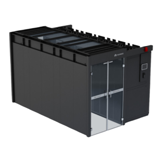
FusionModule2000 Smart Modular Data Center Installation Guide 2 Installation Preparations Figure 2-6 Exterior of the dual-row aisle containment (1) End door (2) Flat or rotating skylight (3) For the alarm beacon (4) For the pad (5) Control skylight (6) Cable trough... -
Page 30: Smart Busway Scenario (Dual-Row)
FusionModule2000 Smart Modular Data Center Installation Guide 2 Installation Preparations Figure 2-8 Exterior of the single-row aisle containment (1) End door (2) Flat or rotating skylight (3) Control skylight (4) Cable trough (5) Smart ETH gateway (6) Cabinet (7) For the alarm beacon... -
Page 31: Smart Busway Scenario (Single-Row)
FusionModule2000 Smart Modular Data Center Installation Guide 2 Installation Preparations Figure 2-10 Exterior of the dual-row aisle containment (1) General input unit (2) Control skylight (3) For the alarm beacon (4) Power distribution unit (5) Busbar trunking unit (6) Flat or rotating skylight... - Page 32 FusionModule2000 Smart Modular Data Center Installation Guide 2 Installation Preparations Figure 2-12 Exterior of the single-row aisle containment (1) General input unit (2) Control skylight (3) For the alarm beacon (4) Power distribution unit (5) Busbar trunking unit (6) Flat or rotating skylight...
-
Page 33: Smart Module Layout Requirements
FusionModule2000 Smart Modular Data Center Installation Guide 3 Smart Module Layout Requirements Smart Module Layout Requirements 3.1 Layout Requirements for Standard Dual-Row Aisle Containment Prerequisites The floor levelness meets engineering requirements (levelness tolerance: ± 3 mm). Procedure Step 1 Determine the installation position for the smart module based on the onsite engineering layout diagram. -
Page 34: Layout Requirements For Standard Single-Row Aisle Containment
FusionModule2000 Smart Modular Data Center Installation Guide 3 Smart Module Layout Requirements Figure 3-1 Using a laser locator for positioning (dual-row aisle containment) (1) Marking-off template (2) Aisle containment (3) Laser locator Step 4 Use a measuring tape to measure the aisle distance and mark the position for the end cabinet in the other row in the same way. - Page 35 FusionModule2000 Smart Modular Data Center Installation Guide 3 Smart Module Layout Requirements Step 2 Use a laser locator to mark two lines that are perpendicular to each other in a corner of the planned installation position. If no laser locator is available, use a right angle and thin rope to mark the two perpendicular lines.
-
Page 36: Layout Requirements For Dual-Row Aisle Containment With A Column
FusionModule2000 Smart Modular Data Center Installation Guide 3 Smart Module Layout Requirements 3.3 Layout Requirements for Dual-Row Aisle Containment with a Column This section describes the column position in the scenario with a column relative to the adjustable skylight, sealing plates, and cable trays. - Page 37 FusionModule2000 Smart Modular Data Center Installation Guide 3 Smart Module Layout Requirements Figure 3-4 Column in the aisle containment (A < 800 mm) Cabinet places on both sides of the column are left blank and sealed by sealing plates. Directions of...
- Page 38 FusionModule2000 Smart Modular Data Center Installation Guide 3 Smart Module Layout Requirements Figure 3-5 Column occupying part of a cabinet place (A < 800 mm and B ≥ 400 mm) Cabinet places on both sides of the column are left blank and sealed by sealing plates. Directions of...
- Page 39 FusionModule2000 Smart Modular Data Center Installation Guide 3 Smart Module Layout Requirements Figure 3-6 Column occupying part of a cabinet place (A ≥ 800 mm and B ≥ 400 mm) Cabinet places on both sides of the column are left blank and sealed by sealing plates. Directions of...
- Page 40 FusionModule2000 Smart Modular Data Center Installation Guide 3 Smart Module Layout Requirements Figure 3-7 Column in a row of cabinets (A < 70 mm and B ≥ 400 mm) Cabinet places on the column side are left blank and sealed by sealing plates. Directions of the...
- Page 41 FusionModule2000 Smart Modular Data Center Installation Guide 3 Smart Module Layout Requirements Figure 3-8 Column in a row of cabinets (A ≥ 70 mm and B ≥ 0 mm) Seal both sides of the column using sealing plates. Directions of the concave sides of the sealing...
-
Page 42: Layout Requirements For Single-Row Aisle Containment With A Column
FusionModule2000 Smart Modular Data Center Installation Guide 3 Smart Module Layout Requirements 3.4 Layout Requirements for Single-Row Aisle Containment with a Column This section describes the column position in the scenario with a column relative to the adjustable skylight, sealing plates, and cable trays. - Page 43 FusionModule2000 Smart Modular Data Center Installation Guide 3 Smart Module Layout Requirements Figure 3-10 Column in the aisle containment (A < 800 mm) Cabinet places on the column side are left blank and sealed by sealing plates. Directions of the...
- Page 44 FusionModule2000 Smart Modular Data Center Installation Guide 3 Smart Module Layout Requirements Figure 3-11 Column occupying part of a cabinet place (A < 800 mm and B ≥ 400 mm) Cabinet places on the column side are left blank and sealed by sealing plates. Directions of the...
- Page 45 FusionModule2000 Smart Modular Data Center Installation Guide 3 Smart Module Layout Requirements Figure 3-12 Column occupying part of a cabinet place (A ≥ 800 mm and B ≥ 400 mm) Cabinet places on the column side are left blank and sealed by sealing plates. Directions of the...
- Page 46 FusionModule2000 Smart Modular Data Center Installation Guide 3 Smart Module Layout Requirements Figure 3-13 Column in a row of cabinets (A < 70 mm and B ≥ 400 mm) Cabinet places on the column side are left blank and sealed by sealing plates. Directions of the...
- Page 47 FusionModule2000 Smart Modular Data Center Installation Guide 3 Smart Module Layout Requirements Figure 3-14 Column in a row of cabinets (A ≥ 70 mm and B ≥ 0 mm) Seal both sides of the column using sealing plates. Directions of the concave sides of the sealing...
- Page 48 FusionModule2000 Smart Modular Data Center Installation Guide 3 Smart Module Layout Requirements Issue 02 (2018-03-31) Huawei Proprietary and Confidential Copyright © Huawei Technologies Co., Ltd.
-
Page 49: Optional) Installing Bases
If there are bases, install air conditioners first. If there are no bases, install cabinets from the end cabinet in sequence. If you do not use the bases provided by Huawei, design the load bearing requirements for bases according to the service plan. ... -
Page 50: Installing Bases With Adjustable Dimensions
FusionModule2000 Smart Modular Data Center Installation Guide 4 (Optional) Installing Bases Figure 4-1 Single-row base layout (unit: mm) Figure 4-2 Dual-row base layout (unit: mm) 4.2 Installing Bases with Adjustable Dimensions Context A base with adjustable dimensions can be 300 mm, 600 mm, or 800 mm wide, and applies to the PDC, battery cabinet, IT cabinet, network cabinet, and air conditioner cabinet. - Page 51 FusionModule2000 Smart Modular Data Center Installation Guide 4 (Optional) Installing Bases Table 4-1 Specifications of bases with adjustable dimensions Type Dimensions Height (adjustable): 270–410 mm; depth 300 mm wide base (adjustable): 1000 mm, 1100 mm, or 1200 Height (adjustable): 410–700 mm; depth...
- Page 52 FusionModule2000 Smart Modular Data Center Installation Guide 4 (Optional) Installing Bases Figure 4-3 Measuring the ESD floor height Adjust the base height to H and tighten the height locking bolts on the feet. Figure 4-4 Tightening height locking bolts Step 2 Assemble the base.
- Page 53 FusionModule2000 Smart Modular Data Center Installation Guide 4 (Optional) Installing Bases Figure 4-5 Assembling a base Assemble the telescopic rod and the base, and then tighten the bolt assembly. Step 3 Use a right angle to position the end cabinet base, and ensure that the outline of the upper surface of the base aligns with the cabinet bottom outline on the floor.
- Page 54 FusionModule2000 Smart Modular Data Center Installation Guide 4 (Optional) Installing Bases Figure 4-7 Positioning Step 7 Move away the base, use a hammer drill with a φ16 drill bit to drill holes to a depth of 52–60 mm at the installation position, and install expansion sleeves.
-
Page 55: Installing Bases With Fixed Dimensions
FusionModule2000 Smart Modular Data Center Installation Guide 4 (Optional) Installing Bases Step 12 Connect bases using connecting plates, as shown by (1) in Figure 4-9. Figure 4-9 Connecting bases Step 13 Screw the floor holder to the base, as shown by (2) in Figure 4-9. - Page 56 FusionModule2000 Smart Modular Data Center Installation Guide 4 (Optional) Installing Bases Figure 4-10 300 mm wide air conditioner base Preparations Tool: Phillips screwdriver Material: air conditioner base (300 mm wide) Document: base installation position diagram Procedure Step 1 Remove the four M6 screws from adjustable feet and set them aside.
-
Page 57: Optional) Adjusting Adjustable Feet Of Air Conditioner And Pdc Bases (600 Mm Wide)
FusionModule2000 Smart Modular Data Center Installation Guide 4 (Optional) Installing Bases Move the adjustable feet of the air conditioner base to the cabinet front (close to the front door of the cabinet). Step 3 Secure the adjustable feet using the four M6 screws removed before. - Page 58 FusionModule2000 Smart Modular Data Center Installation Guide 4 (Optional) Installing Bases Figure 4-13 600 mm wide adjustable base (1) Used for a PDC in a cold aisle (2) Used for an air conditioner in a cold containment or an air conditioner in a hot...
-
Page 59: Installing Bases With Fixed Dimensions
FusionModule2000 Smart Modular Data Center Installation Guide 4 (Optional) Installing Bases Move the adjustable feet of the air conditioner base to the cabinet front (close to the front door of the cabinet). Move the adjustable feet of the PDC base to the cabinet rear (close to the rear door of the cabinet). - Page 60 FusionModule2000 Smart Modular Data Center Installation Guide 4 (Optional) Installing Bases Procedure Step 1 Place a base with fixed dimensions on the concrete floor based on the base installation position diagram. When deploying the base, place the side marked FRONT facing the aisle containment.
-
Page 61: Connecting Base Ground Cables
FusionModule2000 Smart Modular Data Center Installation Guide 4 (Optional) Installing Bases Figure 4-17 Securing adjacent bases ----End 4.4 Connecting Base Ground Cables Prerequisites Bases have been installed. Context There are two solutions of grounding bases: Connect the base ground point to the general ground bar of the equipment room. - Page 62 FusionModule2000 Smart Modular Data Center Installation Guide 4 (Optional) Installing Bases Procedure Step 1 Connect one end of the base ground cable to any of the base ground points, and connect the other end to the general ground bar of the equipment room.
-
Page 63: Installing The Pdc
FusionModule2000 Smart Modular Data Center Installation Guide 5 Installing the PDC Installing the PDC 5.1 Moving the PDC Context Only trained personnel are allowed to move the PDC. Use a forklift truck to transport the PDC box secured to a wooden support to the installation position. - Page 64 If any damage is found, notify the carrier immediately. Check that the fittings comply with the packing list. If some fittings are missing or do not comply with the packing list, record the information and contact your local Huawei office immediately.
-
Page 65: Installing A Tail Frame
FusionModule2000 Smart Modular Data Center Installation Guide 5 Installing the PDC Figure 5-2 Raising the leveling feet Step 7 Move the PDC over its castors to the installation position. If there are bases, place the PDC on the base. ----End 5.2 Installing a Tail Frame... - Page 66 FusionModule2000 Smart Modular Data Center Installation Guide 5 Installing the PDC Figure 5-3 Installing a top frame Step 2 Place the top frame, the side with FRONT facing upwards and the end near FRONT facing the cabinet front door, as shown by (2) in Figure 5-3.
-
Page 67: Installing The Network Cabinet, It Cabinet, And Battery Cabinet
FusionModule2000 Smart Modular Data Center 6 Installing the Network Cabinet, IT Cabinet, and Battery Installation Guide Cabinet Installing the Network Cabinet, IT Cabinet, and Battery Cabinet 6.1 Moving the Network Cabinet, IT Cabinet, and Battery Cabinet Preparations Tool: adjustable wrench Procedure Step 1 Move the cabinet to the planned installation position. -
Page 68: Optional) Installing Side Plates For It Cabinets
FusionModule2000 Smart Modular Data Center 6 Installing the Network Cabinet, IT Cabinet, and Battery Installation Guide Cabinet Figure 6-1 Removing screws Step 3 Remove the cabinet from the pallet and place the cabinet in the installation position. If there is a base, place the cabinet on the base. - Page 69 FusionModule2000 Smart Modular Data Center 6 Installing the Network Cabinet, IT Cabinet, and Battery Installation Guide Cabinet Figure 6-2 Installing a floating nut Step 2 (Optional) Remove side plates based on the labels on the side plates to be adjusted.
-
Page 70: Optional) Taking Out Rpdu Cables
FusionModule2000 Smart Modular Data Center 6 Installing the Network Cabinet, IT Cabinet, and Battery Installation Guide Cabinet 6.3 (Optional) Taking out rPDU Cables Preparations Tools: diagonal pliers Procedure Step 1 Remove the rodent-proof mesh on the top of the rPDU in a cabinet, and take out the rPDU cables from the top. - Page 71 FusionModule2000 Smart Modular Data Center 6 Installing the Network Cabinet, IT Cabinet, and Battery Installation Guide Cabinet Figure 6-4 Taking out industrial connectors Step 2 Lay out the industrial connectors and cables on the cabinet top, and reinstall the rodent-proof mesh.
-
Page 72: Optional) Adjusting Battery Cabinet Side Plates
FusionModule2000 Smart Modular Data Center 6 Installing the Network Cabinet, IT Cabinet, and Battery Installation Guide Cabinet Follow-up Procedure Before connecting the power plug of a device to the rPDU, loosen the locking device on the rPDU. After connecting the power plug, tighten the locking device. -
Page 73: Optional) Installing A Vertical Ground Bar
FusionModule2000 Smart Modular Data Center 6 Installing the Network Cabinet, IT Cabinet, and Battery Installation Guide Cabinet Figure 6-6 Removing M8 screws Step 2 Open the cabinet rear door, install the horizontal ground bar on the topmost position of the rack rail (outside), and secure the ground bar using the M8 screws removed earlier. -
Page 74: Optional) Setting A Cabinet Code Lock
FusionModule2000 Smart Modular Data Center 6 Installing the Network Cabinet, IT Cabinet, and Battery Installation Guide Cabinet Procedure Step 1 Open the cabinet rear door and use four M4 screws to secure the vertical ground bar to the right mounting bar. - Page 75 FusionModule2000 Smart Modular Data Center 6 Installing the Network Cabinet, IT Cabinet, and Battery Installation Guide Cabinet Figure 6-9 Cabinet code lock (1) Lock base (2) Lock head (3) Wheel (4) Password knob Verifying the Preset Password Step 1 Enter the password and turn the knob 180 degrees counterclockwise to unlock.
- Page 76 FusionModule2000 Smart Modular Data Center 6 Installing the Network Cabinet, IT Cabinet, and Battery Installation Guide Cabinet Figure 6-10 Unlocking with a password ----End Retrieving the Password Step 1 Insert the cabinet key into the lock hole and turn it 180 degrees counterclockwise to unlock.
- Page 77 FusionModule2000 Smart Modular Data Center 6 Installing the Network Cabinet, IT Cabinet, and Battery Installation Guide Cabinet Step 2 Open the cabinet door, turn the lock head to reveal the rear of the lock head, and turn the key to the initial position.
-
Page 78: Installing Air Conditioners
FusionModule2000 Smart Modular Data Center Installation Guide 7 Installing Air Conditioners Installing Air Conditioners 7.1 (Optional) Installing NetCol5000-A 25 kW Air Conditioners For details, see the document delivered with the equipment or obtain the required document according to the section "Documentation Preparations". - Page 79 FusionModule2000 Smart Modular Data Center Installation Guide 7 Installing Air Conditioners Figure 7-1 Placing a top frame Step 4 Secure the top frame. Use the four M5x10 tapping screws and the six M4x10 countersunk screws to secure the rear plate to the top frame, and clamp the rear decorative plate, as shown by (1) and (2) Figure 7-2.
-
Page 80: Optional) Installing Top Frames (Bottom Pipe Routing)
FusionModule2000 Smart Modular Data Center Installation Guide 7 Installing Air Conditioners 7.1.2 (Optional) Installing Top Frames (Bottom Pipe Routing) Prerequisites If the IT cabinet is 1200 mm deep, install top frames after installing air conditioner enclosure frames. Preparations Tool: Phillips screwdriver... -
Page 81: Optional) Installing A 300 Mm Wide Air Conditioner Adaptive Frame
FusionModule2000 Smart Modular Data Center Installation Guide 7 Installing Air Conditioners 7.1.3 (Optional) Installing a 300 mm Wide Air Conditioner Adaptive Frame Context If an odd number of 300 mm wide air conditioners are installed, an adaptive frame should be installed so that the lengths of the two cabinet rows are the same. The BOM number of an air conditioner adaptive frame is 21242047. - Page 82 FusionModule2000 Smart Modular Data Center Installation Guide 7 Installing Air Conditioners Figure 7-5 Installing connecting kits Step 3 Clamp the front panel between cabinets and ensure that its surface is flush with the cabinet doors. Use connecting kits and M4x10 screw assemblies to connect the front panel to the adjacent cabinets.
- Page 83 FusionModule2000 Smart Modular Data Center Installation Guide 7 Installing Air Conditioners Figure 7-6 Securing an adaptive frame Step 4 Install the rear panel in the same way. Step 5 Use four M4x10 screw assemblies to secure the top panel to the front and rear panels, as...
-
Page 84: Optional) Installing A Top Frame For An Adaptive Frame
FusionModule2000 Smart Modular Data Center Installation Guide 7 Installing Air Conditioners Figure 7-7 Securing a top panel Step 6 Use four M5x10 tapping screws to secure the top panel to the adjacent cabinets, as shown by (2) in Figure 7-7. -
Page 85: Optional) Installing Netcol5000-A 42 Kw Air Conditioners
FusionModule2000 Smart Modular Data Center Installation Guide 7 Installing Air Conditioners Figure 7-8 Installing a top frame ----End 7.2 (Optional) Installing NetCol5000-A 42 kW Air Conditioners For details, see the document delivered with the equipment or obtain the required document according to the section "Documentation Preparations."... - Page 86 FusionModule2000 Smart Modular Data Center Installation Guide 7 Installing Air Conditioners Figure 7-9 Installed enclosure frame (1) Enclosure frame Preparations Tool: Phillips screwdriver Materials: enclosure frame, M5 tapping screw Procedure Step 1 Open the front door, and remove the LCD power cable and front door ground cable. Then lift and remove the front door.
- Page 87 FusionModule2000 Smart Modular Data Center Installation Guide 7 Installing Air Conditioners Figure 7-10 Upper sealing plate of an enclosure frame Figure 7-11 Installing the upper sealing plate of an enclosure frame Step 3 Remove one bolt fastener, four cabinet connecting kits, and two front door mounting kits.
- Page 88 FusionModule2000 Smart Modular Data Center Installation Guide 7 Installing Air Conditioners Figure 7-12 Removing the front door mounting kits Step 4 Secure the enclosure frame. Issue 02 (2018-03-31) Huawei Proprietary and Confidential Copyright © Huawei Technologies Co., Ltd.
-
Page 89: Optional) Installing Top Frames (Top Pipe Routing)
FusionModule2000 Smart Modular Data Center Installation Guide 7 Installing Air Conditioners Align the upper and lower holes before tightening screws. The enclosure frame side with anchor bolts should face the cabinet bottom. Figure 7-13 Securing an enclosure frame... - Page 90 FusionModule2000 Smart Modular Data Center Installation Guide 7 Installing Air Conditioners Procedure Step 1 Remove the two M5x10 tapping screws that secure the front door sealing plate on the top of the cabinet, as shown by (1) in Figure 7-14.
-
Page 91: Optional) Installing Top Frames (Bottom Pipe Routing)
FusionModule2000 Smart Modular Data Center Installation Guide 7 Installing Air Conditioners Use four M8x20 screw assemblies to secure the top frame to the cabinet, as shown by (3) and (4) in Figure 7-15. Install two M5x10 tapping screws at the front of the top frame to set up equipotential... -
Page 92: Combining Cabinets
FusionModule2000 Smart Modular Data Center Installation Guide 8 Combining Cabinets Combining Cabinets Prerequisites If there are bases, the bases are leveled and cabinets are placed on the bases. Preparations Tools: adjustable wrench, level, Phillips screwdriver Document: cabinet layout diagram Procedure Step 1 (Optional) Partially secure the cabinets to the bases. - Page 93 FusionModule2000 Smart Modular Data Center Installation Guide 8 Combining Cabinets Figure 8-1 Partially securing the cabinet to its base Step 2 Level the cabinets and ensure that the height deviation of cabinets is less than 3 mm. Issue 02 (2018-03-31) Huawei Proprietary and Confidential Copyright ©...
- Page 94 FusionModule2000 Smart Modular Data Center Installation Guide 8 Combining Cabinets Do not remove the anchor bolts. Otherwise, rework is required if the cabinet height does not meet requirements. Anchor bolt adjustment method: Wrench an anchor bolt clockwise to elevate a cabinet, or wrench an anchor bolt anticlockwise to lower it.
- Page 95 FusionModule2000 Smart Modular Data Center Installation Guide 8 Combining Cabinets Figure 8-3 Securing the cabinet For the 300 mm wide Arki type air conditioner: Align the mounting holes on the front and rear of the air conditioner with those on the top of the base and secure the air conditioner to the base using M10 screws in the fitting bag.
- Page 96 FusionModule2000 Smart Modular Data Center Installation Guide 8 Combining Cabinets Step 4 Combine adjacent cabinets. Remove the M5x10 tapping screws that secure the connecting kit and then remove the connecting kit. Remove M4x10 screw assemblies from the position for combining cabinets.
-
Page 97: Grounding Cabinets
FusionModule2000 Smart Modular Data Center Installation Guide 9 Grounding Cabinets Grounding Cabinets Choose either the M-type or S-type grounding solution. You are advised to choose the M-type grounding solution if it is available. M-type Grounding Cabinets are grounded by cables connected from the main ground bars shown by (2) in Figure to the nearby ground grid. - Page 98 FusionModule2000 Smart Modular Data Center Installation Guide 9 Grounding Cabinets Figure 9-2 M-type grounding diagram (dual-row cabinets) S-type Grounding If this solution is used, it should be customized. Figure 9-3 shows the cabinet ground points. Connect cabinet ground cables as follows: ...
- Page 99 FusionModule2000 Smart Modular Data Center Installation Guide 9 Grounding Cabinets Figure 9-3 Cabinet ground points (1) Cabinet branch ground bar (2) Cabinet main ground bar Figure 9-4 S-type grounding diagram (single-row cabinets) Issue 02 (2018-03-31) Huawei Proprietary and Confidential Copyright © Huawei Technologies Co., Ltd.
- Page 100 FusionModule2000 Smart Modular Data Center Installation Guide 9 Grounding Cabinets Figure 9-5 S-type grounding diagram (dual-row cabinets) Issue 02 (2018-03-31) Huawei Proprietary and Confidential Copyright © Huawei Technologies Co., Ltd.
-
Page 101: Installing The Aisle Containment
FusionModule2000 Smart Modular Data Center Installation Guide 10 Installing the Aisle Containment Installing the Aisle Containment 10.1 Installing Sealing Plates (Single-Row Scenario) Context Sealing plates are used to seal the aisle. Different types of sealing plates are used for cabinets with different sizes. - Page 102 FusionModule2000 Smart Modular Data Center Installation Guide 10 Installing the Aisle Containment 1. Secure the sealing plates and skylight connective plates for the end cabinet in each row. 2. Secure the sealing plates to the floor. 3. Install the skylights.
- Page 103 FusionModule2000 Smart Modular Data Center Installation Guide 10 Installing the Aisle Containment Figure 10-1 Installing a sealing plate Step 4 Secure sealing plates to the floor using ST4.8x25 self-drilling tapping screws and washers, as shown by (2) in Figure 10-1.
-
Page 104: Installing Sealing Plates Around A Column (In Scenarios With A Column)
FusionModule2000 Smart Modular Data Center Installation Guide 10 Installing the Aisle Containment 10.2 Installing Sealing Plates Around a Column (in Scenarios with a Column) Prerequisites The adjustable skylight and cable tray in the scenario with a column have been installed. - Page 105 FusionModule2000 Smart Modular Data Center Installation Guide 10 Installing the Aisle Containment Use a hammer drill with a 15 mm drill bit to drill four holes that are 45–50 mm deep at the bottom of the sealing plate, and secure the sealing plate to the floor using four plastic expansion bolts (labeled DKBA44091028) and washers.
-
Page 106: Installing Skylights
FusionModule2000 Smart Modular Data Center Installation Guide 10 Installing the Aisle Containment Figure 10-3 Installing sealing plates away from the aisle (1) Column ----End 10.3 Installing Skylights 10.3.1 Installing Control, Flat, and Rotating Skylights Context Install skylights one by one from one end of the smart module based on the site engineering layout diagram. - Page 107 FusionModule2000 Smart Modular Data Center Installation Guide 10 Installing the Aisle Containment Materials: skylight connective plate, skylight plate, cable separation plate Document: skylight installation position diagram, onsite engineering layout diagram Procedure Step 1 (Optional) Install cable separation plates on control skylights.
- Page 108 FusionModule2000 Smart Modular Data Center Installation Guide 10 Installing the Aisle Containment Figure 10-5 Securing a skylight Step 3 Lift the skylight plate to the top of the aisle and use M6x16 screws to secure the skylight plate to the skylight connective plates, as shown by (2) and (3) in Figure 10-5.
-
Page 109: Installing Adjustable Skylights (In Scenarios With A Column)
FusionModule2000 Smart Modular Data Center Installation Guide 10 Installing the Aisle Containment Figure 10-6 Connecting adjacent skylight connective plates Step 6 Install other skylights in the same way. Step 7 Tighten the screws on the skylight connective plates. ----End 10.3.2 Installing Adjustable Skylights (in Scenarios with a... - Page 110 FusionModule2000 Smart Modular Data Center Installation Guide 10 Installing the Aisle Containment Figure 10-7 Installing a skylight connective plate (1) Column (2) Skylight connective plate (3) Sealing plate near an aisle (4) Cabinet Step 2 Extend the two telescopic edges to an appropriate length and secure each using one M6 bolt.
- Page 111 FusionModule2000 Smart Modular Data Center Installation Guide 10 Installing the Aisle Containment Figure 10-9 Installing telescopic edges (1) Column (2) Telescopic edge (3) Skylight connective plate Step 4 Select positions for installing PC plate supports. As shown in Figure 10-10, PC plate support 1 should be installed closely to the column, and PC plate support 2 should be installed in the middle between PC plate support 1 and the edge of the adjustable skylight.
- Page 112 FusionModule2000 Smart Modular Data Center Installation Guide 10 Installing the Aisle Containment Figure 10-10 Adjustable skylight top view (1) Column (2) PC plate support 1 (3) PC plate support 2 Step 5 Secure the two PC plate supports to the telescopic edges using four M6 screws and nuts.
- Page 113 FusionModule2000 Smart Modular Data Center Installation Guide 10 Installing the Aisle Containment To ensure a neat section after trimming, trim the PC plate using the aisle check tool in the No. 0 packing box. Use a marker to mark a line on the column where the PC plate closely attaches to the column.
- Page 114 FusionModule2000 Smart Modular Data Center Installation Guide 10 Installing the Aisle Containment Figure 10-13 Installing PC plates (1) PC plate Step 8 Trim the PC plate to an appropriate size using a hook knife. To ensure a neat section after trimming, trim the PC plate using the aisle check tool in the No. 0 packing box.
- Page 115 FusionModule2000 Smart Modular Data Center Installation Guide 10 Installing the Aisle Containment Figure 10-15 Attaching a PC plate fastener to a trimmed PC plate Step 10 Secure the PC plate fastener and the trimmed PC plate to the skylight connective plate.
-
Page 116: Optional) Grounding Control Skylights
FusionModule2000 Smart Modular Data Center Installation Guide 10 Installing the Aisle Containment 10.3.3 (Optional) Grounding Control Skylights Figure 10-17 Control skylight ground points (1) Ground point Connect one end of the control skylight ground cable to any ground point on the control... - Page 117 FusionModule2000 Smart Modular Data Center Installation Guide 10 Installing the Aisle Containment Installation Type BOM Number Notice Position plates mm wide air conditioners. conditioners. End cabinet Front and rear Available in the Applies to only end sealing plates + side aisle door materials.
- Page 118 FusionModule2000 Smart Modular Data Center Installation Guide 10 Installing the Aisle Containment Figure 10-19 Bottom sealing plates installed for cabinets at both sides of a column (1) Column (2) Cabinet bottom sealing plate Preparations Tool: Phillips screwdriver Material: cabinet bottom sealing plate...
- Page 119 FusionModule2000 Smart Modular Data Center Installation Guide 10 Installing the Aisle Containment (1) in Figure 10-20 shows the individual front and rear sealing plates. (2) in Figure 10-20 shows the assembled front and rear sealing plates for 600 mm wide cabinets.
-
Page 120: Installing End Doors
FusionModule2000 Smart Modular Data Center Installation Guide 10 Installing the Aisle Containment Figure 10-21 Securing sealing plates Step 3 Place the side sealing plate with the side with dents upward, and snap the side sealing plate into the front and rear sealing plates, as shown by (2) in Figure 10-21. -
Page 121: Installing Sliding Doors (Dual-Row 2000 Mm)
Before installing a sliding door, ensure that the glass panel is not misshapen or damaged and is 2068 mm (tolerance: ± 2 mm) high and 692 mm (tolerance: ± 2 mm) wide. If the requirements are not met, contact Huawei technical support. Context... - Page 122 FusionModule2000 Smart Modular Data Center Installation Guide 10 Installing the Aisle Containment Table 10-5 Sliding door components Name Remarks Lower mounting kit for the Seal the bottom of a 2000 door mm high end cabinet. Posts The door frame consists of...
- Page 123 FusionModule2000 Smart Modular Data Center Installation Guide 10 Installing the Aisle Containment Figure 10-23 Assembling a door frame Secure the left and right posts to the upper frame mounting kit using six M6x16 screws, as shown by (3) in Figure 10-23.
- Page 124 FusionModule2000 Smart Modular Data Center Installation Guide 10 Installing the Aisle Containment Figure 10-24 Installing a door frame Secure the left and right posts to the cabinet using four M6x16 screws, as shown by (2) Figure 10-24. Before tightening the screws, remove the clips and set them aside to facilitate installation. After tightening the screws, reinstall the clips on the posts.
- Page 125 FusionModule2000 Smart Modular Data Center Installation Guide 10 Installing the Aisle Containment Figure 10-25 Installing glass door rubber strips Verify that the rubber strips are closely attached to the glass doors. The rubber strip baffle plate outside the glass doors should face the aisle containment, and...
- Page 126 FusionModule2000 Smart Modular Data Center Installation Guide 10 Installing the Aisle Containment Figure 10-26 Installing the guide rail and glass doors Push the glass doors into the guide rail, and pull the glass doors outwards to allow the door handles to pass through the posts, as shown by (2) and (3) in Figure 10-26.
- Page 127 FusionModule2000 Smart Modular Data Center Installation Guide 10 Installing the Aisle Containment Figure 10-27 Installing the dampers Slide a damper into the glass door, as shown by (1) in Figure 10-27. Snap the damper into the post, and verify that the damper is in close contact with the post,...
- Page 128 FusionModule2000 Smart Modular Data Center Installation Guide 10 Installing the Aisle Containment Facing the aisle, secure the hanging kits marked L and R respectively to the left and right cabinets using M5x10 tapping screws, as shown by (2) in Figure 10-28.
- Page 129 FusionModule2000 Smart Modular Data Center Installation Guide 10 Installing the Aisle Containment 1. Slightly loosen the M4x12 screws securing the hanging kits to the conversion brackets (do not remove the screws), as shown by (1) in Figure 10-29. 2. Adjust the gaps between adjacent door boxes, as shown by (2) in Figure 10-29.
-
Page 130: Installing Sliding Doors (Dual-Row 2200 Mm)
FusionModule2000 Smart Modular Data Center Installation Guide 10 Installing the Aisle Containment Figure 10-30 Inserting a spacer 10.5.2 Installing Sliding Doors (Dual-Row 2200 mm) Prerequisites Before installing a sliding door, ensure that the glass panel is not misshapen or damaged and is 2068 mm (±... - Page 131 FusionModule2000 Smart Modular Data Center Installation Guide 10 Installing the Aisle Containment Table 10-6 Sliding door components Name Remarks Seal the bottom of a 2000 Aisle door fittings mm high end cabinet. Posts The door frame consists of an upper frame mounting kit Upper frame mounting kit and the left and right posts.
- Page 132 FusionModule2000 Smart Modular Data Center Installation Guide 10 Installing the Aisle Containment Figure 10-32 Assembling a door frame Stand the door frame, and partially secure left and right posts to the skylight connective plate using four M6x16 screws, flat washers, and nuts, as shown by (1) in Figure 10-33.
- Page 133 FusionModule2000 Smart Modular Data Center Installation Guide 10 Installing the Aisle Containment Figure 10-33 Installing a door frame (A) Mounting holes for securing a door (B) Mounting holes for securing a door frame to a 2000 mm high cabinet frame to a 2200 mm high cabinet Step 2 Install the guide rail and glass doors.
- Page 134 FusionModule2000 Smart Modular Data Center Installation Guide 10 Installing the Aisle Containment Verify that the rubber strips are closely attached to the glass doors. The rubber strip baffle plate outside the glass doors should face the aisle containment, and...
- Page 135 FusionModule2000 Smart Modular Data Center Installation Guide 10 Installing the Aisle Containment Press down the stop block springs when installing the stop block screws. Figure 10-35 Installing the guide rail and glass doors Step 3 Install dampers, as shown in Figure 10-36.
- Page 136 FusionModule2000 Smart Modular Data Center Installation Guide 10 Installing the Aisle Containment Figure 10-36 Installing the dampers Step 4 Install the hanging kits and door boxes, as shown in Figure 10-37. For cabinets with different depths, the number of conversion brackets to be installed may differ, but the installation method is the same.
-
Page 137: Installing Revolving Doors (Single-Row And Dual-Row 2000 Mm)
FusionModule2000 Smart Modular Data Center Installation Guide 10 Installing the Aisle Containment If the hanging kit rubs against the fixing screws in the top panel of the cabinet, remove the screws in the top panel, and secure the top panel and the hanging kit to the cabinet using the screws. - Page 138 FusionModule2000 Smart Modular Data Center Installation Guide 10 Installing the Aisle Containment Figure 10-39 Assembling a door frame Place the door posts and upper frame mounting kit on the floor, pull the post side plates from the ends of the door posts, and remove the side plates, as shown by (1) and (2) in Figure 10-39.
- Page 139 FusionModule2000 Smart Modular Data Center Installation Guide 10 Installing the Aisle Containment Figure 10-40 Installing a door frame Partially secure (do not fully tighten the fasteners) left and right posts to the skylight connective plates using four M6 screws, flat washers, and nuts (two at each side), as...
- Page 140 FusionModule2000 Smart Modular Data Center Installation Guide 10 Installing the Aisle Containment Figure 10-41 Removing rubber strips from door panels Secure the door panels to the door posts using M6 countersunk hex socket screws for each hinge. Secure the hinges on the upper part and then those on the lower part. This facilitates hinge adjustment.
- Page 141 FusionModule2000 Smart Modular Data Center Installation Guide 10 Installing the Aisle Containment Figure 10-42 Installing door panels Secure each hinge on the side of the door post using two M4 screws. Figure 10-43 Installing door panels Step 4 (Optional) Adjust the gap between door panels.
- Page 142 FusionModule2000 Smart Modular Data Center Installation Guide 10 Installing the Aisle Containment After the door panels are installed and closed, the gap between panels may be uneven and look ungraceful, as described in Table 10-7. If the gaps are even, skip this procedure.
- Page 143 FusionModule2000 Smart Modular Data Center Installation Guide 10 Installing the Aisle Containment Figure 10-44 Door panels tilting at both sides If there is a gap between the door panel and upper frame mounting kit (a corner tilts downwards), you can push up the lower part of the post or add a spacer between the upper frame mounting kit and the post.
- Page 144 FusionModule2000 Smart Modular Data Center Installation Guide 10 Installing the Aisle Containment Figure 10-45 Door panel tilting down If door panels mismatch, loosen screws between the posts and cabinets and insert washers to make the door panels on the same plane when they are closed, as shown by (3) Figure 10-40.
- Page 145 FusionModule2000 Smart Modular Data Center Installation Guide 10 Installing the Aisle Containment Figure 10-46 Installing the door box hanging kit Figure 10-47 Installing the door box Step 6 Secure the door box. If the door box is evenly and properly placed as shown in...
- Page 146 FusionModule2000 Smart Modular Data Center Installation Guide 10 Installing the Aisle Containment Figure 10-48 Door boxes in place Step 7 Adjust the gaps. After the door boxes are placed, the gaps between the door boxes and the posts may be...
- Page 147 FusionModule2000 Smart Modular Data Center Installation Guide 10 Installing the Aisle Containment Figure 10-49 V-shaped gap Figure 10-50 Adjusting the V-shaped gap Figure 10-51 shows a tilted door box. Turn the M6 door box screw in the leveling corner piece nearest to the door frame clockwise to lift the door box until the Λ-shaped gap...
- Page 148 FusionModule2000 Smart Modular Data Center Installation Guide 10 Installing the Aisle Containment Figure 10-51 Λ-shaped gap Figure 10-52 Adjusting the Λ-shaped gap Step 8 Adjust the positions of the door box fasteners. After the door box gap is adjusted, the door box is lifted, and its fasteners may not be able to touch the cabinet top.
-
Page 149: Installing Revolving Doors (Single-Row And Dual-Row 2200 Mm)
FusionModule2000 Smart Modular Data Center Installation Guide 10 Installing the Aisle Containment If the door box rubs against the fixing screws in the top panel of the cabinet, remove the screws in the top panel, and secure the top panel and the door box to the cabinet using the screws. - Page 150 FusionModule2000 Smart Modular Data Center Installation Guide 10 Installing the Aisle Containment Figure 10-53 Assembling a door frame Step 2 Install the door frame. Partially secure (do not fully tighten the fasteners) left and right posts to the skylight connective plates using four M6 screws, flat washers, and nuts (two at each side), as...
- Page 151 FusionModule2000 Smart Modular Data Center Installation Guide 10 Installing the Aisle Containment Figure 10-54 Installing a door frame (A) Mounting holes for securing a door (B) Mounting holes for securing a door frame to a 2000 mm high cabinet frame to a 2200 mm high cabinet Tighten all screws on the door frame.
- Page 152 FusionModule2000 Smart Modular Data Center Installation Guide 10 Installing the Aisle Containment Figure 10-55 Removing rubber strips from door panels Secure the door panels to the door posts using three M6 countersunk screws for each hinge. Secure the hinges on the upper part and then those on the lower part. This facilitates hinge adjustment.
- Page 153 FusionModule2000 Smart Modular Data Center Installation Guide 10 Installing the Aisle Containment Figure 10-56 Installing door panels Secure each hinge on the side of the door post using two M4 screws. Figure 10-57 Installing door panels Issue 02 (2018-03-31) Huawei Proprietary and Confidential...
- Page 154 FusionModule2000 Smart Modular Data Center Installation Guide 10 Installing the Aisle Containment Step 4 Adjust the gap between door panels. After the door panels are installed and closed, the gap between panels may be uneven and look ungraceful, as described in Table 10-9.
- Page 155 FusionModule2000 Smart Modular Data Center Installation Guide 10 Installing the Aisle Containment Figure 10-58 Door panels tilting at both sides If there is a gap between the door panel and upper frame mounting kit (a corner tilts downwards), you can push up the lower part of the post or add a spacer between the upper frame mounting kit and the post.
- Page 156 FusionModule2000 Smart Modular Data Center Installation Guide 10 Installing the Aisle Containment Figure 10-59 Door panel tilting down If door panels mismatch, loosen screws between the posts and cabinets and insert washers to make the door panels on the same plane when they are closed, as shown by (3) Figure 10-54.
-
Page 157: Attaching Cabinet Labels
FusionModule2000 Smart Modular Data Center Installation Guide 10 Installing the Aisle Containment Figure 10-60 Placing a door box Figure 10-61 Installing the door box ----End 10.6 Attaching Cabinet Labels Prerequisites Skylights and end doors are secured. Context Cabinet labels are useful for subsequent cable connections. - Page 158 FusionModule2000 Smart Modular Data Center Installation Guide 10 Installing the Aisle Containment Preparations Materials: labels Procedure Step 1 Take out cabinet labels from package 0. Figure 10-62 Cabinet labels Step 2 Attach a label to the dented imprint on the skylight connective plate.
- Page 159 FusionModule2000 Smart Modular Data Center Installation Guide 10 Installing the Aisle Containment Figure 10-63 Position for attaching a label ----End Issue 02 (2018-03-31) Huawei Proprietary and Confidential Copyright © Huawei Technologies Co., Ltd.
-
Page 160: Installing Cable Troughs And Cable Trays
FusionModule2000 Smart Modular Data Center Installation Guide 11 Installing Cable Troughs and Cable Trays Installing Cable Troughs and Cable Trays 11.1 (Optional) Installing Cable Troughs In the scenario with a smart busway, only weak-current cable troughs need to be installed. - Page 161 FusionModule2000 Smart Modular Data Center Installation Guide 11 Installing Cable Troughs and Cable Trays Figure 11-1 Cable trough components (1) Partition plate (2) Vertical plate (3) Tray When installing cable troughs, be aware of rPDU cables and industrial connectors: ...
- Page 162 FusionModule2000 Smart Modular Data Center Installation Guide 11 Installing Cable Troughs and Cable Trays Preparations Tool: Phillips screwdriver Materials: cable trough and accessories Document: cable trough installation position diagram Procedure Step 1 Keep a vertical plate of the cable trough flush with the top surface of the cabinet and clamp the clasps into the mounting holes in the first row counting from the front door to the rear door.
- Page 163 FusionModule2000 Smart Modular Data Center Installation Guide 11 Installing Cable Troughs and Cable Trays Step 3 Install the other vertical plate into the mounting hole in the second row counting from the front door to the rear door in the same way. Install one M5x10 tapping screw inside either of the two vertical plates to ensure equipotential bonding with the cabinet.
- Page 164 FusionModule2000 Smart Modular Data Center Installation Guide 11 Installing Cable Troughs and Cable Trays By default, clamp the clasps into the two holes in the middle. In actual conditions, you can select holes as required. Figure 11-7 Installing a partition plate Step 6 Install adjacent cable troughs in the same way.
-
Page 165: Installing Cable Troughs (300 Mm Wide)
FusionModule2000 Smart Modular Data Center Installation Guide 11 Installing Cable Troughs and Cable Trays 11.1.3 Installing Cable Troughs (300 mm Wide) Prerequisites The 600 mm wide cable troughs have been installed. Context Install a 300 mm wide cable trough at the top of a 300 mm wide cabinet. The BOM number of the cable trough is 21501141. -
Page 166: Installing End Panels For Cable Troughs
FusionModule2000 Smart Modular Data Center Installation Guide 11 Installing Cable Troughs and Cable Trays Figure 11-10 Connecting a 300 mm wide cable trough to a 600 mm wide cable trough (1) Interconnecting lever ----End 11.1.4 Installing End Panels for Cable Troughs Context ... -
Page 167: Installing Cable Trays
FusionModule2000 Smart Modular Data Center Installation Guide 11 Installing Cable Troughs and Cable Trays Figure 11-11 Pressing an end panel into the hooks ----End 11.2 Installing Cable Trays 11.2.1 (Optional) Installing Cable Trays (Dual-Row Aisle Containment) Prerequisites The skylights have been installed. - Page 168 FusionModule2000 Smart Modular Data Center Installation Guide 11 Installing Cable Troughs and Cable Trays Figure 11-12 Cable tray components (1) Cable ladder support (2) Cable ladder Preparations Tools: socket wrench, Phillips screwdriver Materials: cable ladder support, cable ladder, cable ladder ground cable Procedure Step 1 Use four M6x16 screws to secure the cable ladder supports to the top of cabinets.
-
Page 169: Installing Cable Trays (In Scenarios With A Column)
FusionModule2000 Smart Modular Data Center Installation Guide 11 Installing Cable Troughs and Cable Trays Figure 11-14 Installing a cable ladder Step 3 Use a ground cable to connect the ground screws on the cable ladder and its supports. Figure 11-15 Installing a cable tray ground cable ----End 11.2.2 Installing Cable Trays (in Scenarios with a Column) - Page 170 FusionModule2000 Smart Modular Data Center Installation Guide 11 Installing Cable Troughs and Cable Trays Figure 11-16 Combined installation Layered installation Issue 02 (2018-03-31) Huawei Proprietary and Confidential Copyright © Huawei Technologies Co., Ltd.
- Page 171 FusionModule2000 Smart Modular Data Center Installation Guide 11 Installing Cable Troughs and Cable Trays Figure 11-17 Layered installation Layered installation is used as an example to illustrate the installation method. Preparations Tool: Phillips screwdriver Materials: cable tray, cable tray supports Procedure Step 1 Screw the cable tray supports at the coated positions on the cable trays.
- Page 172 FusionModule2000 Smart Modular Data Center Installation Guide 11 Installing Cable Troughs and Cable Trays Figure 11-18 Assembling a cable tray Step 2 Secure cable trays to cabinets. Figure 11-19 Securing cable trays ----End Issue 02 (2018-03-31) Huawei Proprietary and Confidential...
-
Page 173: Optional) Installing Indoor Cable Trays
FusionModule2000 Smart Modular Data Center Installation Guide 11 Installing Cable Troughs and Cable Trays 11.2.3 (Optional) Installing Indoor Cable Trays For details, obtain the required document according to the section "Documentation Preparations." 11.2.4 (Optional) Grounding Cable Trays Figure 11-20 Cable tray ground points... -
Page 174: Optional) Installing Aisle Lights
FusionModule2000 Smart Modular Data Center Installation Guide 12 (Optional) Installing Aisle Lights (Optional) Installing Aisle Lights Prerequisites Figure 12-1 Layout of aisle lights (dual-row scenario) (1) Light tube Issue 02 (2018-03-31) Huawei Proprietary and Confidential Copyright © Huawei Technologies Co., Ltd. - Page 175 FusionModule2000 Smart Modular Data Center Installation Guide 12 (Optional) Installing Aisle Lights Figure 12-2 Layout of aisle lights (single-row scenario) (1) Light tube A light tube is 872 mm long. Determine the distance (W) between a light tube and a side of the aisle based on the actual length of the contained aisle in the module: W = (L –...
- Page 176 FusionModule2000 Smart Modular Data Center Installation Guide 12 (Optional) Installing Aisle Lights Figure 12-3 Interconnecting light tubes Preparations Tools: Phillips screwdriver, crimping tool, wire stripper, diagonal pliers Materials: light tube, light holder, multi-cord end terminal Document: aisle light installation position diagram Procedure Step 1 Install lights.
- Page 177 FusionModule2000 Smart Modular Data Center Installation Guide 12 (Optional) Installing Aisle Lights Figure 12-4 Installing a light tube Secure light tubes to the light holders. Install other light tubes in the same way. Step 2 Connect lights. Issue 02 (2018-03-31) Huawei Proprietary and Confidential Copyright ©...
- Page 178 FusionModule2000 Smart Modular Data Center Installation Guide 12 (Optional) Installing Aisle Lights Interconnect the male and female connectors of lights in the same group. For lights in the same group, only the light in either end needs to be connected to the power supply.
- Page 179 FusionModule2000 Smart Modular Data Center Installation Guide 12 (Optional) Installing Aisle Lights The cable outlets for aisle lights are on the outermost skylight connecting plate. Connect the cut end to the multi-cord end terminal onsite. When connecting the cables, mark the L (brown) and N (blue) wires to ensure correct connection.
-
Page 180: Optional) Installing Dehumidifiers
FusionModule2000 Smart Modular Data Center Installation Guide 13 (Optional) Installing Dehumidifiers (Optional) Installing Dehumidifiers Prerequisites The aisle containment structure has been installed. Air conditioners have been installed. Context The dehumidifier structure diagram is for reference only. The actual product prevails. - Page 181 FusionModule2000 Smart Modular Data Center Installation Guide 13 (Optional) Installing Dehumidifiers Preparations Tools: Phillips screwdriver, handsaw, flat-head screwdriver, wire stripper, crimping tool Materials: dehumidifier and accessories, PVC glue, AB glue, cord end terminal, OT terminal, brush, sealing tape Procedure Step 1 Find the air conditioner located in the middle of the aisle, and move the dehumidifier to the bottom of the IT cabinet adjacent to this air conditioner.
- Page 182 FusionModule2000 Smart Modular Data Center Installation Guide 13 (Optional) Installing Dehumidifiers Floating nuts must be installed in mounting holes alternatively on the dehumidifier. Three floating nuts need to be installed at each side. Ensure that the floating nuts on both sides are on the same horizontal line.
- Page 183 FusionModule2000 Smart Modular Data Center Installation Guide 13 (Optional) Installing Dehumidifiers The dehumidifier drainpipe is a hose. The bending diameter of the drainpipe must be greater than or equal to 60 mm; otherwise, water may fail to be drained.
- Page 184 FusionModule2000 Smart Modular Data Center Installation Guide 13 (Optional) Installing Dehumidifiers Precautions for PVC pipe connection: Clear burrs from the PVC pipe port, chamfer the pipe port, and clean dust, water, or oil from the pipe port using a piece of dry cloth.
-
Page 185: Installing Power Supply And Distribution Devices
FusionModule2000 Smart Modular Data Center Installation Guide 14 Installing Power Supply and Distribution Devices Installing Power Supply and Distribution Devices 14.1 (Optional) Installing the UPS Outside the Smart Module For details, see the document delivered with the equipment or obtain the required document according to the section "Documentation Preparations."... -
Page 186: Optional) Installing An Air Conditioner Pdb
FusionModule2000 Smart Modular Data Center Installation Guide 14 Installing Power Supply and Distribution Devices Preparations Tools: Phillips screwdriver, pallet truck, wrench, protective gloves Materials: insulation tape, battery, copper bar or cable Documents: battery wiring diagram, documents delivered with the batteries... - Page 187 FusionModule2000 Smart Modular Data Center Installation Guide 14 Installing Power Supply and Distribution Devices Figure 14-1 Air conditioner PDB dimensions Figure 14-2 Installation layout and space requirements for the air conditioner PDB (1) Air conditioner PDB (2) Smart module The installation layout and space requirements of the air conditioner PDB are for reference only. They can be adjusted based on the actual situation.
-
Page 188: Installing Monitoring Devices
FusionModule2000 Smart Modular Data Center Installation Guide 15 Installing Monitoring Devices Installing Monitoring Devices 15.1 Equipment Layout in the Network Cabinet Diverse monitoring devices are available. Determine the installation plan based on the configurations. Figure 15-1 specifies the installation positions for certain monitoring devices, which are for reference only. -
Page 189: Optional) Installing An Rh2288 Server
FusionModule2000 Smart Modular Data Center Installation Guide 15 Installing Monitoring Devices Figure 15-2 Connecting a device ground cable 15.1.1 (Optional) Installing an RH2288 Server Preparations Tool: Phillips screwdriver Materials: RH2288 server, guide rail, rubber plug Document: installation position diagram for monitoring devices in the network cabinet Procedure Step 1 Install guide rails. - Page 190 FusionModule2000 Smart Modular Data Center Installation Guide 15 Installing Monitoring Devices Figure 15-3 Installing a guide rail Place a guide rail horizontally on the installation position in the cabinet. Fix the guide rail using rubber plugs. − In front of the guide rails: If a server is installed using the upper mounting holes, insert rubber plugs tightly into the holes at the middle.
-
Page 191: Optional) Installing A Vcn500
FusionModule2000 Smart Modular Data Center Installation Guide 15 Installing Monitoring Devices Step 4 Connect the server power cables to the rPDU. The server uses dual power supplies. Connect the two power cables to different rPDUs. Figure 15-5 Connecting server power cables ----End 15.1.2 (Optional) Installing a VCN500... - Page 192 FusionModule2000 Smart Modular Data Center Installation Guide 15 Installing Monitoring Devices Figure 15-6 Installing a floating nut Step 2 Place the VCN500 into the network cabinet with caution, and gently press down buttons on the mounting ears. Figure 15-7 Placing a VCN500 Step 3 Tighten the captive screws in the mounting ears using a Phillips screwdriver to close the mounting ear buttons.
-
Page 193: Optional) Installing A Lan Switch
FusionModule2000 Smart Modular Data Center Installation Guide 15 Installing Monitoring Devices Figure 15-8 Installing a VCN500 Step 4 Connect the VCN500 power cable to the rPDU. ----End 15.1.3 (Optional) Installing a LAN Switch Preparations Tool: Phillips screwdriver Materials: LAN switch and accessories... -
Page 194: Installing An Ecc800
FusionModule2000 Smart Modular Data Center Installation Guide 15 Installing Monitoring Devices Figure 15-9 Installing a LAN switch Step 3 Connect the LAN switch power cable to the rPDU. The positions of power cable ports vary depending on the LAN switch models. Connect the power cable based on the actual power port of the LAN switch. - Page 195 FusionModule2000 Smart Modular Data Center Installation Guide 15 Installing Monitoring Devices Procedure Step 1 Determine the mounting holes for an ECC800 based on the installation position diagram for monitoring devices in the network cabinet, adjust the guide rails, and install floating nuts.
- Page 196 FusionModule2000 Smart Modular Data Center Installation Guide 15 Installing Monitoring Devices Figure 15-13 Removing an ECC800 main control module Install the SIM card in the correct slot on the left side of the ECC800 main control module. Figure 15-14 Installing a SIM card Reinstall the ECC800 main control module in the ECC800 subrack, and tighten the captive screws on both sides of the module.
- Page 197 FusionModule2000 Smart Modular Data Center Installation Guide 15 Installing Monitoring Devices Figure 15-15 Installing an antenna (1) 2.4G antenna (2) 3G antenna Connect the 2.4G antenna cable to the RF_Z antenna port on the ECC800. (Optional) Connect the 3G antenna cable to the 3G/4G antenna port on the ECC800.
-
Page 198: Optional) Installing A Rack Environment Unit
FusionModule2000 Smart Modular Data Center Installation Guide 15 Installing Monitoring Devices Figure 15-17 Antenna cable route inside a cabinet Step 6 Connect the ECC800 power cable to the rPDU. ----End 15.2 (Optional) Installing a Rack Environment Unit Context Install rack environment units on the rack rails of the rear doors of the IT cabinet and network cabinet. -
Page 199: Installing Monitoring Devices On A Control Skylight
FusionModule2000 Smart Modular Data Center Installation Guide 15 Installing Monitoring Devices Figure 15-18 Installing a floating nut Step 2 Secure the rack environment unit to the cabinet by tightening the M6 screws on the left and right mounting ears. Figure 15-19 Installing a rack environment unit Step 3 Connect the ground cable of the rack environment unit to the nearby ground hole on the cabinet mounting bar. -
Page 200: Installing A Rotating Skylight Magnetic Lock
FusionModule2000 Smart Modular Data Center Installation Guide 15 Installing Monitoring Devices Figure 15-20 Control skylight (1) Camera mounting (2) Mounting hole for the multi-functional sensor or smoke hole detector After monitoring devices are installed on the control skylight and cables are routed, attach a piece of sponge to each of the two monitoring device mounting holes outside the top of the control skylight to block the holes. -
Page 201: Installing A Camera
FusionModule2000 Smart Modular Data Center Installation Guide 15 Installing Monitoring Devices Figure 15-21 Installing a skylight magnetic lock Step 2 Secure the magnet of the magnetic lock to the magnet holder using one M4x10 countersunk screw. Step 3 Secure the magnetic lock to the magnetic lock holder using one M6x16 screw. - Page 202 FusionModule2000 Smart Modular Data Center Installation Guide 15 Installing Monitoring Devices Loosen the screws on the front cover of the camera, remove the front cover, and take out the inner cover clipped on the lens. Figure 15-22 Removing the front and inner covers Gently insert the SD card into the SD card slot.
- Page 203 FusionModule2000 Smart Modular Data Center Installation Guide 15 Installing Monitoring Devices Figure 15-24 Installing a camera base The camera features a three-axis design, and is delivered with an auxiliary video cable for connecting to display devices such as monitors. The camera base can be adjusted by 0–355° horizontally and 0–75°...
- Page 204 FusionModule2000 Smart Modular Data Center Installation Guide 15 Installing Monitoring Devices Figure 15-26 Installing an inner cover Step 6 Install the front cover of the camera in the direction shown in Figure 15-27, and tighten the screws on the front cover.
-
Page 205: Optional) Installing A Smoke Detector
FusionModule2000 Smart Modular Data Center Installation Guide 15 Installing Monitoring Devices 15.3.3 (Optional) Installing a Smoke Detector Context The screws for installing a smoke detector are located in the fitting bag of the supporting object. Preparations Tool: Phillips screwdriver Material: smoke detector Procedure Step 1 Rotate the smoke detector body counterclockwise to separate the body from the base. - Page 206 FusionModule2000 Smart Modular Data Center Installation Guide 15 Installing Monitoring Devices Procedure Step 1 Align the holes in the mounting base for the multi-functional sensor with the holes in the control skylight, and use two M3x10 screw assemblies to secure the mounting base to the control skylight.
-
Page 207: Installing Monitoring Devices On The End Door
FusionModule2000 Smart Modular Data Center Installation Guide 15 Installing Monitoring Devices 15.4 Installing Monitoring Devices on the End Door 15.4.1 Monitoring Component Layout for the Sliding Door Figure 15-30 Installation positions for monitoring components on the sliding door (1) AC actuator... -
Page 208: Monitoring Component Layout For The Revolving Door (Dual-Row Scenario)
FusionModule2000 Smart Modular Data Center Installation Guide 15 Installing Monitoring Devices 15.4.2 Monitoring Component Layout for the Revolving Door (Dual-Row Scenario) Figure 15-31 Installation positions for monitoring components on the revolving door (1) Exit button (2) Emergency button (3) AC actuator... -
Page 209: Monitoring Component Layout For The Revolving Door (Single-Row Scenario)
FusionModule2000 Smart Modular Data Center Installation Guide 15 Installing Monitoring Devices 15.4.3 Monitoring Component Layout for the Revolving Door (Single-Row Scenario) Figure 15-32 Installation positions for monitoring components on the revolving door (1) Exit button (2) Emergency button (3) AC actuator... - Page 210 FusionModule2000 Smart Modular Data Center Installation Guide 15 Installing Monitoring Devices Table 15-1 Mapping between the names and BOM numbers of monitoring actuators and converters Item Description Number AC actuator 52271876 Install it at the upper frame mounting kit for the PDC in the smart module.
- Page 211 FusionModule2000 Smart Modular Data Center Installation Guide 15 Installing Monitoring Devices Step 2 Install the WiFi converter onto the guide rail. Determine the installation position for the WiFi converter based on the label on the upper frame mounting kit. Align the upper slot on the rear mounting kit of the WiFi converter with the upper part of the guide rail and then press the lower part of the converter to clamp the lower slot of the converter to the guide rail.
-
Page 212: Installing An Alarm Beacon
FusionModule2000 Smart Modular Data Center Installation Guide 15 Installing Monitoring Devices Figure 15-36 Installing a WiFi antenna Step 6 After connecting actuator or converter cables, reinstall the rear plate for the upper frame mounting kit. ----End 15.4.5 Installing an Alarm Beacon Context The BOM number of an alarm beacon is 22010028. -
Page 213: Optional) Installing A Revolving Door Magnetic Lock
FusionModule2000 Smart Modular Data Center Installation Guide 15 Installing Monitoring Devices Figure 15-37 Installing an alarm beacon Step 2 Route the alarm beacon cable through the door box cable hole. Step 3 Secure the alarm beacon to the door box using two M3 screws. - Page 214 FusionModule2000 Smart Modular Data Center Installation Guide 15 Installing Monitoring Devices Remove the mounting plate of the magnetic lock cover. Remove the four screws on the mounting plate of the magnetic lock cover, and remove the cover of the magnetic lock.
- Page 215 FusionModule2000 Smart Modular Data Center Installation Guide 15 Installing Monitoring Devices Pay attention to the direction of the magnetic lock fixing plate, and ensure that the protruded surface of the magnetic lock faces the magnet. Step 4 Install the magnetic lock. Route cables of the magnetic lock into the upper frame mounting kit,...
- Page 216 FusionModule2000 Smart Modular Data Center Installation Guide 15 Installing Monitoring Devices Take out the magnet from the magnetic lock fitting bag, and knock the positioning pins of the magnet into the magnet using a rubber mallet. Figure 15-42 Installing positioning pins of the magnet...
-
Page 217: Optional) Installing A Sliding Door Magnetic Lock
FusionModule2000 Smart Modular Data Center Installation Guide 15 Installing Monitoring Devices No gap exists between the revolving door magnetic lock and the magnet. If any of the preceding conditions is not met, the magnetic lock fails to attract the magnet. - Page 218 FusionModule2000 Smart Modular Data Center Installation Guide 15 Installing Monitoring Devices Figure 15-45 Components of a sliding door magnetic lock (1) Magnetic lock fastener (2) Magnetic lock (3) Magnet (4) Magnet fastener (5) Magnet washer Preparations Tool: Phillips screwdriver Materials: magnetic lock and accessories Procedure Step 1 Take out the magnetic lock and disassemble it, and keep the two screws aside.
-
Page 219: Installing A Button
FusionModule2000 Smart Modular Data Center Installation Guide 15 Installing Monitoring Devices Figure 15-46 Installing a sliding door magnetic lock ----End 15.4.8 Installing a Button Context The light on/off button and door open button (green) can reset automatically. Both BOM numbers are 16050101. -
Page 220: Installing A Monitoring Device On The Pad Mounting Kit
FusionModule2000 Smart Modular Data Center Installation Guide 15 Installing Monitoring Devices Figure 15-47 Installing a button Step 2 Remove the buckle from the button mounting position, as shown by (2) in Figure 15-47. Step 3 Secure the button to the post using the nut delivered with the button, as shown by (3) in Figure 15-47. - Page 221 FusionModule2000 Smart Modular Data Center Installation Guide 15 Installing Monitoring Devices Figure 15-48 Pad mounting kit Table 15-2 Pad mounting kit Item Description Pad mounting kit Provides the position for installing the pad and access control. Baffle plate with the cable...
-
Page 222: Optional) Installing A Fingerprint And Card Reader
FusionModule2000 Smart Modular Data Center Installation Guide 15 Installing Monitoring Devices Item Description M3x8 screw Used for securing the IC card reader. Cable baffle Used for covering monitoring cables. When securing monitoring components to the pad mounting kit, do not use the screws delivered with the monitoring components. -
Page 223: Optional) Installing A Fingerprint And Card Reader With A Keypad
FusionModule2000 Smart Modular Data Center Installation Guide 15 Installing Monitoring Devices Keep the protruding plane of the baffle plate flush with the end plane of the pad mounting kit. Step 3 Remove the M2.5 screws (set aside) of the fingerprint and card reader and take off the... -
Page 224: Optional) Installing A Card Reader With A Keypad
FusionModule2000 Smart Modular Data Center Installation Guide 15 Installing Monitoring Devices Figure 15-50 Installing a fingerprint and card reader with a keypad Step 2 Secure the baffle plate with a cable hole on the lower part to the pad mounting kit, as shown... -
Page 225: Optional) Installing An Ic Card Reader
FusionModule2000 Smart Modular Data Center Installation Guide 15 Installing Monitoring Devices Procedure Step 1 Remove the baffle plate from the installation position, as shown by (1) in Figure 15-51. Figure 15-51 Installing a card reader with a keypad Step 2 Secure the baffle plate with a cable hole on the lower part to the pad mounting kit, as shown... - Page 226 FusionModule2000 Smart Modular Data Center Installation Guide 15 Installing Monitoring Devices Preparations Tool: Phillips screwdriver Materials: IC card reader and accessories Procedure Step 1 Remove the baffle plate from the installation position, as shown by (1) in Figure 15-52. Figure 15-52 Installing an IC card reader...
-
Page 227: Installing A Pad Power Connector
FusionModule2000 Smart Modular Data Center Installation Guide 15 Installing Monitoring Devices After the IC card reader has been installed properly, reinstall the cover on the card reader immediately. Otherwise, the card reader will trigger an alarm after it is powered on. - Page 228 FusionModule2000 Smart Modular Data Center Installation Guide 15 Installing Monitoring Devices Install the holder cover using two M4x12 screw assemblies. Install the holder baffle plate using one M4x12 screw assembly. Figure 15-53 Assembling a pad power connector holder (BOM number: 14190892) Figure 15-54 Assembling a pad power connector holder (BOM number: 14190242) Step 2 Connect cables from the power connector to the AC actuator, and route the cables.
- Page 229 FusionModule2000 Smart Modular Data Center Installation Guide 15 Installing Monitoring Devices Figure 15-55 Connecting power connector cables (BOM number: 14190892) Figure 15-56 Connecting power connector cables (BOM number: 14190242) Step 3 Secure the pad power connector holder. Remove the baffle plate from the power connector mounting holes in the door box.
-
Page 230: Installing A Pad
FusionModule2000 Smart Modular Data Center Installation Guide 15 Installing Monitoring Devices ----End 15.4.9.6 Installing a Pad Context The BOM number of a pad is 01091655. The BOM number of the pad mounting bracket is 21203286. Preparations Tool: Phillips screwdriver Materials: pad mounting bracket, pad... -
Page 231: Securing The Pad Mounting Kit
FusionModule2000 Smart Modular Data Center Installation Guide 15 Installing Monitoring Devices Step 3 Remove the nut from the pad mounting bracket and secure the bracket to the pad mounting kit using the nut, as shown by (2) in Figure 15-59. - Page 232 FusionModule2000 Smart Modular Data Center Installation Guide 15 Installing Monitoring Devices Figure 15-60 Securing the pad mounting kit Step 4 Insert the pad power adapter into the power connector. Bind the access monitoring cable to the bottom of the power connector holder. Route the access monitoring cable along the outer side of the power connector holder and route the cable out through the cable hole in the door box.
- Page 233 FusionModule2000 Smart Modular Data Center Installation Guide 15 Installing Monitoring Devices If no pad is configured, skip this step and route the access monitoring cable from the cable hole in the door box baffle plate. Figure 15-62 Routing the access monitoring cable (no pad is configured) Step 5 Tighten two M3 captive screws to secure the baffle plate to the hanging kit.
-
Page 234: Installing Monitoring Devices On Cable Troughs
FusionModule2000 Smart Modular Data Center Installation Guide 15 Installing Monitoring Devices ----End 15.5 Installing Monitoring Devices on Cable Troughs 15.5.1 Layout of Smart ETH Gateways (Dual-Row Scenario) Components marked in the same background color should be connected to the same smart ETH gateway. -
Page 235: Layout Of Smart Eth Gateways (Single-Row Scenario)
FusionModule2000 Smart Modular Data Center Installation Guide 15 Installing Monitoring Devices Figure 15-65 Layout of smart ETH gateways in scenario 2 Table 15-6 Scenario 3 Scenario Rules for Deploying Smart ETH Gateways Rack environment unit deployed Deploy one smart ETH gateway for each... - Page 236 FusionModule2000 Smart Modular Data Center Installation Guide 15 Installing Monitoring Devices Table 15-7 Scenario 1 Scenario Rules for Deploying Smart ETH Gateways Deploy two smart ETH gateways for each No rack environment unit deployed end cabinet in the smart module, not for Module length ≤...
-
Page 237: Installing A Smart Eth Gateway
FusionModule2000 Smart Modular Data Center Installation Guide 15 Installing Monitoring Devices Rules for Deploying Smart ETH Scenario Gateways Rack environment unit deployed Deploy two smart ETH gateways for each end cabinet and one smart ETH gateway for every three cabinets among other cabinets in... -
Page 238: Optional) Installing Temperature Sensors
FusionModule2000 Smart Modular Data Center Installation Guide 15 Installing Monitoring Devices Figure 15-70 Installing a smart ETH gateway Step 2 Connect one end of the ground cable available in the smart ETH gateway package to the ground point at the lower part of the cable trough using one M4 screw, and connect the other... - Page 239 FusionModule2000 Smart Modular Data Center Installation Guide 15 Installing Monitoring Devices Six temperature sensors should be respectively installed at the 11 U, 22 U, and 33 U positions in the front and rear door frames of each cabinet. Procedure Step 1 Bind temperature sensors to the door frames of corresponding cabinets using cable ties.
-
Page 240: Rules For Deploying T/H Sensors
FusionModule2000 Smart Modular Data Center Installation Guide 15 Installing Monitoring Devices 15.7 Rules for Deploying T/H Sensors Context Determine the number of T/H sensors to be deployed based on the number of air conditioners. Each air conditioner can be configured with three more external T/H sensors. -
Page 241: Installing A Temperature And Humidity Sensor
FusionModule2000 Smart Modular Data Center Installation Guide 15 Installing Monitoring Devices If there is the same number of cabinets on the two sides of an air conditioner (as shown by air conditioner 3 in Figure 15-74 Figure 15-75), preferentially deploy a T/H sensor to the cabinet on the left side of the air conditioner. - Page 242 FusionModule2000 Smart Modular Data Center Installation Guide 15 Installing Monitoring Devices Return-air control by an air conditioner: The air conditioner controls the temperature at its rear door so that the temperature is close to the temperature set on the air conditioner.
-
Page 243: Installing A Wlds900 Water Sensor
FusionModule2000 Smart Modular Data Center Installation Guide 15 Installing Monitoring Devices Figure 15-76 Installing a temperature and humidity sensor ----End 15.9 Installing a WLDS900 Water Sensor The water sensor mentioned in this section is configured for the smart module, rather than air conditioners. -
Page 244: Laying Out The Water Detection Cable (Dual-Row Scenario)
FusionModule2000 Smart Modular Data Center Installation Guide 15 Installing Monitoring Devices 15.9.1 Laying Out the Water Detection Cable (Dual-Row Scenario) Context Figure 15-77 Laying out a water detection cable (top pipe routing) (1) ECC800 (2) Network cable (3) Water detector... - Page 245 FusionModule2000 Smart Modular Data Center Installation Guide 15 Installing Monitoring Devices Figure 15-78 Laying out a water detection cable (bottom pipe routing) (1) ECC800 (2) Network cable (3) Water detector (4) Water detection cable Do not contact the water detection cable to metal, for this action will cause a false alarm. Take protective measures when routing a water detection cable.
-
Page 246: Laying Out The Water Detection Cable (Single-Row Scenario)
FusionModule2000 Smart Modular Data Center Installation Guide 15 Installing Monitoring Devices 15.9.2 Laying Out the Water Detection Cable (Single-Row Scenario) Context Figure 15-79 Laying out a water detection cable (top pipe routing) (1) ECC800 (2) Network cable (3) Water detector... -
Page 247: Connecting A Cable To The Wlds900 Water Sensor
FusionModule2000 Smart Modular Data Center Installation Guide 15 Installing Monitoring Devices Figure 15-80 Laying out a water detection cable (bottom pipe routing) (1) ECC800 (2) Network cable (3) Water detector (4) Water detection cable Do not contact the water detection cable to metal, for this action will cause a false alarm. Take protective measures when routing a water detection cable. - Page 248 FusionModule2000 Smart Modular Data Center Installation Guide 15 Installing Monitoring Devices Figure 15-81 Water sensor (1) Water detector (2) Conversion cable end A, (3) Conversion connected to the water detector cable (4) Conversion cable end B, (5) Water detection cable end A,...
-
Page 249: Routing A Water Detection Cable
FusionModule2000 Smart Modular Data Center Installation Guide 15 Installing Monitoring Devices The water detection cable and conversion cable are interconnected through the male and female connectors. Step 2 Connect the other end of the conversion cable to the water detector. - Page 250 FusionModule2000 Smart Modular Data Center Installation Guide 15 Installing Monitoring Devices Figure 15-84 Installing a fastener When securing the water detection cable to the concrete floor, use the cable clips delivered with the cable to secure the cable. Figure 15-85 Installing a cable clip Step 3 Place the water detection cable onto the fastener, secure the fastener, and keep the water detection cable in close contact with the floor.
-
Page 251: Installing A Gsm Modem
FusionModule2000 Smart Modular Data Center Installation Guide 15 Installing Monitoring Devices 15.10 Installing a GSM Modem Prerequisites An idle serial port is available on the RH2288 server. Context Figure 15-87 Ports on the GSM modem (1) SIM card slot (2) Antenna port... - Page 252 FusionModule2000 Smart Modular Data Center Installation Guide 15 Installing Monitoring Devices Step 3 Attach the antenna to the skylight connective plate or the top plate of the network cabinet outside the aisle containment. Connect the antenna cable to the antenna port on the modem.
-
Page 253: Optional) Installing In-Room Access Control Devices And Cameras
FusionModule2000 Smart Modular Data Center 16 (Optional) Installing In-Room Access Control Installation Guide Devices and Cameras (Optional) Installing In-Room Access Control Devices and Cameras 16.1 Layout of the In-Room Access Control System The in-room access control system can be installed in concealed and open ways. Choose an appropriate installation scenario based on the actual situation. - Page 254 FusionModule2000 Smart Modular Data Center 16 (Optional) Installing In-Room Access Control Installation Guide Devices and Cameras Figure 16-1 Drilling holes into a wall Layout rules for the access control system: Ensure that the door can be opened and closed without colliding any components of the access control system.
-
Page 255: Optional) Installing An In-Room Access Actuator
FusionModule2000 Smart Modular Data Center 16 (Optional) Installing In-Room Access Control Installation Guide Devices and Cameras Figure 16-2 Layout 16.2 (Optional) Installing an In-Room Access Actuator Context The BOM number of an access actuator is 52271874. It is recommended that the access actuator be installed 0.5 m away from the door edge and 2.2 m above the floor at the inner side of a door. - Page 256 FusionModule2000 Smart Modular Data Center 16 (Optional) Installing In-Room Access Control Installation Guide Devices and Cameras Figure 16-3 Removing the cover of a waterproof box Step 2 Take out the delivered marking-off template, and mark the mounting holes in the installation position.
- Page 257 FusionModule2000 Smart Modular Data Center 16 (Optional) Installing In-Room Access Control Installation Guide Devices and Cameras (7) Rubber mallet (8) Socket wrench Step 4 Secure the waterproof box to the wall. Figure 16-5 Securing a waterproof box Step 5 Take out the access actuator and clamp it along the guide rails.
- Page 258 FusionModule2000 Smart Modular Data Center 16 (Optional) Installing In-Room Access Control Installation Guide Devices and Cameras Before installing the access actuator, ensure that the clip spring on the back of the actuator is loose. Verify that the access actuator indicator faces leftwards so that the indicator status can be observed through the window in the waterproof box cover after the waterproof box cover is reinstalled.
-
Page 259: Optional) Installing An In-Room Double Door Magnetic Lock
FusionModule2000 Smart Modular Data Center 16 (Optional) Installing In-Room Access Control Installation Guide Devices and Cameras Figure 16-7 Reinstalling the waterproof box cover ----End 16.3 (Optional) Installing an In-Room Double Door Magnetic Lock Prerequisites Verify that the room door is a revolving double-swing wooden door, and that the door frame is wider than 42 mm. - Page 260 FusionModule2000 Smart Modular Data Center 16 (Optional) Installing In-Room Access Control Installation Guide Devices and Cameras Figure 16-8 Marking mounting holes (1) Door frame (2) Cutout template (3) Door panel Step 3 Remove the hoisting strip using the delivered hex key.
- Page 261 FusionModule2000 Smart Modular Data Center 16 (Optional) Installing In-Room Access Control Installation Guide Devices and Cameras Figure 16-10 Installing a magnetic lock Step 5 Route the magnetic lock cable through the cable hole, and secure the magnetic lock using a...
-
Page 262: Optional) Installing An In-Room Single Door Magnetic Lock
FusionModule2000 Smart Modular Data Center 16 (Optional) Installing In-Room Access Control Installation Guide Devices and Cameras Figure 16-12 Installing the magnet (1) Rubber pad Step 7 (Optional) Adjust the magnet. If the magnet cannot attract the door properly after power-on, place a magnetized metal part near the magnet to check whether the magnet provides a proper magnetic force. - Page 263 FusionModule2000 Smart Modular Data Center 16 (Optional) Installing In-Room Access Control Installation Guide Devices and Cameras Step 2 Close the door, place the cutout template near the door top at the far end of the door axis, mark the mounting holes, and drill holes, as shown in Figure 16-13.
- Page 264 FusionModule2000 Smart Modular Data Center 16 (Optional) Installing In-Room Access Control Installation Guide Devices and Cameras Pay attention to the direction of the hoisting strip, and ensure that the bulging surface of the magnetic lock faces the magnet. Figure 16-15 Installing a magnetic lock...
- Page 265 FusionModule2000 Smart Modular Data Center 16 (Optional) Installing In-Room Access Control Installation Guide Devices and Cameras (1) Cable outlet Step 6 Secure the magnetic lock, as shown by (2) in Figure 16-15. Step 7 Install the magnet. Take out the magnet, and knock the positing pins of the magnet into the magnet using a rubber mallet.
-
Page 266: Optional) Installing An In-Room Fingerprint And Card Reader With A Keypad
FusionModule2000 Smart Modular Data Center 16 (Optional) Installing In-Room Access Control Installation Guide Devices and Cameras If the magnet cannot attract the door properly after power-on, place a magnetized metal part near the magnet to check whether the magnet provides a proper magnetic force. -
Page 267: Optional) Installing An In-Room Fingerprint And Card Reader
FusionModule2000 Smart Modular Data Center 16 (Optional) Installing In-Room Access Control Installation Guide Devices and Cameras Figure 16-20 Marking mounting holes (unit: mm) Step 3 Install the baseplate, as shown by (3) in Figure 16-19. Step 4 Route the cable of the fingerprint and card reader with a keypad through the cable hole in the... - Page 268 FusionModule2000 Smart Modular Data Center 16 (Optional) Installing In-Room Access Control Installation Guide Devices and Cameras Procedure Step 1 Remove the screws (set aside) from the fingerprint and card reader and take off the baseplate, as shown by (1) in Figure 16-21.
-
Page 269: Optional) Installing An In-Room Card Reader With A Keypad
FusionModule2000 Smart Modular Data Center 16 (Optional) Installing In-Room Access Control Installation Guide Devices and Cameras The fingerprint and card reader is connected to the access actuator by a network cable. Step 5 Check that cables are correctly connected. Step 6 Secure the fingerprint and card reader to the baseplate, as shown by (5) and (6) in Figure 16-21. -
Page 270: Optional) Installing An In-Room Exit Button
FusionModule2000 Smart Modular Data Center 16 (Optional) Installing In-Room Access Control Installation Guide Devices and Cameras Figure 16-24 Marking mounting holes (unit: mm) Step 3 Install the baseplate, as shown by (3) in Figure 16-23. Step 4 Route the cable of the card reader with a keypad through the cable hole in the baseplate, as... -
Page 271: Optional) Installing An In-Room Emergency Door Release Button
FusionModule2000 Smart Modular Data Center 16 (Optional) Installing In-Room Access Control Installation Guide Devices and Cameras Step 4 Take out the network cable, cut off one end of the cable, and connect pins 6 and 7 to the NO and COM ports on the exit button. - Page 272 FusionModule2000 Smart Modular Data Center 16 (Optional) Installing In-Room Access Control Installation Guide Devices and Cameras Figure 16-26 Marking mounting holes (unit: mm) Step 3 Drill holes using a hammer drill, and route cables out of the cable hole. Step 4 Install the emergency door release button.
-
Page 273: Optional) Installing An In-Room Camera
FusionModule2000 Smart Modular Data Center 16 (Optional) Installing In-Room Access Control Installation Guide Devices and Cameras 16.10 (Optional) Installing an In-Room Camera Preparations Tool: Phillips screwdriver Materials: SD card, camera Procedure Step 1 Install an SD card. Loosen the screws on the front cover of the camera, remove the front cover, and take out the inner cover clipped on the lens. - Page 274 FusionModule2000 Smart Modular Data Center 16 (Optional) Installing In-Room Access Control Installation Guide Devices and Cameras Figure 16-30 Installing a camera base The camera features a three-axis design, and is delivered with an auxiliary video cable for connecting to display devices such as monitors. The camera base can be adjusted by 0–355° horizontally and 0–75°...
- Page 275 FusionModule2000 Smart Modular Data Center 16 (Optional) Installing In-Room Access Control Installation Guide Devices and Cameras Figure 16-32 Installing an inner cover Step 5 Install the front cover of the camera in the direction shown in Figure 16-33, and tighten the screws on the front cover.
-
Page 276: Connecting Cables
FusionModule2000 Smart Modular Data Center Installation Guide 17 Connecting Cables Connecting Cables 17.1 System Cabling Rules Attaching Cable Labels A cable label must be consistent with the corresponding IT cabinet number. Find the corresponding cable based on the wiring diagram in the cable fitting bag, and attach the corresponding cable label taken out from the cable fitting bag to both ends of the cable by wrapping the ends. - Page 277 FusionModule2000 Smart Modular Data Center Installation Guide 17 Connecting Cables Figure 17-1 Neatly organizing cables Keep a large number of cables neat and appealing in a network cabling cabinet by using cable organizers. Move the excess parts of cables in unnoticeable positions, as shown in Figure 17-2.
- Page 278 FusionModule2000 Smart Modular Data Center Installation Guide 17 Connecting Cables Figure 17-3 Binding cables in different colors Cable Spacing Requirements Comply with the following requirements if possible to lay out different types of cables: Separate AC and DC power cables from diverse non-shielded signal cables. Keep the cable spacing greater than 100 mm or use grounded metal for isolation purposes.
- Page 279 FusionModule2000 Smart Modular Data Center Installation Guide 17 Connecting Cables If a number of wire terminals are connected to a multi-point connector, provide slack and arrange them neatly to prevent stress on certain wires, as shown in Figure 17-5. Figure 17-5 Cable connections Protect cable holes in a metal kit with grommet strips.
- Page 280 FusionModule2000 Smart Modular Data Center Installation Guide 17 Connecting Cables Figure 17-6 Cutting off the excess part of a cable tie Do not use cable ties at a place where the cables are bent. Otherwise, the cable cores may break due to strong stress, as shown in Figure 17-7.
-
Page 281: Cable Connection Process
FusionModule2000 Smart Modular Data Center Installation Guide 17 Connecting Cables Figure 17-8 Direction for securing cable ties 17.2 Cable Connection Process Preparations Tools: thin rope, protective gloves, measuring tape Materials: cable, marker, label Procedure Step 1 Use a thin rope to measure the required cable length based on the actual cable route. -
Page 282: Cable Routes For The Dual-Row Aisle Containment Scenario (Power Supply And Distribution Cabinet)
FusionModule2000 Smart Modular Data Center Installation Guide 17 Connecting Cables To avoid damaging the cable sheathings, do not press or stab cables with a hard object and do not drag cables on the ground at will during cable layout. Attach labels to both ends of cables that you have laid out. -
Page 283: Cable Routes For The Single-Row Aisle Containment Scenario (Power Supply And Distribution Cabinet)
FusionModule2000 Smart Modular Data Center Installation Guide 17 Connecting Cables Figure 17-9 Routing power cables and signal cables (1) Network cabinet (2) Optical fiber (3) Signal cable (4) Smart ETH gateway (5) PDC (6) Power cable 17.4 Cable Routes for the Single-Row Aisle Containment... -
Page 284: Cable Routes For The Dual-Row Aisle Containment Scenario (Smart Busway)
FusionModule2000 Smart Modular Data Center Installation Guide 17 Connecting Cables Figure 17-10 Routing power cables and signal cables (1) Power cable (2) Signal cable (3) Optical fiber (4) Smart ETH gateway (5) Network cabinet (6) PDC 17.5 Cable Routes for the Dual-Row Aisle Containment... - Page 285 FusionModule2000 Smart Modular Data Center Installation Guide 17 Connecting Cables Ensure that strong-current cables and weak-current cables are at least 100 mm away from each other. Connect the power cables from the general input unit side to the smart module.
-
Page 286: Cable Routes For The Single-Row Aisle Containment Scenario (Smart Busway)
FusionModule2000 Smart Modular Data Center Installation Guide 17 Connecting Cables 17.6 Cable Routes for the Single-Row Aisle Containment Scenario (Smart Busway) Ensure that strong-current cables and weak-current cables are at least 100 mm away from each other. Connect the power cables from the general input unit side to the smart module. -
Page 287: Optional) Cable Routing For The Air Conditioner Pdb
FusionModule2000 Smart Modular Data Center Installation Guide 17 Connecting Cables 17.7 (Optional) Cable Routing for the Air Conditioner Cabling mode for the air conditioner PDB: Cables can be routed in from the top and out from the top or bottom. -
Page 288: Connecting Battery Cables
FusionModule2000 Smart Modular Data Center Installation Guide 17 Connecting Cables Figure 17-14 Connecting BSC cables (2N scenario) 17.8.2 Connecting Battery Cables Precautions for Connecting Battery Cables For details about how to connect battery cables, see the battery cable connection diagram delivered with the cables. - Page 289 FusionModule2000 Smart Modular Data Center Installation Guide 17 Connecting Cables Figure 17-15 Installing a separator Figure 17-16 Attaching the battery label Route and secure cables between layers along the rack rail in the vertical direction, as shown by (1) in Figure 17-17.
- Page 290 FusionModule2000 Smart Modular Data Center Installation Guide 17 Connecting Cables Correct Method for Connecting Battery Cables When the length of a battery cable equals the distance between two battery terminals, connect the cable straight through, as shown in Figure 17-18.
- Page 291 FusionModule2000 Smart Modular Data Center Installation Guide 17 Connecting Cables Figure 17-20 Incorrect battery cable connection method Connecting Cables to the Circuit Breaker in a Battery Cabinet Before connecting cables, ensure that the circuit breaker is OFF. Connect cables to the circuit breaker as follows:...
- Page 292 FusionModule2000 Smart Modular Data Center Installation Guide 17 Connecting Cables Figure 17-21 Connecting power cables to the circuit breaker (Optional) If the intelligent battery monitoring system is not deployed, use a 04080376 cable to connect the J1 port on the battery control board (BIB) to the corresponding port on the UPS.
-
Page 293: Optional) Connecting Cables To Industrial Connectors
FusionModule2000 Smart Modular Data Center Installation Guide 17 Connecting Cables Installing Panels Reinstall the circuit breaker panel. Secure filler panels to the rack rails on the rear door, as shown in Figure 17-23. Each filler panel occupies 2 U. Install them according to the U position markings on the cabinet. Ensure that filler panels fully cover the rack rails. -
Page 294: Optional) Connecting Rpdu Cables
FusionModule2000 Smart Modular Data Center Installation Guide 17 Connecting Cables Figure 17-25 Connecting cables to the industrial connector (five-core cable) 17.8.4 (Optional) Connecting rPDU Cables Context If the rPDU is not provided with industrial connectors, connect the rPDU cables and lay out the cables on the cabinet top. - Page 295 FusionModule2000 Smart Modular Data Center Installation Guide 17 Connecting Cables Figure 17-26 Connecting rPDU cables (method 1) Figure 17-27 Connecting rPDU cables (method 2) Issue 02 (2018-03-31) Huawei Proprietary and Confidential Copyright © Huawei Technologies Co., Ltd.
- Page 296 FusionModule2000 Smart Modular Data Center Installation Guide 17 Connecting Cables Figure 17-28 Connecting rPDU cables (method 3) Figure 17-29 Connecting rPDU cables (method 4) Step 2 (Optional) Route cables for the half-sized rPDU, as shown in Figure 17-30. Issue 02 (2018-03-31) Huawei Proprietary and Confidential Copyright ©...
- Page 297 FusionModule2000 Smart Modular Data Center Installation Guide 17 Connecting Cables Figure 17-30 Routing half-sized rPDU cables Step 3 Remove the rodent-proof mesh from the top of the cabinet, use diagonal pliers to cut openings that allow cables to run through, and take out the rPDU cables through the openings, as shown...
-
Page 298: Connecting Cables To The Cooling System
FusionModule2000 Smart Modular Data Center Installation Guide 17 Connecting Cables The number of cables and holes shown in the figure is for reference only. Step 4 Lay out the rPDU cables on the top of the cabinet and reinstall the rodent-proof mesh, as... -
Page 299: Optional) Connecting Cables For The In-Room Access Control And Camera System
FusionModule2000 Smart Modular Data Center Installation Guide 17 Connecting Cables Figure 17-33 Cable routes for the aisle lighting system (single-row scenario) (1) AC actuator (2) Light (3) Light button 17.12 (Optional) Connecting Cables for the In-Room Access Control and Camera System The cables for the access control system are weak-current cables, which should be routed through a tube and kept at least 20 mm away from strong-current cables. - Page 300 FusionModule2000 Smart Modular Data Center Installation Guide 17 Connecting Cables Figure 17-34 Routing for to the access control system (1) Access actuator (2) Emergency door release button (3) Exit button (4) Magnetic lock (5) Access control device Issue 02 (2018-03-31) Huawei Proprietary and Confidential Copyright ©...
- Page 301 FusionModule2000 Smart Modular Data Center Installation Guide 17 Connecting Cables Figure 17-35 Routing cables for the access control and camera system (1) Cable BOM number: 04093981-01 (2) Cable BOM number: 04093981-02 (3) Cable BOM number for a (4) Cable BOM number: 04093981-05 fingerprint and card reader: 04093981-03;...
-
Page 302: A Appendix
FusionModule2000 Smart Modular Data Center Installation Guide A Appendix Appendix A.1 Installing an Expansion Bolt Preparations Tools: adjustable wrench, hammer drill, rubber mallet, protective gloves, vacuum cleaner Material: expansion bolt Procedure Step 1 Drill a hole at the position for installing the expansion bolt using a hammer drill with the hole depth of 52 mm to 60 mm. -
Page 303: Cable Routes Inside An It Cabinet
FusionModule2000 Smart Modular Data Center Installation Guide A Appendix Figure A-1 Expansion bolt (1) M12 bolt (2) Spring washer (3) Flat washer (4) Expansion sleeve Figure A-2 Drilling a hole and installing an expansion bolt (unit: mm) ----End A.2 Cable Routes Inside an IT Cabinet ... - Page 304 FusionModule2000 Smart Modular Data Center Installation Guide A Appendix Figure A-3 Cable route along a horizontal cable manager (1) Cable manager (2) Small cable ring (3) Customer equipment The small cable ring is optional and used to manage the cable routes in the vertical direction.
- Page 305 FusionModule2000 Smart Modular Data Center Installation Guide A Appendix Figure A-4 Cable route along a cable tray (1) Cable tray (2) Big cable ring (3) Customer equipment The cable tray is optional and used to lead cables from the cabinet front to the cabinet rear.
- Page 306 FusionModule2000 Smart Modular Data Center Installation Guide A Appendix Figure A-5 Cable route along a depth-directed cable tray (1) Cable tray (2) Depth-directed cable tray (3) Big cable ring (4) Customer equipment The cable tray is optional and used to lead cables from the cabinet front to the cabinet rear.
- Page 307 FusionModule2000 Smart Modular Data Center Installation Guide A Appendix Figure A-6 Power cable route Figure A-7 Signal cable route Issue 02 (2018-03-31) Huawei Proprietary and Confidential Copyright © Huawei Technologies Co., Ltd.
-
Page 308: Preparing A Monitoring Cable
FusionModule2000 Smart Modular Data Center Installation Guide A Appendix A.3 Preparing a Monitoring Cable Prerequisites A network cable, cord end terminals, and RJ45 connectors are prepared. The following tools are prepared: − Wire stripper Crimping tool − −... -
Page 309: Optional) Connecting Linkage Cables Between The Gas Extinguishing Controller And Equipment Room Ats
FusionModule2000 Smart Modular Data Center Installation Guide A Appendix Figure A-9 Preparing an RS485 monitoring cable for the ECC collector Preparing a Dry Contact Monitoring Cable The method for preparing a dry contact monitoring cable is similar to the method for preparing an RS485 monitoring cable. - Page 310 FusionModule2000 Smart Modular Data Center Installation Guide A Appendix Link the alarm beacon and ATS. When the alarm beacon is triggered, the ATS disconnects non-firefighting power supply. This section describes how to link a JB-QBL-QM200 gas extinguishing controller and the ATS using cables.
-
Page 311: Optional) Connecting Linkage Cables Between The Equipment Room Fire Extinguishing System And Access Actuator
FusionModule2000 Smart Modular Data Center Installation Guide A Appendix Figure A-11 Connecting linkage cables between the alarm beacon and ATS ----End A.5 (Optional) Connecting Linkage Cables Between the Equipment Room Fire Extinguishing System and Access Actuator After linkage cables are connected between the equipment room fire extinguishing system and access actuator, the access actuator opens data center doors when the fire extinguishing system generates an alarm signal. -
Page 312: B Common Screw Torques
FusionModule2000 Smart Modular Data Center Installation Guide B Common Screw Torques Common Screw Torques Application Scenario Screw Specifications Torque (Kgf· cm) (Tolerance: ± 10%) Board, module, or panel M2.5 captive screw 2.1–2.5 installation M3 captive screw 3.8–4.2 Captive M2.5 Guide rail installation... - Page 313 FusionModule2000 Smart Modular Data Center Installation Guide B Common Screw Torques Torque (Kgf· cm) (Tolerance: Application Scenario Screw Specifications ± 10%) M10/M10 expansion bolt (tension/implosion) M12/M12 expansion bolt (tension/implosion) DB style connector 2-56 (M2.5) 4-40 (M3) metal head or plastic head Positive and negative 40–60...
-
Page 314: C Installation Verification
FusionModule2000 Smart Modular Data Center Installation Guide C Installation Verification Installation Verification Cabinet Installation Checklist Check That Check Result □ Compliant □ The cabinets are placed according to the equipment room layout diagram. Incompliant □ Compliant □ The height deviation of all cabinets and the depth deviation of adjacent cabinets are less than 5 mm. - Page 315 FusionModule2000 Smart Modular Data Center Installation Guide C Installation Verification Check Item Check Result Incompliant □ Compliant □ The gap between end doors is even. Incompliant □ Compliant □ After the end door is closed, the rubber strip in the middle seals the gap properly.
- Page 316 FusionModule2000 Smart Modular Data Center Installation Guide C Installation Verification Check Item Check Result cables. Incompliant Electric Installation Checklist Check Item Check Result □ Compliant □ Incompliant All ground cables are copper cables with diameters meeting the requirements. No switch or fuse is installed at the middle of a ground cable, and no short-circuit occurs.
-
Page 317: D Acronyms And Abbreviations
FusionModule2000 Smart Modular Data Center Installation Guide D Acronyms and Abbreviations Acronyms and Abbreviations Alternating Current Automatic Transfer Switch Battery Circuit Breaker Battery Control I/O Board Battery Interface Module BSPP British Standard Pipe Parallel Thread BSPT British Standard Taper Pipe Thread... - Page 318 FusionModule2000 Smart Modular Data Center Installation Guide D Acronyms and Abbreviations Fast Ethernet iBAT ibattery Integrated Circuit Internet Technology Negative Temperature Coefficient Power Distribution Cabinet Power Distribution Unit Protective Earthing Power over Ethernet Polypropylene Random PP-R Polyvinyl Chloride Secure Digital...
Need help?
Do you have a question about the FusionModule2000 and is the answer not in the manual?
Questions and answers