
Related Manuals for Cypress CY3242-IOXlite


Summary of Contents for Cypress CY3242-IOXlite
- Page 1 CY3242-IOXlite I2C Port Expander Lite Demo Kit Getting Started Guide Cypress Semiconductor 198 Champion Court San Jose, CA 95134-1709 Phone (USA): 880.858.1810 Phone (Int’l): 408.943.2600 http://www.cypress.com...
- Page 2 "unbreakable." Cypress is willing to work with the customer who is concerned about the integrity of their code. Code protection is constantly evolving. We at Cypress are committed to continuously improving the code protection features of our products.
- Page 3 Getting Started with the I2C Port Expander Lite Demo Kit Associated Project: Yes Associated Part Family: CY8C9520A Software Version: PSoC Designer™ V4.3 Associated Application Notes and Kits: AN2352, CY3242-IOX, and CY3240-I2USB Step 1. Expander Configuration Software Installation 1. Insert CD into CD-ROM drive. 2.
- Page 4 4. Specify software destination. Click the Next button. 5. Select the Start Menu folder. Click the Next button. I2C Port Expander Lite Demo Kit Getting Started Guide...
- Page 5 6. Select installation options. 7. Confirm installation settings. If everything is fine, click Install. I2C Port Expander Lite Demo Kit Getting Started Guide...
-
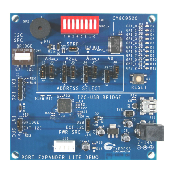
Page 6: Step 2. Hardware Configuration
8. Wait until program installation finishes. Click the Finish button. Installation is complete. The Program icon is located under Start Menu >> Programs >> Cypress MicroSystems… by default. The remainder of this quick start guide outlines creating an example project, configuring the hardware, setting up and generating a project in the Expander Configuration software, and downloading the project to the target device. - Page 7 2. Select power source. The demonstration board can be powered by one of three independent power sources: an external 7-14V DC supply via a linear regulator, a regulated 3.3-5V supply by connection to J11, or 5V power supply from a PC via the USB cable. This example will use the third option, which requires J14 to be set in the 2-3 position, as shown in the photo below.
-
Page 8: Step 3. Software Configuration
1. Open an existing or create a new Expander Configuration software project (the software was installed in Step 1). The software program icon is located under Start Menu >> Programs >> Cypress MicroSystems. To open an existing project, click the menu item File >> Open Project. In the Open Project dialog box select your project and click the Open button. - Page 9 Or, to create a new project, click the menu item File >> New Project. In the New Project dialog box specify project location, part type and project name. Click the OK button. I2C Port Expander Lite Demo Kit Getting Started Guide...
- Page 10 You will then see a workspace similar to the image below. The I2C Port Expander window shows all internal resources of the target device. The I2C EEPROM window shows an image of the EEPROM data. 2. Set the Port Expander address. To do this, click the I2C Port Expander tab. In the Address Assignment Section (upper-right corner), specify address length and expander address.
- Page 11 3. Configure Port Expander internal resources. To do this we must generate two output signals on pins P1[0] and P1[1]. The signal frequencies are 1 Hz and 4 Hz, respectively. For this purpose we utilize three PWMs, and two pins and the clock divider resources. Also, the EEPROM must contain the "Hello world!"...
- Page 12 e. Click on the PWM2 resource and define its properties as follows: Clock: cv_PrevPWM IntLogic: Falling_Edge Period: PulseWidth: Select P1[0] and P1[1] pins by holding the [Shift] key down and clicking the corresponding pin images. Some editing can be done at this time in the Properties window. Configure the selected pin properties as follows: Data: High...
- Page 13 h. Turn off the other LEDs Select all the unused P1[x] and P2[x] pins and set them to: Data: Direction: Output DriveMode: Strong Interrupt: Disable Inversion: Not Checked (Disable) PinMode: GPIO Enable the EEPROM Click on the EEPROM block and set the options using the Properties Window: EnableEEPROM: Checked ReadOnly:...
- Page 14 4. Define EEPROM image addresses/text string. Click the I2C EEPROM tab. You can type characters in the far right column or HEX digits in the individual HEX columns. See the following: 5. Set configuration script options. To set the options, click the menu item Tools >> Script Generator Options.
- Page 15 6. Generate configuration script. To generate the configuration script, click the menu item Tools >> Generate Configuration Script File. Once generation is complete, the script is located in the project folder and has the same name as the project and “iic” extension, for example, FirstExpanderProject.iic. 7.
- Page 16 Step 4b Download Configuration using the I2C-USB Bridge GUI If this software is not installed, you will need to install it in order to download the script and program the target device. For details, refer to the I2C-USB Bridge Quick Start Guide. Following is a simplified version of the instructions: 1.
- Page 17 The red and green LEDs on the bridge portion of the board will light up. Green LED D15 Red LED 3. Click the button and make sure that the corresponding device (CY8C9520) with address 0x2B is connected. 4. Click the button.
- Page 18 Step 5. Your first project is finished. If everything was done correctly, there will be 1 Hz and 4 Hz frequencies on pins P1[0] and P1[1] and the corresponding LEDs should be blinking. Also, the EEPROM will contain the "Hello World!" string. This can be verified using the I2C-USB Bridge GUI by sending the following command strings.
- Page 19 I2C Port Expander Lite Demo Kit Getting Started Guide...
Need help?
Do you have a question about the CY3242-IOXlite and is the answer not in the manual?
Questions and answers