Advertisement
Quick Links
Suprex
®
RF
SPX-5631 & SPX-5641
Wireless Reader-Extender
Product Manual
SPX-5631
2.4 GHz
EXP-2000
SPX-5631_SPX-5641_MAN_181129
Cypress Integration Solutions
35 Years of Access Control Ingenuity
CypressIntegration.com
© 2018 Cypress Computer Systems
1778 Imlay City Road, Lapeer, MI 48446
800-807-2977
Advertisement

Related Manuals for Cypress Suprex SPX-5631


Summary of Contents for Cypress Suprex SPX-5631
- Page 1 Suprex ® SPX-5631 & SPX-5641 Wireless Reader-Extender Product Manual SPX-5631 2.4 GHz EXP-2000 SPX-5631_SPX-5641_MAN_181129 Cypress Integration Solutions 35 Years of Access Control Ingenuity CypressIntegration.com © 2018 Cypress Computer Systems 1778 Imlay City Road, Lapeer, MI 48446 800-807-2977...
- Page 2 Cypress Suprex® RF Series - SPX-5631 & SPX-5641 Overview The Suprex® RF SPX-5631 and SPX-5641 series makes it possible to install card readers far from the access control panel, by providing a point-to-point wireless link between most manufacturers’ controllers and the door or gate readers.
- Page 3 Table of Contents Topic Page Overview and Specifications Physical Dimensions and Mounting Hole Locations Central and Remote Pin Layout Setup and Pre-Installation Indicators and Operating Modes Common Configuration and Run Mode Settings DIP Switch Map Using Remote Digital Relay Inputs Quick Reference for Typical Connections Repeater Installation Troubleshooting...
- Page 4 Cypress Suprex® RF Series - Physical Dimensions and Mounting Hole Locations 3.065" 2.770" ø 0.120 X 4 9.25" SPX-5631 / Thickness: SPX-5641 / 2.25" RPT-5651 4.0625" 7.0" 3.155" 2.890" ø 0.120 X 4 EXP Enclosure EXP-2000 4.125" All dimensions are listed in inches.
- Page 5 Cypress Suprex® RF Series - Central and Remote Pin Layout SPX-5631 / SPX-5641 Central Unit 8-16VDC Input Ground Relay 4 N.O. Relay 4 COM Relay 4 N.C. Relay 3 N.O. EXP (+) Relay 3 COM EXP (-) Relay 3 N.C.
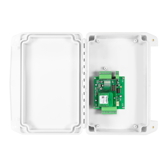
- Page 6 Cypress Suprex® RF Series - Setup and Pre-installation Unpacking: Remove covers from units and check interior for any shipping damage. Remove any packing material if present. Inventory any included parts (depending on model) such as antennas, coaxial cables etc. Bench Testing: Before installing the units in the field they should be assembled and tested at a convenient benchtop location.
- Page 7 Cypress Suprex® RF Series - Indicators and Operating Modes LED DIAGNOSTIC INDICATOR The LED Diagnostic indicator provides information on the operational status of the unit. If the units are not communicating, viewing the diagnostic indicator LEDs may help to determine the nature of the problem.
- Page 8 Cypress Suprex® RF Series - Common Configuration and Run Mode Settings Configuration Mode settings Standard Wiegand interface is the default setting. To use with non-Wiegand interface: a) Power off both Suprex units. b) Turn on DIP switch 1 on both units.
-
Page 9: Run Mode
Cypress Suprex® RF Series - SPX-5631 / SPX-5641 DIP Switch Map Run Mode Configuration Mode Test Mode 1 2 3 4 5 6 7 8 1 2 3 4 5 6 7 8 1 2 3 4 5 6 7 8 Configuration Mode Select - ON = Configuration Mode - OFF = Run Mode... - Page 10 Cypress Suprex® RF Series - Using the Remote Digital Relay Inputs This section applies only to the Remote unit, as the Central unit has only digital relay inputs. DIP switch 2 controls whether the Remote unit uses the analog relay inputs or the digital relay inputs. By default, DIP switch 2 is off and the Remote unit is set to use the analog relay inputs.
-
Page 11: Dc Power Supply
Cypress Suprex® RF Series - Quick Reference For Typical Connections DC Power SPX-5631 / SPX-5641 Central Supply Power Ground +8 to +16 VDC Relay 4 N.O. Ground Relay 4 Com Relay 4 N.C. Access exp(+) Relay 3 N.O. Control exp(-) - Page 12 Cypress Suprex® RF Series - Repeater Installation Remote Obstacle Central Repeater For environments with obstacles that do not allow the Central and Remote units to have line of sight, or which need greater distances covered, a Repeater can be used. The diagram above shows the Repeater being used to get around an environmental obstacle.
- Page 13 Cypress Suprex® RF Series - Troubleshooting No Communication When the Central and/or Remote unit is not communicating with its partner unit, the status LED will flash green/red. To troubleshoot communication issues, check the following: • Power: • Both units must be powered.
- Page 14 Cypress Suprex® RF Series - Accessory I/O - Overview The Cypress SPX-5631 or SPX-5641 provides additional data channels to support access control hardware such as door strikes, tamper alarms, request to exit status, etc. These signals are sent to and from the Central and Remote units without the need to run additional wiring.
- Page 15 Cypress Suprex® RF Series - Accessory I/O - Central Relay Inputs To activate the relay on the Remote unit, connect as shown below. These connections can be used to allow the Remote relay to operate a DOOR STRIKE, GATE, or other locking hardware. The diagram below shows two methods of triggering the relays.
- Page 16 Cypress Suprex® RF Series - Accessory I/O - Relay 1 & 2 I/O Relay 1 I/O Diagram This diagram illustrates how the state of the Relay +8 to +16 VDC +8 to +16 VDC Relay 4 N.O. Relay 4 N.O.
- Page 17 Cypress Suprex® RF Series - Accessory I/O - Remote Relay Inputs To activate the relay on the Central unit, connect as shown below. These connections can be used to operate a REX switch or other signals that need to go to the access panel.
- Page 18 Cypress Suprex® RF Series - Accessory I/O - Relay 3 & 4 I/O Relay 3 I/O Diagram This diagram shows how +8 to +16 VDC +8 to +16 VDC Relay 4 N.O. Relay 4 N.O. Ground Ground the state of the the Relay 3...
- Page 19 Cypress Suprex® RF Series - Accessory I/O - LED I/O For access control panels with a LED Output signal, the SPX-5631 / SPX-5641 is able to transmit this signal to the reader with the LED Input and LED Output pins. The LED In pin is a digital input and the LED Out pin is a digital output.
- Page 20 Cypress Suprex® RF Series - Accessory I/O - AUX I/O The SPX-5631 / SPX-5641 has an auxiliary I/O signal going from the reader side to the panel side. The SPX-5631 / SPX-5641 is able to transmit this signal to the panel with the AUX Input and AUX Output pins. The AUX In pin is a digital input and the AUX Out pin is a digital output.
-
Page 21: Normally Closed Contact
Application Note on using Supervised contacts with the Suprex® RF Series The following applies to these products: SPX-5631 and SPX-5641. This application note describes the connections necessary to convey supervised contact status over a Suprex®. The configurations described in this application note should apply to most panels which utilize supervised contacts. When connected as described, the Suprex®... - Page 22 • EXP status LED is flashing green: EXP unit is properly communicating with the Suprex®. • The EXP-2000 Central and Remote pair will be functionally similar to the standard Cypress SPX-1300 Suprex® system. For more details, see the EXP-2000 manual.
- Page 23 Cypress Suprex® RF Series - Suprex Central and EXP Central Wiring Diagram +8 to +16 VDC Relay 4 N.O. Ground Suprex DC Power Relay 4 Com Supply Central Relay 4 N.C. exp(+) Relay 3 N.O. Power exp(-) Relay 3 Com...
- Page 24 Cypress Suprex® RF Series - Suprex Remote and EXP Remote Wiring Diagram +8 to +16 VDC Relay 2 N.O. Ground DC Power Suprex Relay 2 Com Supply Relay 2 N.C. Remote exp(+) Relay 1 N.O. exp(-) Power Relay 1 Com...
- Page 25 Cypress Suprex® RF Series - Radio Configuration Channel Network Meter Display All Off 1 2 3 4 5 6 7 Link Quality 1778 1 2 3 4 5 6 7 8 9 10 1779 Energy Channel 1780 Antenna Select 1781...
-
Page 26: Meter Display
Cypress Suprex® RF Series - Radio Configuration (Continued) Meter Display Signal Strength Meter DIP switch 8 controls what the 5 LEDs on the daughter board display. The 5 LEDs can display Signal Strength or Ambient RF Energy. Refer to the diagram above (on page 25) in order set the unit to display Signal Strength or Ambient RF Energy.
Need help?
Do you have a question about the Suprex SPX-5631 and is the answer not in the manual?
Questions and answers