Advertisement
Quick Links
Download this manual
See also:
Operating Manual
Advertisement

Related Manuals for Cypress Suprex Ethernet SPX-7200 Series


Summary of Contents for Cypress Suprex Ethernet SPX-7200 Series
- Page 1 Suprex Ethernet ® SPX-7200 Ethernet Reader-Extender Product Manual SPX-7200_MAN_181206 Cypress Integration Solutions 35 Years of Access Control Ingenuity CypressIntegration.com © 2018 Cypress Computer Systems 1778 Imlay City Road, Lapeer, MI 48446 800-807-2977...
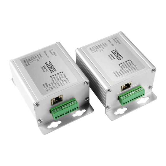
- Page 2 Cypress Suprex® Ethernet Series - SPX-7200 Overview The Suprex Ethernet SPX-7200 series makes it possible to install card readers far from the access control panel, by providing a network link between the door or gate readers, and most manufacturers’ panels. The Suprex includes both a Remote (door/gate) unit and a Central (Controller) unit.
- Page 3 Table of Contents Topic Page Overview and Specifications Physical Dimensions and Mounting Hole Locations Central and Remote Pin Layout Setup and Pre-Installation Indicators and Operating Modes Common Configuration and Run Mode Settings DIP Switch Map Quick Reference for Typical Connections SPX-7200 Network Settings Changing Network Adaptor Settings in Windows 12 - 14...
- Page 4 Cypress Suprex® Ethernet Series - Physical Dimensions and Mounting Hole Locations 3.065" 2.770" ø 0.120 X 4 SPX-7200 Enclosure SPX-7200 4.0625" 3.155" 2.890" ø 0.120 X 4 EXP-2000 Enclosure EXP-2000 4.125" All dimensions are listed in inches.
- Page 5 Cypress Suprex® Ethernet Series - Central and Remote Pin Layout SPX-7200 Central 8-16VDC Input Ground Relay 4 N.O. Relay 4 COM Relay 4 N.C. Relay 3 N.O. EXP(+) Relay 3 COM EXP(-) Relay 3 N.C. +5VDC Output Ground Prog Res 2...
- Page 6 Cypress Suprex® Ethernet Series - Setup and Pre-installation Unpacking: Remove Central and Remote units from from the packaging material and check interior for any shipping damage. Inventory any included parts (depending on model) such as terminal connectors. Bench Testing: Before installing the units in the field they should be assembled and tested at a convenient bench top location. This will make it easier to verify / change settings and check operation when both units are visible at the same time.
- Page 7 Cypress Suprex® Ethernet Series - Indicators and Operating Modes LED DIAGNOSTIC INDICATOR The LED Diagnostic indicator provides information on the operational status of the unit. If the units are not communicating, viewing the diagnostic indicator LEDs may help to determine the nature of the problem (see Troubleshooting, pg.
- Page 8 Cypress Suprex® Ethernet Series - Common Configuration and Run Mode Settings Configuration Mode settings Standard Wiegand interface is the default setting. To use with non-Wiegand interface: a) Power off both Suprex units. b) Turn on DIP switch 1 on both units.
- Page 9 Cypress Suprex® Ethernet Series - SPX-7200 DIP Switch Map Run Mode Configuration Mode Test Mode 1 2 3 4 5 6 7 8 1 2 3 4 5 6 7 8 1 2 3 4 5 6 7 8 Configuration Mode Select - ON = Configuration Mode - OFF = Run Mode...
- Page 10 Cypress Suprex® Ethernet Series - Quick Reference For Typical Connections DC Power SPX-7200 Central Supply Power Ground +8 to +16 VDC Relay 4 N.O. Ground Relay 4 Com Relay 4 N.C. Access exp(+) Relay 3 N.O. Control exp(-) Relay 3 Com...
- Page 11 Suprex® Ethernet Series - SPX-7200 Network Settings Overview: The following sections cover how to connect a computer to an SPX-7200 Central and/or Remote and change the network settings of the device. These sections include: • SPX-7200 Network Settings • SPX-7200 Enabling Telnet Client •...
- Page 12 Suprex® Ethernet Series - Changing Network Adaptor Settings in Windows This section covers how to change the Network Adaptor settings on Windows 7, Windows 8, and Windows 10. Regardless of the method used, it is necessary to change the network adaptor settings when connecting SPX-7200 Central or Remote units to the computer.
- Page 13 Suprex® Ethernet Series - Changing Network Adaptor Settings in Windows (cont.) Step 3 Disable the Wireless Network Connection, if one is present. Right-click the Wireless Network Connection box and select disable. Step 4 Right-click Local Area Connection and select Properties.
- Page 14 Suprex® Ethernet Series - Changing Network Adaptor Settings in Windows (cont.) Step 5 Click Internet Protocol Version 4 (TCP/IPv4) in the list. Click Properties, below the list. Step 6 Select Use the following IP address: Step 7 If the Central or Remote unit has not had its network settings changed, use the IP address and Subnet Mask in Step 8. Otherwise use an IP address and Subnet Mask that is compatible with how the Central or Remote unit is configured.
- Page 15 Suprex® Ethernet Series - SPX-7200 Network Settings via Web Browser Connecting to the SPX-7200 via a Web Browser: Step 1 Connect the SPX-7200 Central or Remote unit to a computer with a network cable. Make sure the computer’s network adaptor settings are set to be compatible with the SPX-7200. If necessary, follow the steps in the Changing Network Adaptor Settings in Windows section (see pgs.
- Page 16 Suprex® Ethernet Series - SPX-7200 Network Settings via Web Browser Step 4 A menu titled Device Status will appear. Click Network on the left. Step 5 Enter the desired IP address of the unit. Enter other information if necessary. Scroll to the bottom of the page. Click OK. “Done!”...
- Page 17 Suprex® Ethernet Series - SPX-7200 Network Settings via Web Browser (cont.) Step 6 On the left, click Connections. Locate Remote Host under Endpoint Configuration. Enter the IP address of the partner unit. If connected to the Central unit, enter the Remote unit’s IP address. If connected to the Remote unit, enter the Central unit’s IP address.
- Page 18 Suprex® Ethernet Series - SPX-7200 Network Settings via Telnet Connecting to the SPX-7200 via Telnet: Step 1 Connect the SPX-7200 Central or Remote unit to a computer with a network cable. Make sure the computer’s network adaptor settings are set to be compatible with the SPX-7200. If necessary, follow the steps in the Changing Network Adaptor Settings in Windows section (see pgs.
- Page 19 Suprex® Ethernet Series - SPX-7200 Network Settings via Telnet (cont.) Step 5 Press enter again. The Change Setup menu will appear. To change the unit’s IP address, press 0 to enter the Server menu. Step 6 The first prompt is the IP address. If a new IP address is required, enter the IP new IP address and press enter. If a new IP address is not required, simply press enter for each section of the IP address and the current IP address will auto fill in each section.
- Page 20 Suprex® Ethernet Series - SPX-7200 Network Settings via Telnet (cont.) Step 7 Press 1 to enter the Channel 1 menu. Press the enter key 8 times to get to Remote IP Address. Enter the IP address of the partner unit. If connected to the Central unit, enter the IP address of the Remote unit. If connected to the Remote unit, enter the IP address of the Central unit.
- Page 21 Suprex® Ethernet Series - Enabling Telnet Client Enabling Telnet: If the error message shown in the image below appears when attempting to connect to the SPX-7200 Central or Remote unit, the Telnet Client is not enabled. This section covers how to enable the Telnet Client. Step 1 Get to Control Panel.
- Page 22 Suprex® Ethernet Series - Enabling Telnet Client (cont.) Step 2 Click on Programs and Features in the Control Panel window. Step 3 Click “Turn Windows Features on or off” on the left side of the window.
- Page 23 Suprex® Ethernet Series - Enabling Telnet Client (cont.) Step 4 A new window, titled “Windows Features”, will appear. Wait for the list to be populated, then scroll down to an item called “Telnet Client”. Check the check box next to Telnet Client. Step 5 Click the OK button at the bottom of the window.
- Page 24 Cypress Suprex® Ethernet Series - Troubleshooting No Communication When the Central and/or Remote unit is not communicating with its partner, the status LED will flash green/red. To troubleshoot communication issues, check the following: • Power: • Both units must be powered.
-
Page 25: I/O Overview
Cypress Suprex® Ethernet Series - Accessory I/O - Overview The Cypress SPX-7200 provides additional data channels to support access control hardware such as door strikes, tamper alarms, request to exit status, etc. These signals are sent to and from the Central and Remote units without the need to run additional wiring. -
Page 26: Central Relay Inputs
Cypress Suprex® Ethernet Series - Accessory I/O - Central Relay Inputs To activate the relay on the Remote unit, connect as shown below. These connections can be used to allow the Remote relay to operate a DOOR STRIKE, GATE, or other locking hardware. The diagram below shows two methods of triggering the relays. - Page 27 Cypress Suprex® Ethernet Series - Accessory I/O - Relay 1 & 2 I/O Relay 1 I/O Diagram This diagram shows how +8 to +16 VDC +8 to +16 VDC the state of the the Relay 1 Relay 4 N.O. Relay 4 N.O.
-
Page 28: Remote Relay Inputs
Cypress Suprex® Etherent Series - Accessory I/O - Remote Relay Inputs To activate the relay on the Central unit, connect as shown below. These connections can be used to operate a REX switch or other signals that need to go to the access panel. - Page 29 Cypress Suprex® Ethernet Series - Accessory I/O - Relay 3 & 4 I/O Relay 3 I/O Diagram This diagram shows how +8 to +16 VDC +8 to +16 VDC Relay 4 N.O. Relay 4 N.O. Ground Ground the state of the the Relay 3...
- Page 30 Cypress Suprex® Ethernet Series - Accessory I/O - LED I/O For access control panels with a LED Output signal, the SPX-7200 is able to transmit this signal to the reader with the LED Input and LED Output pins. The LED In pin is a digital input and the LED Out pin is a digital output. The LED In pin has two states, 5V (high or normal) and 0V (low or active).
- Page 31 Cypress Suprex® Ethernet Series - Accessory I/O - AUX I/O The SPX-7200 has an auxiliary I/O signal going from the reader side to the panel side. The SPX-7200 is able to transmit this signal to the panel with the AUX Input and AUX Output pins. The AUX In pin is a digital input and the AUX Out pin is a digital output.
-
Page 32: Remote Digital Relay Inputs
Cypress Suprex® Ethernet Series - Accessory I/O - Remote Digital Relay Inputs Note: This section applies only to the Remote unit, which can use analog or digital relay inputs, since the Central unit has only digital relay inputs. DIP switch 2 controls whether the Remote unit uses analog or digital relay inputs. By default, DIP switch 2 is off and the Remote unit is set to use analog relay inputs. -
Page 33: Application Note On Using Supervised Contacts
Application Note on using Supervised contacts with the Suprex® Ethernet Series The following applies to these products: SPX-7200. This application note describes the connections necessary to convey supervised contact status over a Suprex®. The configurations described in this application note should apply to most panels which utilize supervised contacts. When connected as described, the Suprex®... -
Page 34: Using Exp-2000 Expansion Modules
• EXP status LED is flashing green: EXP unit is properly communicating with the Suprex. • The EXP-2000 Central and Remote pair will be functionally similar to the standard Cypress SPX-1300 Suprex system. For more details, see the EXP-2000 manual. - Page 35 Cypress Suprex® Addendum - Suprex Central and EXP Central Wiring Diagram +8 to +16 VDC Relay 4 N.O. Ground Suprex DC Power Relay 4 Com Supply Central Relay 4 N.C. exp(+) Relay 3 N.O. exp(-) Power Relay 3 Com Ground +5V Out Relay 3 N.C.
- Page 36 Cypress Suprex® Addendum - Suprex Remote and EXP Remote Wiring Diagram +8 to +16 VDC Relay 2 N.O. Ground DC Power Suprex Relay 2 Com Supply Relay 2 N.C. Remote exp(+) Relay 1 N.O. Power exp(-) Relay 1 Com Ground +5V Out Relay 1 N.C.
Need help?
Do you have a question about the Suprex Ethernet SPX-7200 Series and is the answer not in the manual?
Questions and answers