Advertisement
Quick Links
Advertisement

Related Manuals for Cypress SPX-1300


Summary of Contents for Cypress SPX-1300
- Page 1 SPX-1300 Operations Manual Cypress Suprex® Reader Extender SPX-1300_MAN_030513...
- Page 2 Electrical and Mechanical Specifications Physical SPX-1300 Aluminum Enclosure 3.5" x 2.75" x .75" SPX-1300 Aluminum Enclosure 3.5" x 2.75" x .75" Storage(-55˚C to + 150˚C) Storage(-55˚C to + 150˚C) Temp Operating(-40˚C to +80˚C) Operating(-40˚C to +80˚C) Humidity 95% (non-condensing) 95% (non-condensing)
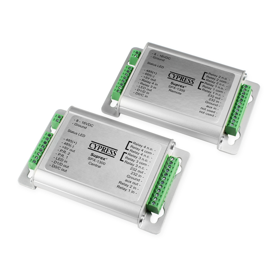
- Page 3 External connections and DIP Switch Settings 2-8 to 16 VDC In 1-Ground 12-RLY4 N.O. 11-RLY4 Com 10-RLY4 N.C. Diagnostic LED 9-RLY3 N.O. 8-RLY3 Com 8-485(+) 7-RLY3 N.C. 7-485(-) 6-RS232 Out Central Unit 6-+5 VDC Out 5-RS232 In 5-Prog Res 2 4-Ground 4-Prog Res 1 3-Aux Out...
-
Page 4: Electrical And Environmental Specifications
Supply Voltage Temperature/Voltage de-rating curve The SPX-1300 units should be operated with a filtered 12 Volt nominal DC supply. However, any voltage between 8 and 16 volts can be utilized by following the temperature /voltage derating curve. Voltage should not exceed 16 VDC. - Page 5 Troubleshooting - Diagnostic Indicators When the Suprex units are operating correctly and have a valid communication channel between the Remote and Central units the Diagnostic indicators on each unit will flash green rapidly (2-3 flashed per second). If the units are not communicating, viewing the diagnostic indicator LED’s may help to determine nature of the problem.
-
Page 6: Power Supply
Suprex Operation and Initial Setup Actual connections will differ based on the type of format, features utilized, and equipment interface. The following diagrams are an example of a typical installation using the Suprex 1300 and a Wiegand format Reader and Access Control Panel. 1. - Page 7 3. Connect the Reader to the Remote unit. 2 different standard applications are shown as examples below. Note: The LED and Door Strike operation of the SPX-1300 differs from previous versions. The connection and operation is covered in the next 2 pages.
- Page 8 Suprex Operation and Initial Setup Central Side Basic Panel Connections 4. Connect the Central unit to the Access control panel. Power can be supplied by either the Access Control Panel or an External Power supply. A ground connection must be provided to the Suprex unit in either case. 2-8 to 16 VDC In 1-Ground 12-RLY4 N.O.
- Page 9 Suprex Operation and Initial Setup Central Side Basic Panel Connections 5. To activate the relay on the Remote unit connect as shown below. These connections can be used to allow the Remote relay to operate a DOOR STRIKE, GATE, or other locking hardware. Refer to following pages in this document for details of each I/O operation and connection.
- Page 10 Suprex Operation and Initial Setup I/O Controls 6. The Cypress SPX-1300 provides additional data channels to support access control hardware such as door strikes, tamper alarms, request to exit status, etc. These signals are sent to and from the Remote and Central units without the need to run additional wiring.
- Page 11 Suprex Operation and Initial Setup I/O Controls 2-8 to 16 VDC In 1-Ground 12-RLY4 N.O. 11-RLY4 Com 10-RLY4 N.C. 9-RLY3 N.O. 8-RLY3 Com 8-485(+) 7-RLY3 N.C. 7-485(-) 6-RS232 Out Central Unit 6-+5 VDC Out 5-RS232 In 5-Prog Res 2 4-Ground 4-Prog Res 1 3-Aux Out Input...
- Page 12 Suprex Operation and Initial Setup I/O Controls 2-8 to 16 VDC In 1-Ground 12-RLY4 N.O. 11-RLY4 Com 10-RLY4 N.C. 9-RLY3 N.O. 8-RLY3 Com 8-485(+) 7-RLY3 N.C. 7-485(-) 6-RS232 Out Central Unit 6-+5 VDC Out 5-RS232 In 5-Prog Res 2 4-Ground Input 4-Prog Res 1 3-Aux Out...
- Page 13 Suprex Operation and Initial Setup I/O Controls 2-8 to 16 VDC In 1-Ground 12-RLY4 N.O. 11-RLY4 Com 10-RLY4 N.C. 9-RLY3 N.O. 8-RLY3 Com 8-485(+) 7-RLY3 N.C. 7-485(-) 6-RS232 Out Central Unit 6-+5 VDC Out 5-RS232 In 5-Prog Res 2 4-Ground Input 4-Prog Res 1 3-Aux Out...
- Page 14 Suprex Operation and Initial Setup I/O Controls 2-8 to 16 VDC In 1-Ground 12-RLY4 N.O. 11-RLY4 Com Output 10-RLY4 N.C. 9-RLY3 N.O. 8-RLY3 Com 8-485(+) 7-RLY3 N.C. 7-485(-) 6-RS232 Out Central Unit 6-+5 VDC Out 5-RS232 In 5-Prog Res 2 4-Ground 4-Prog Res 1 3-Aux Out...
- Page 15 Suprex Operation and Initial Setup I/O Controls Output 2-8 to 16 VDC In 1-Ground 12-RLY4 N.O. 11-RLY4 Com 10-RLY4 N.C. 9-RLY3 N.O. 8-RLY3 Com 8-485(+) 7-RLY3 N.C. 7-485(-) 6-RS232 Out Central Unit 6-+5 VDC Out 5-RS232 In 5-Prog Res 2 4-Ground 4-Prog Res 1 3-Aux Out...
- Page 16 Suprex Operation and Initial Setup I/O Controls 2-8 to 16 VDC In 1-Ground 12-RLY4 N.O. 11-RLY4 Com 10-RLY4 N.C. 9-RLY3 N.O. 8-RLY3 Com 8-485(+) 7-RLY3 N.C. 7-485(-) 6-RS232 Out Central Unit 6-+5 VDC Out 5-RS232 In Output 5-Prog Res 2 4-Ground 4-Prog Res 1 3-Aux Out...
- Page 17 SPX-XXXX Application Note Using Supervised Contacts with the SPX-series Extenders Applies to the following products: SPX-1300 and EXP series products. This application note describes the connections necessary to convey supervised contact status over a Suprex® communication link. The configurations described in this app note should apply to most panels that utilize supervised contacts.
Need help?
Do you have a question about the SPX-1300 and is the answer not in the manual?
Questions and answers