
Related Manuals for Cypress SPX-1200


Summary of Contents for Cypress SPX-1200
- Page 1 SPX-1200 Supervised Reader Extender Wiring Diagram and Operators Manual MAN-FA-SPX-1200 V1.04 ©2006 Cypress Computer Systems,Inc. • www.cypressworld.com Page 1...
-
Page 2: Table Of Contents
Supervised contacts and programming resistors Page 25,26 Part numbers for different versions: SPX-1200: RS-485 Twisted pair, wired version. FCC Part 15 COMPLIANCE This device complies with part 15 of the FCC Rules. Operation is subject to the following two conditions:... - Page 3 Rly Com Rly N.O. RS-232RX Aux Output 1 RS-232 TX Line - Line + Data0/Strobe/F2F Data 1/Data LED IN Aux Output 2 Aux Input 3 5Vdc +8 - 24VDC Suprex 1200 Central Unit ©2006 Cypress Computer Systems,Inc. • www.cypressworld.com Page 3...
- Page 4 Strobed Rising (Mag-Tek) Strobed Falling Edge Strobed Falling Edge 6 x x 6 x x Reserved Reserved 7 x x x 7 x x x CENTRAL Dip Switch Settings REMOTE Dip Switch Settings ©2006 Cypress Computer Systems,Inc. • www.cypressworld.com Page 4...
- Page 5 Tamper, Alarm, and Door contacts over the same communication link. An SPX-1200 system consists of a pair of units. A Central unit connects to the Access Control Panel and a Remote unit connects to the Badge reader and door/ gate hardware. The reader data and status signals are sent over a single pair of wires up to 10,000 feet.
- Page 6 Strike / LED signals are operating in the expected manner. 7. Install the units in their final locations. See the following pages for details on connection and configuration of the SPX-1200. ©2006 Cypress Computer Systems,Inc. • www.cypressworld.com...
- Page 7 LED will flash green on and off about twice per second. DIP Switch Settings: The Cypress Suprex supports multiple reader data formats. Each data format can be set with the dipswitch. The dip switch format will be read each time the unit powers up.
-
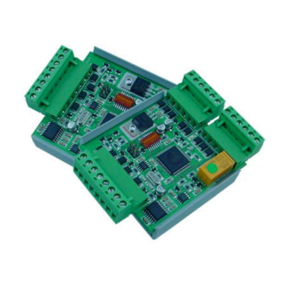
Page 8: Identification Of Major Components
The Cypress Suprex System consists of a Central and a Remote unit. Each Suprex board has connections for a card reader, Relay and I/O, and Power and communications. The Central board has connections for the control panel’s reader port, I/O points, and Power and Communications. - Page 9 Aux. Digital I/O #3 Input Alarm Relay N.C.. Alarm Relay Com Alarm Relay N.O. Aux. Digital I/O #1 Output RS-485 Line - RS-485 Line + +5 VDC Ground +8 - 24 VDC ©2006 Cypress Computer Systems,Inc. • www.cypressworld.com Page 9...
- Page 10 Alarm Relay Com Alarm Relay N.O. Aux. Digital I/O #3 Output RS-485 Line - RS-485 Line + Data 1 / Data Data 0 / Clock / F2F +5 VDC Ground +8 - 24 VDC ©2006 Cypress Computer Systems,Inc. • www.cypressworld.com Page 10...
- Page 11 The power supply can be located at either the Central or Remote unit. However, only one power supply should be used for this configuration. Power Supply Line - +8 to 24 VDC Line + +V Gnd ©2006 Cypress Computer Systems,Inc. • www.cypressworld.com Page 11...
- Page 12 Remote unit. It requires 2 wires to connect the two units together. The power supplies are located at both the Central and Remote units. Line - Line + Power Supply +8 to 24 VDC Power Supply +8 to 24 VDC ©2006 Cypress Computer Systems,Inc. • www.cypressworld.com Page 12...
- Page 13 The +8 to 24 and 5 Volt supplies should NEVER be connected or used at the same time. Illustration shows both units with 5 volt power supply. Line - Line + Power Supply 5 VDC Power Supply 5 VDC ©2006 Cypress Computer Systems,Inc. • www.cypressworld.com Page 13...
-
Page 14: Communication Connections
Do not proceed further if this is not the case. Refer to the troubleshooting guide to correct any problems. Power Supply Line - +8 to 24 VDC Line + +V Gnd Communication Active, Green Green Power flashing approx 2 indicator times per second. ©2006 Cypress Computer Systems,Inc. • www.cypressworld.com Page 14... -
Page 15: Reader Data Connections
The diagrams below show data connections for the reader signals. Power and communication connections are still present, but have been removed from the diagram for clarity. The SPX-1200 has eliminated the need for “Pullup” resistors in most installations. Dipswitch #4 controls whether the internal pullup resistors are turned on or not. - Page 16 Detailed Reader Port Connections- Central unit Power supply connections are not shown for clarity. Panel/Port Signals Ground Data 0 / Clock / F2F Data 1 / Data ©2006 Cypress Computer Systems,Inc. • www.cypressworld.com Page 16...
- Page 17 Reader Data 1 / Data Data 0 / Clock / F2F +5 VDC Ground Reader Interface +12 Vdc Reader Data 1 / Data Data 0 / Clock / F2F Ground +12 VDC ©2006 Cypress Computer Systems,Inc. • www.cypressworld.com Page 17...
-
Page 18: Door Strike Relay
Door Strike on Remote Unit. LED signal from panel activates LED and Door Strike on Remote Unit. Central Unit Reader interface Door Strike Contacts N.C. Contact Common N.O.. Contact Reader LED Remote Unit ©2006 Cypress Computer Systems,Inc. • www.cypressworld.com Page 18... - Page 19 Auxiliary Digital I/O Input triggers Strike Relay Central Unit Strike Relay Follows Aux input on Central N.C. Contact Common N.O.. Contact Auxiliary Digital output follows Aux. input on Central Reader LED Remote Unit ©2006 Cypress Computer Systems,Inc. • www.cypressworld.com Page 19...
- Page 20 Follow Digital Input #1 From Remote Open Collector (Aux output #1) Follows Alarm Condition Alarm and Digital Input signals Central Unit from Remote Unit. Aux Input #2 Aux Input #1 Remote Unit ©2006 Cypress Computer Systems,Inc. • www.cypressworld.com Page 20...
-
Page 21: Auxiliary Inputs And Outputs
The Alarm supervision relay will close when both the Central and Remote units are powered up and communicating. For applications that require a dry relay contact for Auxiliary I/O functions, an adapter board is available. Cypress Part Number SPX-RLY1 Auxiliary I/O uses 0 to +5 VOLT signals only ©2006 Cypress Computer Systems,Inc. • www.cypressworld.com Page 21... - Page 22 Aux Output 3 Aux Input 2 Aux Input 1 Suprex 1200 Remote Unit Rly N.C. Alarm Output Rly Com Rly N.O. Aux Output 1 Aux Output 2 Aux Input 3 Suprex 1200 Central Unit ©2006 Cypress Computer Systems,Inc. • www.cypressworld.com Page 22...
- Page 23 Here are several examples of driving the Suprex-1200 series digital inputs using standard field wiring practices. Activating a digital input with relay or switch contacts. Ground Digital Input Activating a digital input with open collector output device. Ground Open Collector Output Digital Input ©2006 Cypress Computer Systems,Inc. • www.cypressworld.com Page 23...
- Page 24 Opto 22 or Crydom products using a logic level input. See relay manufacturers documentation for electrical and connection requirements. + 5 Volts from Suprex Solid State Relay Contacts Digital Output ©2006 Cypress Computer Systems,Inc. • www.cypressworld.com Page 24...
Need help?
Do you have a question about the SPX-1200 and is the answer not in the manual?
Questions and answers