Table of Contents
Advertisement
Quick Links
USER'S GUIDE
EE210 - Humidity and Temperature Transmitter for
demanding Climate Control Applications
GENERAL
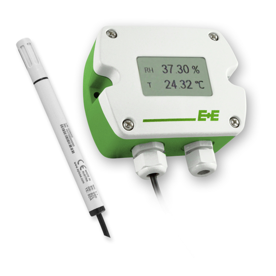
The EE210 transmitter, available for wall or duct mounting, is designed for the highly accurate measurement of humidity and tempera-
ture in demanding climate control applications. The EE210 incorporates the E+E humidity and temperature sensor HCT01.
For use in special applications do not hesitate to contact E+E Elektronik or a local distributor.
CAUTION
•
For accurate measurement it is essential that the temperature of the sensing probe and mainly of the sensing head is same as
the temperature of the air to measure. Avoid mounting the transmitter in a way which creates temperature gradients along the
probe.
•
The transmitter and mainly the sensing head shall not be exposed to extreme mechanical stress.
•
The transmitter must be operated with the filter cap on at all times.Do not touch the sensors inside the sensing head.
•
While replacing the filter cap (because of pollution for instance) against an original spare one please take very good care to
not touch the sensors.
CONNECTION DIAGRAM
EE210-HT6*
ONLy FOR REMOTE PROBE!
EE210-HT3
EE210-HTx3
ONLy FOR REMOTE PROBE!
*Important:
In the case of EE210-HT6 (4...20mA, two-wire version) the display
operates only if both outputs are connected.
20...30VDC
11...30VDC
15...35VDC
24VAC ±20%
15...35VDC
24VAC ±20%
Bus termination resistor 120 Ω (jumper)
R
<500 Ohm
L
R
<50 Ohm
L
Output: 4...20mA
Output: 0...5V
0...10V
Output:
Modbus RTU or
BACnet MS/TP
Advertisement
Table of Contents

Subscribe to Our Youtube Channel
Related Manuals for E+E Elektronik EE210


Summary of Contents for E+E Elektronik EE210
-
Page 1: Connection Diagram
Climate Control Applications GENERAL The EE210 transmitter, available for wall or duct mounting, is designed for the highly accurate measurement of humidity and tempera- ture in demanding climate control applications. The EE210 incorporates the E+E humidity and temperature sensor HCT01. -
Page 2: Led Indication
Make sure that the cable glands are closed tightly for both EE210P probe cable and for the power supply and outputs cable. This is necessary for assuring the protection class (IP class) of the enclosure according to EE210 specifi cation, as well as for stress relief at the screw terminals on the EE210 board. -
Page 3: Modbus Setup
The Firmware version is located at register address 30009 (Bit 15...8 = major release; Bit 7...0 = minor release). The choice of measurement units (metric or not metric) must be done in the ordering guide, see EE210 data sheet. Switching from metric to non metric or vice versa by using the EE-PCS is not possible. -
Page 4: Technical Data
(RH: 0...100%; T: see ordering guide) 4-20 mA (two-wire) ≤ 500 Ohm Digital output RS485 (BACnet MS/TP or Modbus RTU), max. 32 EE210 in one bus General Power supply for 0-5 V / 0-10 V / RS485 15 - 35V DC or 24V AC ±20%... -
Page 5: Scope Of Supply
Mounting flange • Inspection certificate according to DIN EN10204 - 3.1 • !! EE210-P is not included in the Scope of Supply of the EE210 Type C !! ADDITIONALLy FOR ALL EE210 WITH RS485 INTERFACE: • 1 x Cable gland •... - Page 6 SETUP AND ADJUSTMENT The EE210 transmitter is ready to use and does not require any confi guration by the user. The factory setup of EE210 corresponds to the type number ordered. (Ordering guide please see data sheet at www.epluse.com/EE210.) If needed, the user can change the factory setup by using the optional E+E Product Configuration Adapter (EE-PCA) and the E+E Product Configuration Software (EE-PCS).
Need help?
Do you have a question about the EE210 and is the answer not in the manual?
Questions and answers